EP1575828B1 - Aircraft - Google Patents
Aircraft Download PDFInfo
- Publication number
- EP1575828B1 EP1575828B1 EP03779547A EP03779547A EP1575828B1 EP 1575828 B1 EP1575828 B1 EP 1575828B1 EP 03779547 A EP03779547 A EP 03779547A EP 03779547 A EP03779547 A EP 03779547A EP 1575828 B1 EP1575828 B1 EP 1575828B1
- Authority
- EP
- European Patent Office
- Prior art keywords
- aircraft
- lifting bodies
- aircraft according
- bodies
- axis
- Prior art date
- Legal status (The legal status is an assumption and is not a legal conclusion. Google has not performed a legal analysis and makes no representation as to the accuracy of the status listed.)
- Expired - Lifetime
Links
Images


Classifications
-
- B—PERFORMING OPERATIONS; TRANSPORTING
- B64—AIRCRAFT; AVIATION; COSMONAUTICS
- B64C—AEROPLANES; HELICOPTERS
- B64C11/00—Propellers, e.g. of ducted type; Features common to propellers and rotors for rotorcraft
- B64C11/006—Paddle wheels
-
- B—PERFORMING OPERATIONS; TRANSPORTING
- B64—AIRCRAFT; AVIATION; COSMONAUTICS
- B64C—AEROPLANES; HELICOPTERS
- B64C29/00—Aircraft capable of landing or taking-off vertically, e.g. vertical take-off and landing [VTOL] aircraft
- B64C29/0008—Aircraft capable of landing or taking-off vertically, e.g. vertical take-off and landing [VTOL] aircraft having its flight directional axis horizontal when grounded
- B64C29/0016—Aircraft capable of landing or taking-off vertically, e.g. vertical take-off and landing [VTOL] aircraft having its flight directional axis horizontal when grounded the lift during taking-off being created by free or ducted propellers or by blowers
- B64C29/0025—Aircraft capable of landing or taking-off vertically, e.g. vertical take-off and landing [VTOL] aircraft having its flight directional axis horizontal when grounded the lift during taking-off being created by free or ducted propellers or by blowers the propellers being fixed relative to the fuselage
-
- B—PERFORMING OPERATIONS; TRANSPORTING
- B64—AIRCRAFT; AVIATION; COSMONAUTICS
- B64C—AEROPLANES; HELICOPTERS
- B64C39/00—Aircraft not otherwise provided for
- B64C39/003—Aircraft not otherwise provided for with wings, paddle wheels, bladed wheels, moving or rotating in relation to the fuselage
- B64C39/008—Aircraft not otherwise provided for with wings, paddle wheels, bladed wheels, moving or rotating in relation to the fuselage about a longitudinal axis
-
- B—PERFORMING OPERATIONS; TRANSPORTING
- B64—AIRCRAFT; AVIATION; COSMONAUTICS
- B64D—EQUIPMENT FOR FITTING IN OR TO AIRCRAFT; FLIGHT SUITS; PARACHUTES; ARRANGEMENT OR MOUNTING OF POWER PLANTS OR PROPULSION TRANSMISSIONS IN AIRCRAFT
- B64D27/00—Arrangement or mounting of power plants in aircraft; Aircraft characterised by the type or position of power plants
- B64D27/02—Aircraft characterised by the type or position of power plants
- B64D27/10—Aircraft characterised by the type or position of power plants of gas-turbine type
Definitions
- the present invention relates to an aircraft according to the preamble of claim 1.
- such an aircraft is provided with a system of special buoyancy bodies, which are designed as rotors, with an axis of rotation which is arranged substantially parallel to the longitudinal axis of the aircraft.
- each rotor is provided with a certain number of wing-like rotor blades, which are arranged substantially on two disk-like end bodies such that during a full revolution of the buoyancy body (rotor), the central axis of the rotor blade performs a circular motion with the distance from the axis of rotation as radius, and the rotor blade can preferably be changed individually in its position during a full revolution.
- a defined force eg buoyancy, lateral force
- VTOL or STOL aircraft have been developed, which are fundamentally similar in design to aircraft, but are equipped by various technical measures with the ability to start and land vertically, or at least with extremely short takeoff. and runways get along.
- the subject invention relates to further variants of VTOL aircraft, which are equipped with rotating buoyancy bodies whose Rotary axis is arranged substantially parallel to the longitudinal axis of the aircraft.
- Object of the present invention is to provide an aircraft that allows a vertical take-off and a vertical landing, which can take a hover in the air, with a mobility, the slow forward, backward, parallel sideways movement to port or starboard and a rotational movement about the vertical axis clockwise or counterclockwise, and at the same time is suitable for a high cruising speed.
- the selected design of the outer geometric shape of the aircraft, the transition from a limp state in a forward movement with high cruise speed is to ensure. In particular, a high fuel economy is to be achieved, with comparatively little technical effort.
- Another claim relates to the fulfillment of the highest safety standards that allow the aircraft to land safely even in the event of a total failure of the propulsion engines.
- the rotating buoyancy bodies are to be protected with a fairing such that the aircraft can also be maneuvered very close to obstacles (eg rock wall, high-rise wall) and even with contact with the aircraft with an obstacle, due to the protected against collision rotating elements of the buoyant body, a fall can be safely prevented.
- obstacles eg rock wall, high-rise wall
- a safe for the pilot and collision-free leaving the aircraft by means of ejection seat is also possible, and is another claim.
- a particular object of the invention is to achieve a high efficiency in the generation of the required buoyancy.
- each rotor is provided with a certain number of wing-like rotor blades, which are arranged substantially on two disc-like end bodies such that during a full revolution of the buoyancy body (rotor), the central axis of the rotor blade performs a circular motion with the distance from the axis of rotation as radius, and the rotor blade can preferably be changed individually in its position during a full revolution.
- a defined force eg buoyancy, lateral force
- This change in position takes place by the rear portion of the rotor blade independent of the front Section is pivotally, so as to achieve an optimal wing shape.
- buoyancy bodies in the aircraft By a suitable choice of the arrangement of the buoyancy bodies in the aircraft also the space above the cockpit is kept free, so that the pilot a safe and collision-free leaving the aircraft by means of ejector seat is possible (this is not possible, for example, in a helicopter).
- this arrangement of the buoyancy body offers a further possibility and although radar or other optical devices can also be arranged above the aircraft for reconnaissance purposes.
- radar or other optical devices can also be arranged above the aircraft for reconnaissance purposes.
- this aircraft it is not necessary to leave a protective terrain formation, without previously with a flexibly connected to the aircraft reconnaissance device, which z. B. vertically above the suspended in the airborne aircraft in the air and then can be obtained again, recorded the events behind the terrain formation and judged.
- the inventive solution allows a maneuvering of the aircraft even at low speeds or in a hover flight without having to change the speed of the drive unit, since the direction and strength of the buoyancy forces by the control of the rotor blades can be varied within wide limits. This achieves extremely high maneuverability.
- the buoyancy bodies By arranging the buoyancy bodies parallel to the hull several advantages can be achieved simultaneously.
- the buoyancy bodies can have a relatively large diameter without too much increase in the cross-sectional area in the direction of travel, as a result of which a low fuel requirement is given even in fast cruising flight.
- the aircraft according to the invention is extremely compact and thus not only requires little space in a hangar or the like, but is also extremely manoeuvrable. This allows, for example, the landing on forest clearings or in the inner urban area between buildings where the landing of a helicopter due to the given rotor diameter would no longer be possible.
- the buoyancy bodies designed as a rotor are particularly robust in construction and generally do not include any other moving parts except for the rotor blades themselves, so that the technical outlay is justifiable.
- the mechanical stress of the rotor suspensions is very low, so that a corresponding lightweight construction is possible, which in turn contributes to fuel economy.
- buoyancy bodies are arranged in the upper region of the fuselage.
- this achieves a particularly aerodynamically favorable design, since the intake can be flowed freely and unhindered by other components of the aircraft.
- Another particularly favorable embodiment of the invention provides that the buoyancy bodies are driven in opposite directions by gas turbines. Similar to helicopters, a particularly favorable ratio of power to dead weight is given here with the use of gas turbines.
- An additional advantage over helicopters is in the present invention is that the rotational speeds of the rotating buoyancy bodies are much higher than that of conventional helicopter rotors, so that the construction cost of transmission significantly reduced.
- the two rotors can be driven by a common gas turbine, or it can be assigned to each buoyancy body own gas turbine.
- the efficiency of the buoyancy bodies can be further improved, in particular, by virtue of the fact that the rotor blades movably arranged in the rotor consist of at least one stationary axle and two independently movable rotor blade segments, so that the rotor blade geometry can be optimally adapted to the respective situation at every instant in every current position; thus both the buoyancy forces and lateral forces can be optimized and the resistance forces can be minimized.
- Particularly high cruising speeds can be achieved by providing additional thrusters for generating a thrust for the propulsion of the aircraft.
- the propulsion is generated by the adjustable rotor blades of the buoyancy bodies, in which the aircraft is brought into a lowered forward position and from the resulting buoyancy force a feed force is derived.
- the cruising speed is limited in this case, so that additional engines are advantageously used for higher cruising speeds.
- These can be formed, for example, as turbofan engines.
- the takeoff and landing can be supported by the fact that the additional engines are arranged pivotally.
- the buoyancy force can thereby be increased if the engine jet is directed vertically downwards, and on the other hand, the maneuverability can be additionally increased by appropriate control of the swivel angle.
- the fuel consumption during vertical take-off or landing and during hovering is significantly influenced by the amount of air converted. It is therefore particularly favorable if the buoyancy bodies extend over at least 40%, preferably over at least 70%, of the length of the fuselage.
- adjustable guide vanes in the area of the air outlet openings.
- the possibility of control by the tail is severely limited, so that there is sufficient maneuverability through the individual adjustability of the rotor blades.
- the adjustable rotor blades are arranged in two pairs opposing buoyancy bodies and each consist of two segments that are independently actu bar.
- Further adjustable guide vanes which are pivotable about a transverse axis of the aircraft, allow a forward and backward movement in the floating state, which is particularly finely controlled.
- the buoyancy bodies are designed with an outer cladding as mechanical protection of the rotor blades against a collision with a fixed obstacle.
- the cladding is designed not only for receiving the bearing of the rotor shaft, but also in mechanically correspondingly robust manner, in order to protect the buoyancy bodies against damage when the aircraft encounters a low relative speed collision with an obstacle.
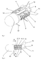
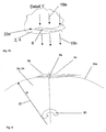
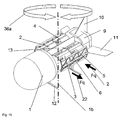
- the aircraft according to Fig. 1 to Fig. 6 consists of a hull 1 with a longitudinal axis 1a and four parallel to this longitudinal axis 1a preferably above the center of gravity arranged buoyancy bodies 2, 3, 4 and 5, which are protected by a side guard 6 against collision with a fixed obstacle.
- a tailplane 11 and a rudder 10 preferably also the drive unit z.
- turbofan engines that give the aircraft a high cruising speed or support the start and landing process with appropriate swivel design.
- Runners or similar legs 12 support the aircraft on the ground.
- longitudinal struts 13, 14, which may have a streamlined cross-sectional shape or a weight-optimized truss structure
- the rear area of the aircraft is connected to the front area, further with the longitudinal struts and the side guard is a stable construction for a storage (not shown here) of the buoyancy bodies 2, 3, 4, 5 provided in the central region.
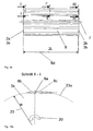
- Fig. 2 the length ratios can be seen, after which the length of the rotating buoyancy bodies 2, 3, 4, 5 corresponds to about 50% of the total length, preferably 30 to 70%, of the aircraft.
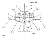
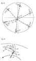
- Fig. 3 are the opposite direction about the axes of rotation 7a, 7b rotating buoyancy body 2, 3, 4, 5 with the directions of rotation 20a, 20b and required for generating the buoyancy rotor blades 8 can be seen.
- the additional drive units not shown here, are provided and to reduce the air resistance, the buoyancy bodies 2, 3, 4, 5, which can not produce the required buoyancy at a high cruising speed, by means of suitable Cover skirts streamlined in the aircraft covered. According to Fig.
- these trim skirts may be formed as compact surfaces 40a, 40b (such as in FIG Fig. 4 in the open state, for an optimal effect of the buoyancy bodies, shown), or as a system of fins 40a ', 40b', 41a ', 41b', which can be made either to a closed casing or for an unobstructed air passage.
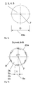
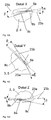
- a buoyancy body 2, 3, 4, 5 consists essentially of a rotation axis 7, two end disks 2a - 2b, 3a - 3b, 4a - 4b, 5a - 5b with the diameter D 23b and a certain number (preferably 4 to 10) of rotor blades 8, which are arranged movably around a pivot axis 8a in the two end disks (eg, 2a-2b), and in the case of one complete revolution, describe a circular path 23a with the radius R 23.
- the depth of the rotor blade t 8e is dependent on the order of magnitude of the overall construction and is about 30 to 50% of the circular path radius R 23, the length L 8d of the rotor blade 8 is preferably about 25 to 35% of the total length of the aircraft.
- the buoyancy body rotates at nominal speed (preferably about 750 to 3000 rpm) about the axis of rotation 7, and during one full revolution, the rotor blades 8 in each instantaneous position become individual with respect to the tangent 23b of the circular path 23a of radius R 23 employed, so that in the upper and lower extreme position maximum buoyancy forces can be generated and act in the two vertical extreme positions exclusively flow resistance forces on the rotor blade.
- the preferred arrangement of the direction of rotation 20 of the buoyancy bodies in the aircraft is in opposite directions.
- Fig. 8 the flow conditions are shown in more detail, wherein due to the rotor blade geometry, the wing theory is relevant, according to which each below the salaried rotor blade at a defined relative speed, a pressure increase and above a negative pressure is generated.
- the corresponding Force components acting on a rotor blade result from these two pressure components.
- ambient air is preferably sucked from above 18a, pressed into the rotating buoyancy body 18b, sucked down 19a and 19b pressed out.
- An optimal variant is in the Fig. 9 .
- the rotor blade 8 consists of at least three elements, namely a stable pivot axis 8a, a movable rotor blade nose 8b and a movable rotor blade tip 8c.
- the rotor blade nose 8b are pivotable by the angle ⁇ 21a, preferably by +/- 3 ° -10 ° relative to the tangent of the circular path 23a, and the rotor blade tip 8c by the angle ⁇ 21b, preferably by +/- 3 ° to 10 ° pivotable relative to the tangent of the circular path 23a.
- the rotor blade tip and the rotor blade nose are pivotable by> 90 °, preferably approx. 105 °.
- Fig. 9a is a vertical force component Fa 22 in the direction of rotation axis 7 of the buoyant body generated when at rated speed in the upper extreme position, the rotor blade nose 8b with the angle ⁇ ⁇ 0 ° and the rotor blade tip with the angle ⁇ > 0 °, each with respect to the tangent direction 23b of the orbit 23a, and vice versa according to Fig.
- FIG. 9b is a vertical force component Fa 22 opposite direction of rotation axis 7 of the buoyant body generated when at rated speed in the upper extreme position, the rotor blade nose 8b with the angle ⁇ > 0 ° and the rotor blade tip with the angle ⁇ ⁇ 0 °, each with respect to the tangent direction 23b of the orbit 23a, to be hired.
- the two counter-driven buoyancy bodies are shown in detail with the optimum for the production of a maximum buoyancy force at rated speed employment of the rotor blades in the different positions.
- Fig. 10a shows the angular relationships of the rotor blade nose and rotor blade tip when entering the upper orbit after leaving the neutral vertical position
- Fig. 10a shows the angular relationships of the rotor blade nose and rotor blade tip when entering the upper orbit after leaving the neutral vertical position
- FIG. 10b shows the angular relationships of the rotor blade nose and rotor blade tip in the upper extreme position of the orbit
- Fig. 10c shows the angular relationships of the rotor blade nose and rotor blade tip in the upper orbit before entering the neutral vertical position
- Fig. 10d shows the angular relationships of the rotor blade nose and rotor blade tip in the lower extreme position of the orbit.
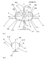
- a stable equilibrium position in Fig. 11 to Fig. 12b in the air is given by the fact that each buoyancy body 2, 3, 4, 5 can generate individual buoyancy forces A 1 to A 4 35 a, 35 b, 35 c and 35 d and thus a state of equilibrium to the total mass center of gravity S 32 of the total mass m 33 and to Main mass center of mass 32a of the submass from the cockpit m 1 33a, with the partial center of gravity distance s 1 34a, and 32b of the submass from the rear of the aircraft m 2 33b, with the partial center of gravity distance s 2 34b, and the lateral center of gravity distance s 3 34c of the total mass center of gravity S 32 of Total mass m 33 can be made to any situation. This can be reacted to changing equilibrium situations at any time.
- a transition from a floating state to a slow forward movement or backward movement is possible in that the aircraft has a tilt attitude ( Fig. 13 ), and from the resultant buoyant force 35a, 35b, a force component 35a ', 35b' can be derived which enables forward and reverse acceleration, respectively, while the vertical force component 35a ", 35b" continues to vertically balance the aircraft.
- FIG. 14 is a transverse motion with the velocity v x 36, which is achieved in that according to Fig. 14a the rotor blades are brought in the position of the vertical extreme position in a corresponding inclination position 21, so that air from one direction sucked 18a and almost across the aircraft squeezed out 19b; here too the wing theory has to be applied.
- Fig. 14b the rotor blade position is shown in a neutral position while according to the rotor blade position after Fig.
- a force component Fq 22 would be exerted on the aircraft away from the axis of rotation and would have a movement with the velocity v x 36 from right to left result and gem.
- a force component Fq 22 would be exerted on the aircraft in the opposite direction, in the direction of the axis of rotation and would result in a movement with the velocity v x 36 from left to right.
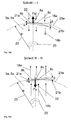
- Fig. 16 The same effects and maneuvers as described above can be achieved even if instead of four four buoyancy bodies 2, 3 arranged in pairs in opposite directions are used, but which are executed with a double length 2L 8d ( Fig. 16 ).
- the rotor blades are elastically deformable about the pivot axis 8a.
- the rotor blade nose 8b and the rotor blade tip 8c can be displaced in parallel at both ends or differently.
- Fig. 16a is a neutral position of the rotor blade (section II - II of Fig. 16 ), as in accordance with an opposite direction displacement of the two ends of the rotor blade.
- Fig. 16b (Section I - I of Fig. 16 ) and Fig.
- FIG. 17 shows the corresponding angle of attack ⁇ 21 of the rotor blades and the relative air flow 41 and the direction of rotation 20 of the buoyancy bodies, when the aircraft falls with the sinking speed 40 in free fall in the vertical direction downwards.
- FIG. 18 Another variant of an aircraft with two oppositely rotating buoyancy bodies 2, 3 is in Fig. 18 shown, where Fig. 18a a side view and Fig. 18b shows a front view.
- the two oppositely rotating buoyancy bodies are arranged along the central axis of the aircraft along a common axis of rotation behind one another.
- Fig. 18c shows a section I - I of Fig. 18a in which the bearing of the axis of rotation of the buoyancy bodies 2, 3 and the side protection panel are shown.
- Fig. 18d shows the section II - II of Fig. 18a and Fig. 18e the section III - III of Fig. 18a from which the arrangement and direction of rotation of the two successive buoyancy bodies are visible, in the illustration for a usual limbo or climb.
- Fig. 18f shows the section II - II of Fig. 18a
- Fig. 18g shows the section III - III of Fig. 18a in the position of the rotor blades to achieve the autorotation in free descent to z. B. failure of a drive unit.
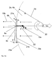
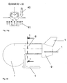
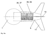
- Fig. 19 shows a further embodiment of an aircraft, suitable for vertical take-off and landing, but executed with buoyancy bodies 36, 37, 38, 39, which are designed as cross-flow rotors.
- Fig. 19a shows the top view of such an aircraft and
- Fig. 19b a representation according to section I - I of Fig. 19 ,
- so-called cross-flow rotors are in use, which are provided with outer Strömungsleit Huaweien 6, which are arranged correspondingly adjustable and in turn can achieve a virtually unlimited maneuverability (forward movement, backward movement, transverse movement, rotational movement about the vertical axis).
- buoyant bodies 36, 37, 38, 39 designed as cross-flow rotors, each consist of two round end disks, which carry a multiplicity of rotor blades 36a, 37a and rotate about an axis of rotation.
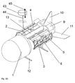
- a designated as a reconnaissance unit 43 unit radar, optical sensor, (7) may be provided, which can be spent when needed in the floating state of the aircraft, by means of a flexible connection 44 vertically up and then retracted.
- a submergence enemy radar beams behind protective coverings in the field or in building fills is to be achieved, and for detecting the military situation z.
- B. behind a protective terrain formation instead of a short-term dangerous "emergence" only the reconnaissance device 43 shot vertically into the air, recorded the military situation and then the reconnaissance device with the flexible connection is again securely inserted into the fuselage of the aircraft.
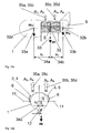
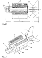
- the aircraft of the Fig. 21 consists of a hull 1 with a longitudinal axis 1a and two arranged above this longitudinal axis 1a cross-flow rotors 2 and 3.
- a tailplane 11 and a rudder 10 is provided in the rear of the hull.
- Runners 46 support the aircraft on the ground.
- two turbofan engines 47 are provided in the area of the tail units 4, 5 in order to produce the necessary propulsion.
- Fig. 25 is the structure of the aircraft in greater detail shown in section.
- the rotors 2, 3 have a plurality of blades 8 arranged along the circumference.
- the rotors 2, 3 are each covered by a first guide surface 49 and a second guide surface 50.
- the first guide surface 49 is formed as part of the outer surface of the fuselage 1, while the second guide surface 50 is formed in each case as a flow baffle.
- the upper open area of the rotors 2, 3 thus serves as the air inlet opening 54, and the lower open area as the air outlet opening 55.
- the impulse of the downwardly expelled air quantities results in a total lifting force on the aircraft, which is represented by the arrow 56 and the with sufficient design sufficient to lift the aircraft from the ground.
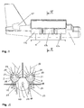
- 3 adjustable guide vanes 17 are provided which in the embodiments of the Fig. 24 consist of several segments 17a, 17b, 17c, which are independently pivotable about an axis parallel to the longitudinal axis of the aircraft. As a result, rotation of the aircraft about a vertical axis 1b can also be effected by the guide vanes 17. It is shown that the guide vanes 17 arranged below the air discharge openings 55 can be modified correspondingly to the direction of the air jets in the direction of the arrows 53. In the in Fig. 6 shown position is generated by pivoting the movable vanes 17, a force component to port, which is indicated by the arrow 56. Within the cross-flow rotors guide vanes 58 may be provided for improved air flow guidance. The vanes 58 may be movable, which improves maneuverability with high efficiency.
- the drive of the cross-flow rotors 2, 3 can be done in principle by piston engines, but is preferably carried out on gas turbines, which is not shown in the drawings.
- Fig. 26 It can be seen that the individual rotor blades 8 are arranged pivotably about a pivot point 61 via a pull rod 60.
- the tie rods 60 are mounted in a common star point 62, which arbitrarily opposite to the Axis 63 can be moved. This allows a total flow to be set in any direction.
- the rotor blades 8 are guided by pins 64 in scenes 65 to ensure the appropriate stability.
- an end region 66 of the rotor blade 8 is separately adjustable.
- a connected to the end portion 66 lever 67 has a pin 68 which is guided in a second link 69, so that the rotor blade 8 assumes an asymmetric airfoil profile, which improves the flow rate and efficiency.
- the present invention describes an aircraft which has the possibility of a vertical take-off and a vertical landing, allows an almost unlimited maneuverability in limbo, offers a high cruising speed with simultaneous fuel economy, allowing the pilot to safely leave the aircraft when needed and a flexibly arranged reconnaissance device accommodates above the aircraft.
Landscapes
- Engineering & Computer Science (AREA)
- Aviation & Aerospace Engineering (AREA)
- Toys (AREA)
- Radio Relay Systems (AREA)
- Details Of Aerials (AREA)
- Fluid-Pressure Circuits (AREA)
- Other Liquid Machine Or Engine Such As Wave Power Use (AREA)
- Containers And Packaging Bodies Having A Special Means To Remove Contents (AREA)
- Refuse Collection And Transfer (AREA)
- Percussion Or Vibration Massage (AREA)
- Application Of Or Painting With Fluid Materials (AREA)
- Transmission Devices (AREA)
Abstract
Description
Die vorliegende Erfindung betrifft ein Fluggerät gemäß dem Oberbegriff von Patentanspruch 1.The present invention relates to an aircraft according to the preamble of
Insbesondere ist ein solches Fluggerät mit einem System spezieller Auftriebskörper versehen, die als Rotoren ausgebildet sind, mit einer Drehachse die im Wesentlichen parallel zur Längsachse des Fluggerätes angeordnet ist. Dabei ist jeder Rotor mit einer bestimmten Anzahl tragflügelähnlicher Rotorblätter versehen, die im wesentlichen an zwei scheibenähnlichen Endkörpern derart angeordnet sind, dass während einer vollen Umdrehung des Auftriebskörpers (Rotors) die Mittelachse des Rotorblattes eine Kreisbewegung mit dem Abstand von der Drehachse als Radius ausführt, und das Rotorblatt vorzugsweise während einer vollen Umdrehung individuell in seiner Lage verändert werden kann. Damit kann in jeder augenblicklichen Position des Rotorblattes eine definierte Krafteinwirkung (z. B. Auftriebskraft, Querkraft) auf das Fluggerät erzeugt werden.In particular, such an aircraft is provided with a system of special buoyancy bodies, which are designed as rotors, with an axis of rotation which is arranged substantially parallel to the longitudinal axis of the aircraft. In this case, each rotor is provided with a certain number of wing-like rotor blades, which are arranged substantially on two disk-like end bodies such that during a full revolution of the buoyancy body (rotor), the central axis of the rotor blade performs a circular motion with the distance from the axis of rotation as radius, and the rotor blade can preferably be changed individually in its position during a full revolution. Thus, a defined force (eg buoyancy, lateral force) can be generated on the aircraft in each instantaneous position of the rotor blade.
Es sind vielfache Anstrengungen unternommen worden, die Vorteile eines Flugzeugs mit denen eines Hubschraubers zu vereinen. Von besonderem Interesse ist dabei die Eigenschaft von Hubschraubern, senkrecht starten und landen zu können, oder auch bei Bedarf in der Luft stillstehen zu können, um beispielsweise Personen zu bergen, bzw. um spezielle Transport- und Montageflugmanöver oder ähnliche Aufgaben zu erfüllen. Nachteilig bei bestehenden Hubschraubern sind, der hohe technische Aufwand, insbesondere im Bereich der Rotorsteuerung, sowie das enorme Absturzrisiko bereits bei geringfügigster Berührung der rotierenden Rotorflügel mit einem Hindernis wie z. B Baumwipfel oder Felswände. Gerade Einsatzbedingungen, wie Alpinbergungen, sind äußerst kritisch, da einerseits eine Position möglichst nahe an z. B. einer Felswand erforderlich wäre, andererseits die geringste Kollision bereits fatale Auswirkungen zur Folge hat; somit kann nur unter Einhaltung entsprechend großer Sicherheitsabstände gearbeitet werden. Ein weiterer Nachteil ist der hohe Treibstoffverbrauch von Hubschraubern, der auch im Reiseflug gegeben ist. Um diese Nachteile zu vermeiden, sind so VTOL- oder STOL-Flugzeuge entwickelt worden, die vom Aufbau her grundsätzlich Flugzeugen ähneln, jedoch durch verschiedene technische Maßnahmen mit der Fähigkeit ausgestattet sind, senkrecht starten und landen zu können, oder zumindest mit extrem kurzen Start- und Landebahnen auskommen.Much effort has been made to combine the advantages of an aircraft with those of a helicopter. Of particular interest is the ability of helicopters to start and land vertically, or to be able to stand in the air when needed, for example, to salvage people, or to perform special transport and assembly maneuvers or similar tasks. A disadvantage of existing helicopters are the high technical complexity, especially in the field of rotor control, and the enormous risk of falling already at the slightest touch the rotating rotor blades with an obstacle such. B treetops or rock walls. Straight conditions of use, such as alpine climbs, are extremely critical, since on the one hand a position as close as possible to z. B. a rock wall would be required, on the other hand, the slightest collision has already fatal consequences; Thus, you can only work in compliance with correspondingly large safety distances. Another disadvantage is the high fuel consumption of helicopters, which is also in cruising flight. In order to avoid these disadvantages, VTOL or STOL aircraft have been developed, which are fundamentally similar in design to aircraft, but are equipped by various technical measures with the ability to start and land vertically, or at least with extremely short takeoff. and runways get along.
Eine solche Lösung ist beispielsweise in der
Nachteilig bei dieser bekannten Lösung ist zum einen, dass die auf die Auftriebserzeugung optimierten Tragflächen einen hohen Luftwiderstand aufweisen, so dass der Treibstoffverbrauch insbesondere bei höheren Fluggeschwindigkeiten übermäßig groß ist und dass das Fluggerät insgesamt eine relativ große Spannweite aufweist. Es benötigt daher viel Platz und ist auch unter beengten Verhältnissen nicht oder nur schlecht einsetzbar.A disadvantage of this known solution, on the one hand, that the optimized on the lift generation wings have a high air resistance, so that fuel consumption is excessively high, especially at higher airspeeds, and that the aircraft as a whole has a relatively large span. It therefore takes up a lot of space and is not or only poorly usable in cramped conditions.
Weitere Fluggeräte sind in der
Ein weiteres Fluggerät, das Auftrieb unter Verwendung von abgewandelten Querstromventilatoren erzeugt, ist in der
Ein weiteres Fluggerät mit einem Querstromrotor als Antriebselement ist aus der
Ein weiteres bekanntes Fluggerät mit der Möglichkeit des Senkrechtstarts ist in der
Dem Stand der Technik nahe liegend ist auch jenes Antriebskonzept für Wasserfahrzeuge, welches als Voith - Schneider Antrieb bekannt ist. Dieses seit ca. 75 Jahren bekannte Antriebssystem unterscheidet sich im Wesentlichen dadurch, dass die Schwenkbewegung der einzelnen Schaufeln, während einer vollen Umdrehung des Drehkranzes, in einem festen kinematischen Verhältnis zueinander abläuft. Damit ist eine Vorschubkraft immer nur in eine einzige Richtung möglich. Im Unterschied dazu ist bei dem hier vorgestellten erfinderischen rotierenden Auftriebskörper, unabhängig von einer ersten Kraftkomponente, z. B. gleich bleibende vertikale Auftriebskomponente, eine zweite Kraftkomponente in Querrichtung erzeugbar.The prior art also suggests that drive concept for watercraft, which is known as Voith - Schneider drive. This drive system known for about 75 years differs essentially in that the pivoting movement of the individual blades during a full rotation of the turntable, runs in a fixed kinematic relationship to each other. Thus, a feed force is possible only in a single direction. In contrast, in the presented here inventive rotating buoyancy body, regardless of a first force component, z. B. constant vertical buoyancy component, a second force component in the transverse direction can be generated.
Ferner zeigen die
Die gegenständliche Erfindung bezieht sich auf weitere Ausführungsvarianten von VTOL-Fluggeräten, die mit rotierenden Auftriebskörpern ausgerüstet sind, deren Drehachse im Wesentlichen parallel zur Längsachse des Fluggerätes angeordnet ist.The subject invention relates to further variants of VTOL aircraft, which are equipped with rotating buoyancy bodies whose Rotary axis is arranged substantially parallel to the longitudinal axis of the aircraft.
Aufgabe der vorliegenden Erfindung ist es, ein Fluggerät zu schaffen, das einen senkrechten Start und eine senkrechte Landung ermöglicht, das in der Luft einen Schwebezustand einnehmen kann, mit einer Beweglichkeit, die eine langsame Vorwärts-, Rückwärts-, parallele Seitwärtsbewegung nach Backbord oder Steuerbord sowie eine Drehbewegung um die Vertikalachse in bzw. gegen den Uhrzeigersinn ausführen kann, und das gleichzeitig für eine hohe Reisefluggeschwindigkeit geeignet ist. Durch die gewählte Ausbildung der äußeren geometrischen Form des Fluggerätes ist der Übergang von einem Schwebezustand in eine Vorwärtsbewegung mit hoher Reisefluggeschwindigkeit zu gewährleisten. Insbesondere soll dabei eine hohe Treibstoffökonomie erreicht werden, bei vergleichsweise geringem, technischem Aufwand. Ein weiterer Anspruch betrifft die Erfüllung der höchsten sicherheitstechnischen Standards, die dem Fluggerät selbst bei einem Totalausfall der Antriebsmotore eine sichere Landung ermöglichen. Weiters sollen die rotierenden Auftriebskörper mit einer Verkleidung derart geschützt werden, dass das Fluggerät auch sehr nahe an Hindernisse (z. B. Felswand, Hochhauswand) heran manövriert werden kann und dass selbst bei Berührung des Fluggerätes mit einem Hindernis, bedingt durch die gegen Kollision geschützten rotierenden Elemente des Auftriebskörpers, ein Absturz sicher verhindert werden kann. Ein für den Piloten sicheres und kollisionsfreies Verlassen des Fluggerätes mittels Schleudersitz ist ebenfalls möglich, und stellt einen weiteren Anspruch dar. Eine besondere Aufgabe der Erfindung ist es, einen hohen Wirkungsgrad bei der Erzeugung des erforderlichen Auftriebs zu erreichen.Object of the present invention is to provide an aircraft that allows a vertical take-off and a vertical landing, which can take a hover in the air, with a mobility, the slow forward, backward, parallel sideways movement to port or starboard and a rotational movement about the vertical axis clockwise or counterclockwise, and at the same time is suitable for a high cruising speed. The selected design of the outer geometric shape of the aircraft, the transition from a limp state in a forward movement with high cruise speed is to ensure. In particular, a high fuel economy is to be achieved, with comparatively little technical effort. Another claim relates to the fulfillment of the highest safety standards that allow the aircraft to land safely even in the event of a total failure of the propulsion engines. Furthermore, the rotating buoyancy bodies are to be protected with a fairing such that the aircraft can also be maneuvered very close to obstacles (eg rock wall, high-rise wall) and even with contact with the aircraft with an obstacle, due to the protected against collision rotating elements of the buoyant body, a fall can be safely prevented. A safe for the pilot and collision-free leaving the aircraft by means of ejection seat is also possible, and is another claim. A particular object of the invention is to achieve a high efficiency in the generation of the required buoyancy.
Erfindungsgemäß werden diese Aufgaben durch die Merkmale von Patentanspruch 1 gelöst. Wichtig ist, dass die Auftriebskörper durch mindestens ein Antriebsaggregat angetrieben sind und jeweils eine Zylinderachse aufweisen, die im Wesentlichen parallel zu einer Längsachse des Fluggerätes ist. Dabei ist jeder Rotor mit einer bestimmten Anzahl tragflügelähnlicher Rotorflügel versehen, die im wesentlichen an zwei scheibenähnlichen Endkörpern derart angeordnet sind, dass während einer vollen Umdrehung des Auftriebskörpers (Rotors) die Mittelachse des Rotorblattes eine Kreisbewegung mit dem Abstand von der Drehachse als Radius ausführt, und das Rotorblatt vorzugsweise während einer vollen Umdrehung individuell in seiner Lage verändert werden kann. Damit kann in jeder augenblicklichen Position des Rotorblattes eine definierte Krafteinwirkung (z. B. Auftriebskraft, Querkraft) auf das Fluggerät erzeugt werden. Diese Veränderung der Lage erfolgt, indem der hintere Abschnitt des Rotorblattes unabhängig vom vorderen Abschnitt schwenkbar ist, um so eine jeweils optimale Tragflügelform zu erreichen.According to the invention, these objects are achieved by the features of
Durch geeignete Wahl der Anordnung der Auftriebskörper im Fluggerät ist zudem der Raum oberhalb der Pilotenkanzel freigehalten, sodass dem Piloten ein sicheres und kollisionsfreies Verlassen des Fluggerätes mittels Schleudersitz möglich ist (dies ist z. B. bei einem Hubschrauber nicht möglich).By a suitable choice of the arrangement of the buoyancy bodies in the aircraft also the space above the cockpit is kept free, so that the pilot a safe and collision-free leaving the aircraft by means of ejector seat is possible (this is not possible, for example, in a helicopter).
Für den militärischen Einsatzbereich bietet diese Anordnung der Auftriebskörper eine weitere Möglichkeit und zwar können für Aufklärungszwecke Radar- bzw. andere optische Geräte auch oberhalb des Fluggerätes angeordnet werden. Mit diesem Fluggerät ist es nicht notwendig eine schützende Geländeformation zu verlassen, ohne zuvor mit einem flexibel mit dem Fluggerät verbundenen Aufklärungsgerät, welches z. B. vertikal oberhalb des im Schwebezustand verharrenden Fluggerätes in die Höhe verbracht und anschließend wieder eingeholt werden kann, das Geschehen hinter der Geländeformation erfasst und beurteilt zu haben.For military use, this arrangement of the buoyancy body offers a further possibility and although radar or other optical devices can also be arranged above the aircraft for reconnaissance purposes. With this aircraft, it is not necessary to leave a protective terrain formation, without previously with a flexibly connected to the aircraft reconnaissance device, which z. B. vertically above the suspended in the airborne aircraft in the air and then can be obtained again, recorded the events behind the terrain formation and judged.
Die erfindungsgemäße Lösung erlaubt ein Manövrieren des Fluggeräts auch bei niedrigen Geschwindigkeiten oder im Schwebflug, ohne die Drehzahl des Antriebsaggregats verändern zu müssen, da Richtung und Stärke der Auftriebskräfte durch die Steuerung der Rotorblätter in weiten Grenzen variierbar sind. Dadurch wird eine extrem große Wendigkeit erreicht.The inventive solution allows a maneuvering of the aircraft even at low speeds or in a hover flight without having to change the speed of the drive unit, since the direction and strength of the buoyancy forces by the control of the rotor blades can be varied within wide limits. This achieves extremely high maneuverability.
Durch die Anordnung der Auftriebskörper parallel zum Rumpf können mehrere Vorteile gleichzeitig erreicht werden. Zum einen können die Auftriebskörper einen relativ großen Durchmesser aufweisen, ohne die Querschnittsfläche in Fortbewegungsrichtung allzu sehr zu erhöhen, wodurch auch im schnellen Reiseflug ein geringer Treibstoffbedarf gegeben ist. Zum anderen ist das erfindungsgemäße Fluggerät äußerst kompakt aufgebaut und benötigt somit nicht nur wenig Platz in einem Hangar oder dergleichen, sondern ist auch extrem wendig. Dies ermöglicht beispielsweise die Landung auf Waldlichtungen oder im inner städtischen Bereich zwischen Bauwerken, wo die Landung eines Hubschraubers aufgrund des vorgegebenen Rotordurchmessers nicht mehr möglich wäre. Überdies sind die als Rotor ausgebildeten Auftriebskörper besonders robust im Aufbau und umfassen im Allgemeinen außer den Rotorblättern selbst keine weiteren beweglichen Teile, so dass der technische Aufwand vertretbar ist. Durch die Anbringung der Auftriebskörper im unmittelbaren Nahbereich des Rumpfes ist die mechanische Beanspruchung der Rotoraufhängungen sehr gering, so dass eine entsprechende Leichtbauweise möglich ist, die wiederum zur Treibstoffersparnis beiträgt.By arranging the buoyancy bodies parallel to the hull several advantages can be achieved simultaneously. On the one hand, the buoyancy bodies can have a relatively large diameter without too much increase in the cross-sectional area in the direction of travel, as a result of which a low fuel requirement is given even in fast cruising flight. On the other hand, the aircraft according to the invention is extremely compact and thus not only requires little space in a hangar or the like, but is also extremely manoeuvrable. This allows, for example, the landing on forest clearings or in the inner urban area between buildings where the landing of a helicopter due to the given rotor diameter would no longer be possible. Moreover, the buoyancy bodies designed as a rotor are particularly robust in construction and generally do not include any other moving parts except for the rotor blades themselves, so that the technical outlay is justifiable. By attaching the buoyancy bodies in the immediate vicinity of the fuselage, the mechanical stress of the rotor suspensions is very low, so that a corresponding lightweight construction is possible, which in turn contributes to fuel economy.
Eine besonders raumökonomische Anordnung der einzelnen Bauteile ist gegeben, wenn die Auftriebskörper im oberen Bereich des Rumpfes angeordnet sind. Zusätzlich wird dadurch eine besonders aerodynamisch günstige Ausführung erreicht, da der Ansaugbereich völlig frei und unbehindert durch sonstige Bauteile des Fluggerätes angeströmt werden kann.A particularly space-economical arrangement of the individual components is given when the buoyancy bodies are arranged in the upper region of the fuselage. In addition, this achieves a particularly aerodynamically favorable design, since the intake can be flowed freely and unhindered by other components of the aircraft.
Eine weitere besonders begünstigte Ausführungsvariante der Erfindung sieht vor, dass die Auftriebskörper durch Gasturbinen gegenläufig angetrieben sind. Ähnlich wie bei Hubschraubern ist auch hier bei Einsatz von Gasturbinen ein besonders günstiges Verhältnis von Leistung zu Eigengewicht gegeben. Ein zusätzlicher Vorteil gegenüber Hubschraubern besteht bei der vorliegenden Erfindung darin, dass die Drehzahlen der rotierenden Auftriebskörper wesentlich höher liegen als die von üblichen Hubschrauberrotoren, so dass sich der bauliche Aufwand für Getriebe wesentlich verringert. Je nach Baugröße, Einsatzzweck und Sicherheitsvorschriften können die beiden Rotoren von einer gemeinsamen Gasturbine angetrieben werden, oder es kann jedem Auftriebskörper eine eigene Gasturbine zugeordnet werden.Another particularly favorable embodiment of the invention provides that the buoyancy bodies are driven in opposite directions by gas turbines. Similar to helicopters, a particularly favorable ratio of power to dead weight is given here with the use of gas turbines. An additional advantage over helicopters is in the present invention is that the rotational speeds of the rotating buoyancy bodies are much higher than that of conventional helicopter rotors, so that the construction cost of transmission significantly reduced. Depending on the size, purpose and safety regulations, the two rotors can be driven by a common gas turbine, or it can be assigned to each buoyancy body own gas turbine.
Der Wirkungsgrad der Auftriebskörper kann insbesondere dadurch weiter verbessert werden, dass die im Rotor beweglich angeordneten Rotorblätter aus mindestens einer feststehenden Achse und zwei unabhängig voneinander beweglichen Rotorblattsegmenten bestehen, damit die Rotorblattgeometrie in jedem Augenblick in jeder aktuellen Position optimal an die jeweilige Situation angepasst werden kann; damit können sowohl die Auftriebskräfte und Seitenkräfte optimiert und die Widerstandskräfte minimiert werden.The efficiency of the buoyancy bodies can be further improved, in particular, by virtue of the fact that the rotor blades movably arranged in the rotor consist of at least one stationary axle and two independently movable rotor blade segments, so that the rotor blade geometry can be optimally adapted to the respective situation at every instant in every current position; thus both the buoyancy forces and lateral forces can be optimized and the resistance forces can be minimized.
Besonders hohe Reisegeschwindigkeiten können dadurch erreicht werden, dass zusätzliche Triebwerke zur Erzeugung eines Schubs für den Vortrieb des Fluggerätes vorgesehen sind. An sich ist es möglich und grundsätzlich für geringere Reisegeschwindigkeiten auch ausreichend, dass der Vortrieb durch die verstellbaren Rotorflügel der Auftriebskörper erzeugt wird, in dem das Fluggerät in eine nach vorne abgesenkte Lage gebracht wird und aus der resultierenden Auftriebskraft eine Vorschubkraft abgeleitet wird. Die Reisegeschwindigkeit ist jedoch in diesem Fall begrenzt, so dass für höhere Reisegeschwindigkeiten in vorteilhafter Weise zusätzliche Triebwerke eingesetzt werden. Diese können beispielsweise als Mantelstromtriebwerke ausgebildet werden. Der Start- und Landevorgang kann dadurch unterstützt werden, dass die zusätzlichen Triebwerke schwenkbar angeordnet sind. Einerseits kann dadurch die Auftriebskraft erhöht werden, wenn der Triebwerksstrahl senkrecht nach unten gerichtet ist, und andererseits kann durch entsprechende Steuerung des Schwenkwinkels die Manövrierbarkeit zusätzlich erhöht werden.Particularly high cruising speeds can be achieved by providing additional thrusters for generating a thrust for the propulsion of the aircraft. In itself, it is possible and generally sufficient for lower travel speeds that the propulsion is generated by the adjustable rotor blades of the buoyancy bodies, in which the aircraft is brought into a lowered forward position and from the resulting buoyancy force a feed force is derived. However, the cruising speed is limited in this case, so that additional engines are advantageously used for higher cruising speeds. These can be formed, for example, as turbofan engines. The takeoff and landing can be supported by the fact that the additional engines are arranged pivotally. On the one hand, the buoyancy force can thereby be increased if the engine jet is directed vertically downwards, and on the other hand, the maneuverability can be additionally increased by appropriate control of the swivel angle.
Der Treibstoffverbrauch beim Senkrechtstart bzw. bei der Landung und beim Schwebeflug wird maßgeblich von der umgesetzten Luftmenge beeinflusst. Es ist daher insbesondere günstig, wenn sich die Auftriebskörper über mindestens 40%, vorzugsweise über mindestens 70% der Länge des Rumpfes erstrecken.The fuel consumption during vertical take-off or landing and during hovering is significantly influenced by the amount of air converted. It is therefore particularly favorable if the buoyancy bodies extend over at least 40%, preferably over at least 70%, of the length of the fuselage.
Auf diese Weise ist es möglich, bei vorgegebener Querschnittsfläche eine größtmögliche Auftriebsleistung der Auftriebskörper zu erzielen.In this way, it is possible to achieve the greatest possible buoyancy of the buoyancy body for a given cross-sectional area.
Die Manövrierfähigkeit, insbesondere im Schwebeflug und beim Start bzw. bei der Landung, kann dadurch verbessert werden, dass im Bereich der Luftauslassöffnungen verstellbare Leitschaufeln vorgesehen sind. Bei niedrigen Fluggeschwindigkeiten ist die Möglichkeit der Steuerung durch das Leitwerk stark eingeschränkt, so dass sich eine ausreichende Manövrierbarkeit durch die individuelle Verstellbarkeit der Rotorblätter ergibt. Um eine Rotation des Fluggerätes auch um eine vertikale Achse zu ermöglichen, ist es in diesem Zusammenhang besonders bevorzugt, wenn die verstellbaren Rotorblätter in zwei paarweise gegenläufigen Auftriebskörpern angeordnet sind und aus jeweils zwei Segmenten bestehen, die unabhängig voneinander betätig bar sind. Weitere verstellbare Leitschaufeln, die um eine Querachse des Fluggerätes schwenkbar sind, ermöglichen eine Vorwärts- und Rückwärtsbewegung im Schwebezustand, die besonders fein steuerbar ist.The maneuverability, in particular during hovering and take-off or landing, can be improved by providing adjustable guide vanes in the area of the air outlet openings. At low airspeeds, the possibility of control by the tail is severely limited, so that there is sufficient maneuverability through the individual adjustability of the rotor blades. In order to enable a rotation of the aircraft about a vertical axis, it is particularly preferred in this context, when the adjustable rotor blades are arranged in two pairs opposing buoyancy bodies and each consist of two segments that are independently actu bar. Further adjustable guide vanes, which are pivotable about a transverse axis of the aircraft, allow a forward and backward movement in the floating state, which is particularly finely controlled.
Weiters ist es besonders bevorzugt, wenn die Auftriebskörper mit einer äußeren Verkleidung als mechanischen Schutz der Rotorblätter gegen eine Kollision mit einem festen Hindernis ausgebildet sind. Dies bedeutet, dass die Verkleidung nicht nur zur Aufnahme der Lagerung der Rotorwelle, sondern auch in mechanisch entsprechend robuster Weise ausgebildet ist, um die Auftriebskörper gegenüber einer Beschädigung zu schützen, wenn das Fluggerät mir geringer Relativgeschwindigkeit eine Kollision mit einem Hindernis erleidet.Furthermore, it is particularly preferred if the buoyancy bodies are designed with an outer cladding as mechanical protection of the rotor blades against a collision with a fixed obstacle. This means that the cladding is designed not only for receiving the bearing of the rotor shaft, but also in mechanically correspondingly robust manner, in order to protect the buoyancy bodies against damage when the aircraft encounters a low relative speed collision with an obstacle.
In der Folge wird die vorliegend Erfindung anhand der in den Figuren dargestellten Ausführungsbeispiele näher erläutert. Dabei zeigen
- Fig. 1
- eine schematische Ansicht eine ersten Ausführungsvariante eines erfindungsgemäßen Fluggerätes in axonometrischer Darstellung;
- Fig. 2
- eine Seitenansicht des Fluggerätes von
Fig. 1 ; - Fig. 3
- einen Schnitt des Fluggerätes von
Fig. 1 entlang der Linie A - A inFig. 2 ; - Fig. 4
- einen Schnitt des Fluggerätes von
Fig. 1 entlang der Linie A - A inFig. 2 mit der Darstellung einer geöffneten bzw. geschlossenen Verkleidung der Auftriebskörper, wie sie für eine hohe Reisegeschwindigkeit vorgesehen sind; - Fig. 5
- eine Ansicht des Fluggerätes von
Fig. 1 von vorne; - Fig. 6
- eine Ansicht des Fluggerätes von
Fig. 1 von oben; - Fig. 7
- und
Fig. 7b schematisch einen Auftriebskörper des Fluggerätes vonFig. 1 ; - Fig. 8,
-
Fig. 8a undFig. 8b die Anordnung, Drehrichtung und Wirkungsweise des Auftriebskörpers des Fluggerätes vonFig. 1 ; - Fig. 9,
-
Fig. 9a und Fig. 9b ein Rotorblatt mit zwei beweglichen Segmenten im Querschnitt in der Stellung Auftriebskräfte neutral, maximaler Auftrieb und negativer Auftrieb des Fluggerätes vonFig. 1 ; - Fig. 10,
-
Fig. 10a ,Fig. 10b, Fig. 10c und Fig. 10d Rotorblätter-Anstellungen in ausgewählten Positionen entlang der Drehrichtung des Auftriebskörpers des Fluggerätes vonFig. 1 ; - Fig. 11
- die einzelnen Auftriebskräfte der Auftriebskörper zur Erzielung eines stabilen Gleichgewichtes in der Luft des Fluggerätes von
Fig. 1 ; - Fig. 12a
- und
Fig. 12b die Lage der Einzel- und Gesamtmassenschwerpunkte des Fluggerätes vonFig. 1 ; - Fig. 13
- die nach vorne geneigte Lage des Fluggerätes von
Fig. 1 zur Erzielung einer Vorwärtsantriebskomponente für eine langsame Vorwärtsbewegung; - Fig. 14,
-
Fig. 14a ,Fig. 14b ,Fig. 14c undFig. 14d die Auftriebskörperanordnung und die Anstellung der Rotorblätter zur Erzeugung von Seitenkräften für die Querbewegung des Fluggerätes vonFig. 1 ; - Fig. 15
- die Erzeugung einer paarweise gegensinnig wirkenden Kraftkomponente quer zur Längsachse des Fluggerätes zur Erzeugung einer Drehbewegung des Fluggerätes um die Vertikalachse;
- Fig. 16,
-
Fig. 16a ,Fig. 16b und Fig. 16c eine besondere Variante eines Auftriebskörpers mit "doppelter" Länge und schränk baren Rotorblättern zur Erzeugung unterschiedlicher Auftriebs- bzw. Querkräfte des Fluggerätes vonFig. 1 ; - Fig. 17
- die Anstellung der Rotorblätter während eines Sinkfluges im freien Fall zwecks Autorotation des Auftriebskörpers z. B. nach einem Motorausfall des Fluggerätes von
Fig. 1 ; - Fig. 18
- und
Fig. 18a bis Fig. 18g eine Ausführungsvariante eines Fluggerätes mit nur zwei Auftriebskörpern, die gegenläufig angetrieben, hintereinander in einer Mittelachse des Fluggerätes angeordnet sind; - Fig. 19,
-
Fig. 19a undFig. 19b eine Ausführungsvariante eines Fluggerätes mit einem System gegenläufiger Querstromrotore mit einer gemeinsamen Drehachse; - Fig. 20
- eine schematische Ansicht eines erfindungsgemäßen Fluggerätes mit der Anordnung eines mit dem Fluggerät flexibel verbundenen Aufklärungsgerätes;
- Fig. 21
- eine weitere Ausführungsvariante der Erfindung in einer Darstellung von vorne;
- Fig. 22
- die Ausführungsvariante von
Fig. 21 von oben; - Fig. 23
- die Ausführungsvariante von
Fig. 21 in einer axonometrischen Darstellung; - Fig. 24
- eine weitere Ausführungsvariante der Erfindung in einer seitlichen Darstellung;
- Fig. 25
- die Ausführungsvariante von
Fig. 24 von vorne; - Fig. 26
- eine schematische Darstellung zur Erklärung der Ansteuerung der Rotorblätter; und
- Fig. 27
- ein Detail von
Fig. 26 .
- Fig. 1
- a schematic view of a first embodiment of an aircraft according to the invention in axonometric representation;
- Fig. 2
- a side view of the aircraft of
Fig. 1 ; - Fig. 3
- a section of the aircraft of
Fig. 1 along the line A - A inFig. 2 ; - Fig. 4
- a section of the aircraft of
Fig. 1 along the line A - A inFig. 2 with the representation of an open or closed Covering the buoyancy bodies, as they are intended for a high cruising speed; - Fig. 5
- a view of the aircraft from
Fig. 1 from the front; - Fig. 6
- a view of the aircraft from
Fig. 1 from above; - Fig. 7
- and
Fig. 7b schematically a buoyancy of the aircraft ofFig. 1 ; - 8,
-
Fig. 8a andFig. 8b the arrangement, direction of rotation and operation of the buoyancy body of the aircraft ofFig. 1 ; - Fig. 9,
-
Fig. 9a and Fig. 9b a rotor blade with two movable segments in cross-section in the position neutral buoyancy forces, maximum buoyancy and negative buoyancy of the aircraft ofFig. 1 ; - Fig. 10,
-
Fig. 10a .Fig. 10b, Fig. 10c and Fig. 10d Rotor blade positions in selected positions along the direction of rotation of the buoyancy body of the aircraftFig. 1 ; - Fig. 11
- the individual buoyancy forces of the buoyancy bodies to achieve a stable balance in the air of the aircraft of
Fig. 1 ; - Fig. 12a
- and
Fig. 12b the location of the individual and overall mass centers of the aircraft ofFig. 1 ; - Fig. 13
- the forward inclined position of the aircraft of
Fig. 1 to provide a forward drive component for a slow forward motion; - Fig. 14,
-
Fig. 14a .Fig. 14b .Fig. 14c andFig. 14d the buoyancy body arrangement and the employment of the rotor blades for generating lateral forces for the transverse movement of the aircraft ofFig. 1 ; - Fig. 15
- the generation of a pairwise counteracting force component transverse to the longitudinal axis of the aircraft for generating a rotational movement of the aircraft about the vertical axis;
- Fig. 16,
-
Fig. 16a .Fig. 16b and Fig. 16c a special variant of a buoyancy body with "double" length and schränk ble rotor blades for generating different buoyancy or shear forces of the aircraft ofFig. 1 ; - Fig. 17
- the employment of the rotor blades during a descent in free fall for the purpose of autorotating the buoyant body z. B. after a motor failure of the aircraft of
Fig. 1 ; - Fig. 18
- and
FIGS. 18a to 18g an embodiment of an aircraft with only two buoyancy bodies, which are driven in opposite directions, arranged one behind the other in a central axis of the aircraft; - Fig. 19,
-
Fig. 19a andFig. 19b an embodiment of an aircraft with a system of opposite cross-flow rotors with a common axis of rotation; - Fig. 20
- a schematic view of an aircraft according to the invention with the arrangement of a flexibly connected to the aircraft Aufklärungsgerätes;
- Fig. 21
- a further embodiment of the invention in a representation of the front;
- Fig. 22
- the embodiment of
Fig. 21 from above; - Fig. 23
- the embodiment of
Fig. 21 in an axonometric representation; - Fig. 24
- a further embodiment of the invention in a side view;
- Fig. 25
- the embodiment of
Fig. 24 from the front; - Fig. 26
- a schematic representation for explaining the control of the rotor blades; and
- Fig. 27
- a detail of
Fig. 26 ,
Das Fluggerät gemäß
In
Wie in
In
Eine stabile Gleichgewichtslage in
Nach Erreichen einer definierten Höhenposition, die mittels der rotierenden Auftriebskörper 2, 3, 4, 5 eingenommen werden kann, ist ein Übergang von einem Schwebezustand in eine langsame Vorwärtsbewegung bzw. Rückwärtsbewegung dadurch möglich, dass das Fluggerät eine Neigungslage (
Eine Bewegung des Fluggerätes quer zur Längsachse ist im Schwebezustand durch eine spezielle Anstellung der Rotorblätter zur Tangentenrichtung 23b der Bewegungsbahn 23a der Rotorblätter möglich. In
Die gleichen wie zuvor beschriebenen Effekte und Manöver lassen sich auch dann erreichen, wenn anstatt vier nur zwei paarweise gegenläufig angeordnete Auftriebskörper 2, 3 eingesetzt werden, die jedoch mit einer doppelten Länge 2L 8d ausgeführt werden (
Bei genügend großer Verstellmöglichkeit der Schwenkbewegung des Rotorblattes ist im Sinkflug nach einem z. B. Ausfall eines Antriebsaggregates oberhalb einer kritischen Flughöhe eine Autorotation der Auftriebskörper und dadurch ein sicherer Landevorgang möglich.
Eine weitere Ausführungsvariante eines Fluggerätes mit zwei gegensinnig rotierenden Auftriebskörpern 2, 3 ist in
Bedingt durch die Tatsache, dass oberhalb des Fluggerätes keine rotierenden Aggregate vorhanden sind, ist dem Piloten im Bedarfsfall auch ein gefahrloses und sicheres Verlassen des Fluggerätes auch mittels Schleudersitz möglich. Weiters kann gemäß
Das Fluggerät der
Aus
In
Unterhalb der Rotoren 2, 3 sind verstellbare Leitschaufeln 17 vorgesehen, die bei den Ausführungsvarianten der
Der Antrieb der Querstromrotoren 2, 3 kann im Prinzip durch Kolbenmotoren erfolgen, wird jedoch bevorzugt über Gasturbinen durchgeführt, was in den Zeichnungen nicht dargestellt ist.The drive of the
Aus
Aus
Die vorliegende Erfindung beschreibt ein Fluggerät, welches die Möglichkeit eines senkrechten Starts und einer senkrechten Landung aufweist, eine fast unbegrenzte Manövrierbarkeit im Schwebezustand erlaubt, eine hohe Reisegeschwindigkeit bei gleichzeitiger Treibstoffökonomie bietet, dem Piloten im Bedarfsfall ein sicheres Verlassen des Fluggerätes ermöglicht und ein flexibel angeordnetes Aufklärungsgerät oberhalb des Fluggerätes unterbringt.The present invention describes an aircraft which has the possibility of a vertical take-off and a vertical landing, allows an almost unlimited maneuverability in limbo, offers a high cruising speed with simultaneous fuel economy, allowing the pilot to safely leave the aircraft when needed and a flexibly arranged reconnaissance device accommodates above the aircraft.
Claims (14)
- An aircraft comprising a fuselage (1) and at least two essentially lifting bodies (2, 3, 4, 5) which are applied to the fuselage (1), are arranged in a substantially hollow-cylindrical way and comprise a plurality of rotor blades (8) which are arranged in the manner of wings and extend beyond the circumference of the lifting bodies (2, 3, 4, 5) and are movably arranged in a swivelable manner about their longitudinal axis, with the circumference of the lifting bodies (2, 3, 4, 5) being partially covered by at least one tail surface (49, 50), with the lifting bodies (2, 3, 4, 5) each comprising a cylindrical axis (7a, 7b) which is essentially parallel to a longitudinal axis (1a) of the aircraft and are driven to rotate about their longitudinal axis (7a, 7b) by at least one drive unit, characterized in that the rotor blades (8) are provided with a bipartite arrangement (8b, 8c) and have rear parts (8c) which are movable about a swiveling axis (8a) independent of the front parts (8b), and that during the rotation of the lifting bodies (2, 3, 4, 5) about their longitudinal axis a swiveling movement of the rear parts of the rotor blades (8) occurs independent of the front parts.
- An aircraft according to claim 1, characterized in that the circumference of the rotor is partly covered by a first tail surface (49) and a second tail surface (50), so that an air intake opening (14) and an air outlet opening (15) is formed between these tail surfaces (49, 50), and that a tail surface (49, 50) is formed at least partly by an outside surface of the fuselage (1).
- An aircraft according to claim 1 or 2, characterized in that the lifting bodies (2, 3, 4, 5) are arranged above the center-of-gravity position of the aircraft.
- An aircraft according to one of the claims 1 to 3, characterized in that the lifting bodies (2, 3, 4, 5) are arranged in a hollow-cylindrical way and driven in opposite directions by gas turbines.
- An aircraft according to one of the claims 1 to 4, characterized in that additional propulsive units (47) are provided for a high cruising speed, which propulsive units are provided with a pivoting configuration in order to enable additional support during take-off, landing and other maneuvers.
- An aircraft according to one of the claims 1 to 5, characterized in that the aircraft is configured with two lifting bodies (2, 3) which are arranged behind one another along the longitudinal axis (1a) of the aircraft and rotate in opposite directions.
- An aircraft according to one of the claims 1 to 5, characterized in that the aircraft is configured with two lifting bodies (2, 3) whose central axes are situated parallel next to each other.
- An aircraft according to one of the claims 1 to 5, characterized in that the aircraft is configured with four lifting bodies (2, 3, 4, 5), with two lifting bodies (2, 3, 4, 5) each rotating in opposite directions and being arranged parallel with respect to each other.
- An aircraft according to one of the claims 1 to 8, characterized in that at least one guide blade (18) each is provided in the interior of the lifting bodies (2, 3, 4, 5), which guide blade is preferably configured to be adjustable.
- An aircraft according to one of the claims 1 to 14, characterized in that adjustable guide blades (17) are provided in the region of the air outlet openings (15), which guide blades consist of two, preferably three segments (17a, 17b, 17c) in order to enable a rotation about a vertical axis (1b).
- An aircraft according to one of the claims 1 to 10, characterized in that further adjustable guide blades (17) are provided beneath the lifting bodies (2, 3, 4, 5) which allow a forward or backward movement in the hovering state.
- An aircraft according to one of the claims 1 to 11, characterized in that the rotor blades (8) of the individual lifting bodies (2, 3, 4, 5) are individually adjustable in order to enable the generation of lifting and lateral forces and in order to enable the compensation of different center-of-gravity positions.
- An aircraft according to one of the claims 1 to 12, characterized in that the lifting bodies (2, 3, 4, 5) are provided with coverings (40, 41) configured as compact covers or a system of lamellae, which on the one hand ensure an unhindered passage of air and reduce flow losses for a high cruising speed where the efficiency of the lifting bodies (2, 3, 4, 5) is reduced.
- An aircraft according to one of the claims 1 to 13, characterized in that the lifting bodies (2, 3, 4, 5) are provided on the side with a protective covering (6) which allows an unobstructed passage of air, but if necessary will protect the rotating lifting bodies (2, 3, 4, 5) against collision with a solid obstruction.
Priority Applications (1)
| Application Number | Priority Date | Filing Date | Title |
|---|---|---|---|
| SI200331405T SI1575828T1 (en) | 2002-12-18 | 2003-12-18 | Aircraft |
Applications Claiming Priority (5)
| Application Number | Priority Date | Filing Date | Title |
|---|---|---|---|
| AT0189502A AT411988B (en) | 2002-12-18 | 2002-12-18 | FLIGHT UNIT |
| AT18952002 | 2002-12-18 | ||
| AT6732003 | 2003-05-05 | ||
| AT6732003A AT501864B1 (en) | 2003-05-05 | 2003-05-05 | Aircraft has two hollow cylindrically constructed lift units fitted on fuselage and powered by at least one propulsion unit and each having cylinder axis which is parallel to longitudinal axis of aircraft |
| PCT/AT2003/000371 WO2004054875A1 (en) | 2002-12-18 | 2003-12-18 | Aircraft |
Publications (2)
| Publication Number | Publication Date |
|---|---|
| EP1575828A1 EP1575828A1 (en) | 2005-09-21 |
| EP1575828B1 true EP1575828B1 (en) | 2008-07-23 |
Family
ID=32597784
Family Applications (1)
| Application Number | Title | Priority Date | Filing Date |
|---|---|---|---|
| EP03779547A Expired - Lifetime EP1575828B1 (en) | 2002-12-18 | 2003-12-18 | Aircraft |
Country Status (13)
| Country | Link |
|---|---|
| US (1) | US7735773B2 (en) |
| EP (1) | EP1575828B1 (en) |
| KR (1) | KR101152703B1 (en) |
| CN (1) | CN1738743B (en) |
| AT (1) | ATE402071T1 (en) |
| AU (1) | AU2003287751A1 (en) |
| CA (1) | CA2510225C (en) |
| DE (1) | DE50310211D1 (en) |
| DK (1) | DK1575828T3 (en) |
| ES (1) | ES2311115T3 (en) |
| PT (1) | PT1575828E (en) |
| SI (1) | SI1575828T1 (en) |
| WO (1) | WO2004054875A1 (en) |
Families Citing this family (19)
| Publication number | Priority date | Publication date | Assignee | Title |
|---|---|---|---|---|
| WO2006003459A1 (en) * | 2004-07-06 | 2006-01-12 | Sean O'connor | Aircraft |
| US7370828B2 (en) * | 2005-05-04 | 2008-05-13 | X Blade Systems Lp | Rotary wing aircraft |
| US8382434B2 (en) * | 2006-09-11 | 2013-02-26 | Phillip Createman | Fluid-propelling device having collapsible counter-rotating impellers |
| DE102010032217A1 (en) * | 2010-07-26 | 2012-01-26 | Siemens Aktiengesellschaft | Torque compensation for a helicopter |
| US9102397B2 (en) | 2011-12-20 | 2015-08-11 | General Electric Company | Airfoils including tip profile for noise reduction and method for fabricating same |
| WO2013188285A1 (en) | 2012-06-11 | 2013-12-19 | Vetter James W | Multi-orientation, advanced vertical agility, variable-environment vehicle |
| CN103587702A (en) * | 2012-08-14 | 2014-02-19 | 林彦良 | Cross-flow fan flight device |
| CN104276284B (en) * | 2014-10-08 | 2016-04-20 | 中国航空工业集团公司西安飞机设计研究所 | A kind of series type fan rotor aircraft layout |
| US11325697B1 (en) * | 2016-07-18 | 2022-05-10 | Franklin Y. K. Chen | VTOL flying wing and flying wing aircraft |
| US10377480B2 (en) * | 2016-08-10 | 2019-08-13 | Bell Helicopter Textron Inc. | Apparatus and method for directing thrust from tilting cross-flow fan wings on an aircraft |
| US10421541B2 (en) * | 2016-08-10 | 2019-09-24 | Bell Helicopter Textron Inc. | Aircraft with tilting cross-flow fan wings |
| US10479495B2 (en) * | 2016-08-10 | 2019-11-19 | Bell Helicopter Textron Inc. | Aircraft tail with cross-flow fan systems |
| US10814967B2 (en) * | 2017-08-28 | 2020-10-27 | Textron Innovations Inc. | Cargo transportation system having perimeter propulsion |
| CN109515704B (en) * | 2018-12-18 | 2024-04-16 | 南京航空航天大学 | Ducted vortex rotorcraft based on cycloidal propeller technology |
| RU2720699C1 (en) * | 2019-04-09 | 2020-05-12 | Виктор Петрович Мельников | Operating method of vane propulsor and device for implementation thereof |
| US11511855B2 (en) * | 2020-04-22 | 2022-11-29 | Dongxiu LU | Ornithopter aircraft |
| DE102021004136B4 (en) | 2021-08-09 | 2023-03-09 | Friedrich B. Grimm | Device for a rotary wing vehicle or for a rotary wing turbine |
| CN114313259B (en) * | 2021-12-30 | 2024-09-06 | 中国人民解放军总参谋部第六十研究所 | A longitudinal rolling wing unit and a longitudinal rolling wing aircraft based on the longitudinal rolling wing unit |
| CN114435591B (en) * | 2022-02-23 | 2023-05-16 | 陈华 | Rolling wing aircraft |
Family Cites Families (20)
| Publication number | Priority date | Publication date | Assignee | Title |
|---|---|---|---|---|
| US1304187A (en) * | 1919-05-20 | Aeroplane | ||
| US1567531A (en) * | 1923-03-24 | 1925-12-29 | Magni Piero | Variable fluido-dynamic wings such as for aeroplanes |
| US1532902A (en) * | 1924-12-27 | 1925-04-07 | Immers Jean Baptiste | Aeroplane |
| US1631861A (en) * | 1926-06-25 | 1927-06-07 | Hanschke Adelheid | Flying machine |
| US1761053A (en) * | 1928-06-11 | 1930-06-03 | Ingemar K Rystedt | Airplane |
| US2037377A (en) * | 1929-01-14 | 1936-04-14 | Albert B Gardner | Construction for aircraft |
| US2034761A (en) * | 1933-06-26 | 1936-03-24 | Archibald M King | Lifting device for aircraft |
| GB885663A (en) * | 1956-12-07 | 1961-12-28 | Laing Nikolaus | Improvement relating to aircraft |
| US3361386A (en) | 1965-08-09 | 1968-01-02 | Gene W. Smith | Vertical or short take-off and landing aircraft |
| US3801047A (en) * | 1972-02-04 | 1974-04-02 | Wendros Co | Omnidirectional aircraft |
| US4519562A (en) | 1981-07-27 | 1985-05-28 | Willis William M | Aircraft |
| FR2645828B1 (en) * | 1989-04-17 | 1991-06-21 | Servanty Pierre | ROTOR CAPABLE OF DEVELOPING LIFT AND / OR PROPELLANT EFFORTS IN A FLUID, PILOTAGE PROCESS AND AIRCRAFT EQUIPPED WITH SUCH A ROTOR |
| BR9106696A (en) * | 1990-07-25 | 1993-06-08 | Sadleir Vtol Aircraft Co Pty L | FLUSHING UNIT FOR VTOL AIRCRAFT |
| US5320310A (en) * | 1993-02-24 | 1994-06-14 | The Windward Projects | Articulated wing mechanism |
| GB2316374A (en) | 1996-08-20 | 1998-02-25 | Patrick Peebles | Fluid dynamic lift generation |
| DE19634522A1 (en) | 1996-08-27 | 1998-03-05 | Richard Jelke | Cross-flow fan with movable profiled blades for propelling aircraft |
| US6016992A (en) | 1997-04-18 | 2000-01-25 | Kolacny; Gordon | STOL aircraft |
| US6007021A (en) * | 1997-11-18 | 1999-12-28 | Tsepenyuk; Mikhail | Flying apparatus for a vertical take off and landing |
| US6261051B1 (en) | 1998-09-02 | 2001-07-17 | Gordon A. Kolacny | Fan duct combination unit |
| JP3843286B2 (en) * | 2000-09-28 | 2006-11-08 | 菊四郎 橋本 | Lift generator with continuously rotating impeller |
-
2003
- 2003-12-18 WO PCT/AT2003/000371 patent/WO2004054875A1/en not_active Ceased
- 2003-12-18 ES ES03779547T patent/ES2311115T3/en not_active Expired - Lifetime
- 2003-12-18 PT PT03779547T patent/PT1575828E/en unknown
- 2003-12-18 CA CA2510225A patent/CA2510225C/en not_active Expired - Fee Related
- 2003-12-18 EP EP03779547A patent/EP1575828B1/en not_active Expired - Lifetime
- 2003-12-18 DE DE50310211T patent/DE50310211D1/en not_active Expired - Lifetime
- 2003-12-18 DK DK03779547T patent/DK1575828T3/en active
- 2003-12-18 KR KR1020057011436A patent/KR101152703B1/en not_active Expired - Fee Related
- 2003-12-18 AU AU2003287751A patent/AU2003287751A1/en not_active Abandoned
- 2003-12-18 SI SI200331405T patent/SI1575828T1/en unknown
- 2003-12-18 AT AT03779547T patent/ATE402071T1/en active
- 2003-12-18 CN CN2003801055548A patent/CN1738743B/en not_active Expired - Fee Related
-
2005
- 2005-06-20 US US11/157,031 patent/US7735773B2/en not_active Expired - Fee Related
Also Published As
| Publication number | Publication date |
|---|---|
| ES2311115T3 (en) | 2009-02-01 |
| CN1738743A (en) | 2006-02-22 |
| CA2510225C (en) | 2011-04-12 |
| CA2510225A1 (en) | 2004-07-01 |
| DK1575828T3 (en) | 2008-12-01 |
| DE50310211D1 (en) | 2008-09-04 |
| US20050274843A1 (en) | 2005-12-15 |
| AU2003287751A1 (en) | 2004-07-09 |
| CN1738743B (en) | 2010-10-27 |
| ATE402071T1 (en) | 2008-08-15 |
| KR20050098232A (en) | 2005-10-11 |
| WO2004054875A1 (en) | 2004-07-01 |
| SI1575828T1 (en) | 2009-02-28 |
| EP1575828A1 (en) | 2005-09-21 |
| KR101152703B1 (en) | 2012-06-15 |
| US7735773B2 (en) | 2010-06-15 |
| PT1575828E (en) | 2008-12-09 |
Similar Documents
| Publication | Publication Date | Title |
|---|---|---|
| EP1575828B1 (en) | Aircraft | |
| DE69114830T2 (en) | VERTICAL STARTER. | |
| DE60101477T2 (en) | RING WING AIRCRAFT | |
| DE69710733T2 (en) | IMPROVEMENTS IN OR REGARDING FLUID DYNAMIC FLOOD GENERATION | |
| EP0393410B1 (en) | Aircraft with a pair of contra-rotating propellers | |
| DE69327961T2 (en) | Unmanned aerial vehicle with vertical takeoff and landing and horizontal cruise | |
| EP0667283B1 (en) | Hybrid aircraft | |
| DE102005046155B4 (en) | Helicopters with coaxial main rotors | |
| DE19540272A1 (en) | Ring wing missile | |
| DE69230207T2 (en) | ROTOR FOLDING DEVICE AND METHOD | |
| DE2922059A1 (en) | CONNECTED AIRPLANE | |
| DE10023016B4 (en) | Aircraft and propulsion system and control method | |
| DE19842543A1 (en) | Craft with hovering capabilities | |
| AT501864B1 (en) | Aircraft has two hollow cylindrically constructed lift units fitted on fuselage and powered by at least one propulsion unit and each having cylinder axis which is parallel to longitudinal axis of aircraft | |
| DE202015104591U1 (en) | Helicopter with multiple rotors and variable pitch | |
| EP1685024B1 (en) | Aircraft | |
| DE2648504C2 (en) | Aircraft | |
| DE3636454C2 (en) | ||
| DE102005012744A1 (en) | Vertical take-off and landing aircraft used as a type of helicopter in the military comprises devices for shifting the center of gravity of the aircraft within a plane running normal to the rotary axis | |
| AT411988B (en) | FLIGHT UNIT | |
| EP0790181A1 (en) | Rotary wing aircraft | |
| DE202006011211U1 (en) | Aircraft, has covering device uncovering/covering passage opening in opening position/covering position, where covering device includes cover unit, which moves from opening position to covering position by switching | |
| DE1884174U (en) | POWER PLANE. | |
| DE102024105440A1 (en) | Aircraft with vertical takeoff capability | |
| DE10028631B4 (en) | aircraft |
Legal Events
| Date | Code | Title | Description |
|---|---|---|---|
| PUAI | Public reference made under article 153(3) epc to a published international application that has entered the european phase |
Free format text: ORIGINAL CODE: 0009012 |
|
| 17P | Request for examination filed |
Effective date: 20050718 |
|
| AK | Designated contracting states |
Kind code of ref document: A1 Designated state(s): AT BE BG CH CY CZ DE DK EE ES FI FR GB GR HU IE IT LI LU MC NL PT RO SE SI SK TR |
|
| AX | Request for extension of the european patent |
Extension state: AL LT LV MK |
|
| RAP1 | Party data changed (applicant data changed or rights of an application transferred) |
Owner name: IAT 21 INNOVATIVE AERONAUTICS TECHNOLOGIES GMBH |
|
| DAX | Request for extension of the european patent (deleted) | ||
| 17Q | First examination report despatched |
Effective date: 20060302 |
|
| GRAP | Despatch of communication of intention to grant a patent |
Free format text: ORIGINAL CODE: EPIDOSNIGR1 |
|
| GRAS | Grant fee paid |
Free format text: ORIGINAL CODE: EPIDOSNIGR3 |
|
| GRAA | (expected) grant |
Free format text: ORIGINAL CODE: 0009210 |
|
| AK | Designated contracting states |
Kind code of ref document: B1 Designated state(s): AT BE BG CH CY CZ DE DK EE ES FI FR GB GR HU IE IT LI LU MC NL PT RO SE SI SK TR |
|
| REG | Reference to a national code |
Ref country code: GB Ref legal event code: FG4D Free format text: NOT ENGLISH |
|
| REG | Reference to a national code |
Ref country code: CH Ref legal event code: EP |
|
| REG | Reference to a national code |
Ref country code: IE Ref legal event code: FG4D Free format text: LANGUAGE OF EP DOCUMENT: GERMAN |
|
| REF | Corresponds to: |
Ref document number: 50310211 Country of ref document: DE Date of ref document: 20080904 Kind code of ref document: P |
|
| REG | Reference to a national code |
Ref country code: SE Ref legal event code: TRGR |
|
| REG | Reference to a national code |
Ref country code: CH Ref legal event code: NV Representative=s name: ISLER & PEDRAZZINI AG |
|
| REG | Reference to a national code |
Ref country code: DK Ref legal event code: T3 |
|
| REG | Reference to a national code |
Ref country code: PT Ref legal event code: SC4A Free format text: AVAILABILITY OF NATIONAL TRANSLATION Effective date: 20081124 |
|
| REG | Reference to a national code |
Ref country code: ES Ref legal event code: FG2A Ref document number: 2311115 Country of ref document: ES Kind code of ref document: T3 |
|
| PG25 | Lapsed in a contracting state [announced via postgrant information from national office to epo] |
Ref country code: BG Free format text: LAPSE BECAUSE OF FAILURE TO SUBMIT A TRANSLATION OF THE DESCRIPTION OR TO PAY THE FEE WITHIN THE PRESCRIBED TIME-LIMIT Effective date: 20081023 |
|
| PG25 | Lapsed in a contracting state [announced via postgrant information from national office to epo] |
Ref country code: RO Free format text: LAPSE BECAUSE OF FAILURE TO SUBMIT A TRANSLATION OF THE DESCRIPTION OR TO PAY THE FEE WITHIN THE PRESCRIBED TIME-LIMIT Effective date: 20080723 |
|
| PLBE | No opposition filed within time limit |
Free format text: ORIGINAL CODE: 0009261 |
|
| STAA | Information on the status of an ep patent application or granted ep patent |
Free format text: STATUS: NO OPPOSITION FILED WITHIN TIME LIMIT |
|
| 26N | No opposition filed |
Effective date: 20090424 |
|
| PG25 | Lapsed in a contracting state [announced via postgrant information from national office to epo] |
Ref country code: MC Free format text: LAPSE BECAUSE OF NON-PAYMENT OF DUE FEES Effective date: 20081231 |
|
| REG | Reference to a national code |
Ref country code: PT Ref legal event code: MM4A Free format text: LAPSE DUE TO NON-PAYMENT OF FEES Effective date: 20090918 |
|
| PG25 | Lapsed in a contracting state [announced via postgrant information from national office to epo] |
Ref country code: PT Free format text: LAPSE BECAUSE OF NON-PAYMENT OF DUE FEES Effective date: 20090918 |
|
| REG | Reference to a national code |
Ref country code: PT Ref legal event code: NF4A Free format text: RESTITUTIO IN INTEGRUM Effective date: 20091217 |
|
| PGRI | Patent reinstated in contracting state [announced from national office to epo] |
Ref country code: PT Effective date: 20091217 |
|
| PG25 | Lapsed in a contracting state [announced via postgrant information from national office to epo] |
Ref country code: CY Free format text: LAPSE BECAUSE OF FAILURE TO SUBMIT A TRANSLATION OF THE DESCRIPTION OR TO PAY THE FEE WITHIN THE PRESCRIBED TIME-LIMIT Effective date: 20080723 Ref country code: LU Free format text: LAPSE BECAUSE OF NON-PAYMENT OF DUE FEES Effective date: 20081218 |
|
| PG25 | Lapsed in a contracting state [announced via postgrant information from national office to epo] |
Ref country code: GR Free format text: LAPSE BECAUSE OF FAILURE TO SUBMIT A TRANSLATION OF THE DESCRIPTION OR TO PAY THE FEE WITHIN THE PRESCRIBED TIME-LIMIT Effective date: 20081024 |
|
| PGFP | Annual fee paid to national office [announced via postgrant information from national office to epo] |
Ref country code: TR Payment date: 20131209 Year of fee payment: 11 |
|
| PGFP | Annual fee paid to national office [announced via postgrant information from national office to epo] |
Ref country code: DK Payment date: 20141217 Year of fee payment: 12 |
|
| PGFP | Annual fee paid to national office [announced via postgrant information from national office to epo] |
Ref country code: ES Payment date: 20141216 Year of fee payment: 12 Ref country code: CZ Payment date: 20141217 Year of fee payment: 12 Ref country code: EE Payment date: 20141217 Year of fee payment: 12 Ref country code: FI Payment date: 20141216 Year of fee payment: 12 Ref country code: SK Payment date: 20141216 Year of fee payment: 12 Ref country code: IE Payment date: 20141216 Year of fee payment: 12 |
|
| PGFP | Annual fee paid to national office [announced via postgrant information from national office to epo] |
Ref country code: NL Payment date: 20141223 Year of fee payment: 12 Ref country code: PT Payment date: 20141216 Year of fee payment: 12 Ref country code: SI Payment date: 20141216 Year of fee payment: 12 |
|
| PGFP | Annual fee paid to national office [announced via postgrant information from national office to epo] |
Ref country code: HU Payment date: 20150305 Year of fee payment: 12 |
|
| PGFP | Annual fee paid to national office [announced via postgrant information from national office to epo] |
Ref country code: BE Payment date: 20141230 Year of fee payment: 12 |
|
| REG | Reference to a national code |
Ref country code: FR Ref legal event code: PLFP Year of fee payment: 13 |
|
| PGFP | Annual fee paid to national office [announced via postgrant information from national office to epo] |
Ref country code: CH Payment date: 20151211 Year of fee payment: 13 |
|
| PGFP | Annual fee paid to national office [announced via postgrant information from national office to epo] |
Ref country code: SE Payment date: 20151224 Year of fee payment: 13 |
|
| PGFP | Annual fee paid to national office [announced via postgrant information from national office to epo] |
Ref country code: IT Payment date: 20151218 Year of fee payment: 13 |
|
| PG25 | Lapsed in a contracting state [announced via postgrant information from national office to epo] |
Ref country code: BE Free format text: LAPSE BECAUSE OF NON-PAYMENT OF DUE FEES Effective date: 20151231 |
|
| REG | Reference to a national code |
Ref country code: PT Ref legal event code: MM4A Free format text: LAPSE DUE TO NON-PAYMENT OF FEES Effective date: 20160620 |
|
| REG | Reference to a national code |
Ref country code: DK Ref legal event code: EBP Effective date: 20151231 |
|
| PG25 | Lapsed in a contracting state [announced via postgrant information from national office to epo] |
Ref country code: CZ Free format text: LAPSE BECAUSE OF NON-PAYMENT OF DUE FEES Effective date: 20151218 |
|
| REG | Reference to a national code |
Ref country code: EE Ref legal event code: MM4A Ref document number: E002684 Country of ref document: EE Effective date: 20151231 |
|
| PG25 | Lapsed in a contracting state [announced via postgrant information from national office to epo] |
Ref country code: PT Free format text: LAPSE BECAUSE OF NON-PAYMENT OF DUE FEES Effective date: 20160620 |
|
| REG | Reference to a national code |
Ref country code: SK Ref legal event code: MM4A Ref document number: E 4450 Country of ref document: SK Effective date: 20151218 |
|
| REG | Reference to a national code |
Ref country code: NL Ref legal event code: MM Effective date: 20160101 |
|
| REG | Reference to a national code |
Ref country code: IE Ref legal event code: MM4A |
|
| REG | Reference to a national code |
Ref country code: SI Ref legal event code: KO00 Effective date: 20160829 |
|
| PG25 | Lapsed in a contracting state [announced via postgrant information from national office to epo] |
Ref country code: NL Free format text: LAPSE BECAUSE OF NON-PAYMENT OF DUE FEES Effective date: 20160101 Ref country code: EE Free format text: LAPSE BECAUSE OF NON-PAYMENT OF DUE FEES Effective date: 20151231 Ref country code: HU Free format text: LAPSE BECAUSE OF NON-PAYMENT OF DUE FEES Effective date: 20151219 Ref country code: IE Free format text: LAPSE BECAUSE OF NON-PAYMENT OF DUE FEES Effective date: 20151218 |
|
| PG25 | Lapsed in a contracting state [announced via postgrant information from national office to epo] |
Ref country code: SI Free format text: LAPSE BECAUSE OF NON-PAYMENT OF DUE FEES Effective date: 20151219 Ref country code: SK Free format text: LAPSE BECAUSE OF NON-PAYMENT OF DUE FEES Effective date: 20151218 |
|
| REG | Reference to a national code |
Ref country code: FR Ref legal event code: PLFP Year of fee payment: 14 |
|
| REG | Reference to a national code |
Ref country code: ES Ref legal event code: FD2A Effective date: 20170127 |
|
| PG25 | Lapsed in a contracting state [announced via postgrant information from national office to epo] |
Ref country code: DK Free format text: LAPSE BECAUSE OF NON-PAYMENT OF DUE FEES Effective date: 20151231 |
|
| PG25 | Lapsed in a contracting state [announced via postgrant information from national office to epo] |
Ref country code: ES Free format text: LAPSE BECAUSE OF NON-PAYMENT OF DUE FEES Effective date: 20151219 |
|
| PG25 | Lapsed in a contracting state [announced via postgrant information from national office to epo] |
Ref country code: FI Free format text: LAPSE BECAUSE OF NON-PAYMENT OF DUE FEES Effective date: 20151218 |
|
| REG | Reference to a national code |
Ref country code: CH Ref legal event code: PL |
|
| REG | Reference to a national code |
Ref country code: SE Ref legal event code: EUG |
|
| PG25 | Lapsed in a contracting state [announced via postgrant information from national office to epo] |
Ref country code: SE Free format text: LAPSE BECAUSE OF NON-PAYMENT OF DUE FEES Effective date: 20161219 Ref country code: TR Free format text: LAPSE BECAUSE OF NON-PAYMENT OF DUE FEES Effective date: 20151218 |
|
| PG25 | Lapsed in a contracting state [announced via postgrant information from national office to epo] |
Ref country code: IT Free format text: LAPSE BECAUSE OF NON-PAYMENT OF DUE FEES Effective date: 20161218 Ref country code: LI Free format text: LAPSE BECAUSE OF NON-PAYMENT OF DUE FEES Effective date: 20161231 Ref country code: CH Free format text: LAPSE BECAUSE OF NON-PAYMENT OF DUE FEES Effective date: 20161231 |
|
| REG | Reference to a national code |
Ref country code: FR Ref legal event code: PLFP Year of fee payment: 15 |
|
| PGFP | Annual fee paid to national office [announced via postgrant information from national office to epo] |
Ref country code: FR Payment date: 20201229 Year of fee payment: 18 Ref country code: GB Payment date: 20201228 Year of fee payment: 18 Ref country code: AT Payment date: 20201223 Year of fee payment: 18 |
|
| PGFP | Annual fee paid to national office [announced via postgrant information from national office to epo] |
Ref country code: DE Payment date: 20210224 Year of fee payment: 18 |
|
| REG | Reference to a national code |
Ref country code: DE Ref legal event code: R119 Ref document number: 50310211 Country of ref document: DE |
|
| REG | Reference to a national code |
Ref country code: AT Ref legal event code: MM01 Ref document number: 402071 Country of ref document: AT Kind code of ref document: T Effective date: 20211218 |
|
| GBPC | Gb: european patent ceased through non-payment of renewal fee |
Effective date: 20211218 |
|
| PG25 | Lapsed in a contracting state [announced via postgrant information from national office to epo] |
Ref country code: GB Free format text: LAPSE BECAUSE OF NON-PAYMENT OF DUE FEES Effective date: 20211218 Ref country code: DE Free format text: LAPSE BECAUSE OF NON-PAYMENT OF DUE FEES Effective date: 20220701 Ref country code: AT Free format text: LAPSE BECAUSE OF NON-PAYMENT OF DUE FEES Effective date: 20211218 |
|
| PG25 | Lapsed in a contracting state [announced via postgrant information from national office to epo] |
Ref country code: FR Free format text: LAPSE BECAUSE OF NON-PAYMENT OF DUE FEES Effective date: 20211231 |