EP0393337A2 - Groundworking tool - Google Patents
Groundworking tool Download PDFInfo
- Publication number
- EP0393337A2 EP0393337A2 EP90104104A EP90104104A EP0393337A2 EP 0393337 A2 EP0393337 A2 EP 0393337A2 EP 90104104 A EP90104104 A EP 90104104A EP 90104104 A EP90104104 A EP 90104104A EP 0393337 A2 EP0393337 A2 EP 0393337A2
- Authority
- EP
- European Patent Office
- Prior art keywords
- tool
- machine according
- fastening part
- shaft
- Prior art date
- Legal status (The legal status is an assumption and is not a legal conclusion. Google has not performed a legal analysis and makes no representation as to the accuracy of the status listed.)
- Granted
Links
- 238000003971 tillage Methods 0.000 claims description 10
- 230000001681 protective effect Effects 0.000 claims description 5
- 239000011324 bead Substances 0.000 claims description 3
- 238000006073 displacement reaction Methods 0.000 claims description 2
- 230000007704 transition Effects 0.000 claims description 2
- 230000014759 maintenance of location Effects 0.000 abstract 1
- 238000004049 embossing Methods 0.000 description 3
- 239000002689 soil Substances 0.000 description 2
- 229910001018 Cast iron Inorganic materials 0.000 description 1
- 230000000694 effects Effects 0.000 description 1
- 239000013013 elastic material Substances 0.000 description 1
- 238000000034 method Methods 0.000 description 1
- 238000003801 milling Methods 0.000 description 1
- 238000003466 welding Methods 0.000 description 1
Images
Classifications
-
- A—HUMAN NECESSITIES
- A01—AGRICULTURE; FORESTRY; ANIMAL HUSBANDRY; HUNTING; TRAPPING; FISHING
- A01B—SOIL WORKING IN AGRICULTURE OR FORESTRY; PARTS, DETAILS, OR ACCESSORIES OF AGRICULTURAL MACHINES OR IMPLEMENTS, IN GENERAL
- A01B33/00—Tilling implements with rotary driven tools, e.g. in combination with fertiliser distributors or seeders, with grubbing chains, with sloping axles, with driven discs
- A01B33/08—Tools; Details, e.g. adaptations of transmissions or gearings
- A01B33/14—Attaching the tools to the rotating shaft, e.g. resiliently or flexibly-attached tools
- A01B33/142—Attaching the tools to the rotating shaft, e.g. resiliently or flexibly-attached tools the rotating shaft being oriented horizontally
Definitions
- the invention relates to a tillage machine in an embodiment according to the preamble of claim 1.
- the holding parts consist of plates on which the tools with their fastening part are fixed by separate connecting elements.
- the connecting elements can be formed by screws and / or by connecting bolts defining a predetermined breaking point.
- the holding part is designed as a holding arm with a receiving sleeve, in which the cylindrical connecting part is received.
- the connecting part is provided at its front end facing away from the working part of the tool with a coaxial threaded pin which passes through a bore at the rear end of the receiving sleeve and for fixing the tool by means of an outside lying clamping nut is used.
- attaching the tools requires separate connecting parts, which are to be attached using auxiliary tools.
- the invention has for its object to provide a tillage machine with a tool attachment that enables a quick, easy and free of auxiliary tools attachment and removal of the tools and thereby gives the tools a secure hold on their holding parts.
- the tool In the soil tillage implement according to the invention, the tool, generally an essentially straight, elongated tine, is simply inserted into the pocket with its fastening part, placed on the cross pin in the pocket with its hook and transferred into the operating position in which the tool is pivoted is fixed by a locking mechanism. To remove the tool, swivel it back and unhook it. To overcome the locking mechanism, a strong blow is sufficient for which no special auxiliary tool is required.
- the soil cultivation machine illustrated in the drawing only with the parts essential to the present invention comprises in particular a shaft (2), which is rotatably mounted about an axis (1) on a machine frame (not shown) and which is usually driven with a large number of tools (3 ), of which only a single one is illustrated in more detail.
- the design of the tools (3), their orientation to the shaft (2) and the number and distribution of the tools on the shaft depend on the type of tillage and are known in a wide variety of embodiments.
- the tools (3) have, for example, the shape of an elongated, essentially straight tine or the shape of mulching or milling knives or shapes suitable for other work such as chopping.
- the working part (4) is wedge-shaped on its side pointing in the direction of rotation (5), provided on the back with a longitudinal recess (6) and formed at the free end with an inclined section (7), through which a kind of clearance angle is formed.
- the working part (4) merges into a fastening part (8), and the transition region (9) can, if necessary, be designed as a predetermined breaking point, if in addition to or instead of one Overload protection for the shaft (2) An overload protection for the individual tools is desired.
- the latter is provided with a separate holding part (10) for each tool (3), which as a substantially U-shaped and the receiving part (8) of the tool (3) a pocket welded to the shaft (2) is formed at end regions of its side legs (11, 12).
- the cross leg (13) of the U-shaped pocket (10) offers an inside stop surface (14) which defines its operating position in engagement with an abutment surface (14 ') on the fastening part (8) of the tool (3).
- the pocket (10) comprises a cross pin (15) which passes through the side legs (11, 12) of the pocket (10) and is welded to the outside thereof.
- the shaft-side end of the fastening part (8) of the tool (3) is designed as a hook (16) which can be placed or suspended on the cross pin (15) and which, in the operating position of the tool (3), has the cross pin (15) on its shaft ( 2) engages around the opposite side with an angle of extension of approximately 180 ° and secures the tool (3) against displacements in its longitudinal direction.
- the hook (16) can be placed on the cross pin (15) in an attachment position illustrated in dashed lines in FIG. 1 and can also be removed from it in the attachment position, the tool (3) in the attachment position being one compared to that in FIGS. 1 and 3 Solid lines illustrate the operating position, which has an orientation that is pivoted ahead of the operating direction of rotation (5) of the shaft (2).
- the swivel angle between the starting position and the operating position of the tool (3) can amount to approximately 30 ° to 60 °.
- a locking device between the side legs (11, 12) of the pocket (10) and the fastening part (8) of the tool (3) tion provided that fixes the tool (3) in cooperation with the other engaged parts of the tool attachment in its operating position.
- 1 is formed by locking cams (17, 18) projecting in the transverse direction to the tool (3) and locking recesses (19, 20) opposite them in the operating position of the tool (3) and in the operating position of the tool (3) are engaged in pairs.
- the locking projections (17, 18) are arranged on the inside of the side legs (11, 12) of the pocket (10) facing the fastening part (8), in the example according to FIG. 1 they are formed as beads formed by embossing.
- cams can also be formed by integrally formed cams, for example in the case of holding parts (10) made of cast iron, or by attached locking members such as the ends of screw bolts, rivet heads or the like, or also by drilled holes. In the latter case, it is possible to attach it before welding the pocket (10) to the shaft (2).
- the locking projections (17, 18) engage in the example according to FIGS. 1 and 2 in locking recesses (19, 20), the bevels in the longitudinal direction of the tool (3) from side surface areas along the front surface (14 ') facing away from the abutment surface (14') ) of the fastening part (8) are formed.
- the locking recesses can also be formed by depressions which are adapted in outline to the locking projections.
- the illustrated design of the locking recesses (19, 20) has the advantage, however, that they also form run-up ramps which come into operation when a tool (3) is transferred from the operating position into the attachment position and make it easier to overcome the locking mechanism.
- latching projections (17, 18) and / or the latching recesses (19, 20) are each on the edge Have bevels as run-up ramps which, for example in the case of latching recesses formed by beads, practically result automatically from the embossing process.
- the locking device in the embodiment according to FIGS. 3 and 4 is provided by locking recesses (21, 22) on the inside of the side legs (11, 12) of the pocket (10) and by locking projections (23, 24) on the side surfaces of the fastening part (8) of the tool (3).
- This has the advantage that when the tool (3) is replaced, for reasons of general wear, the locking projections (23, 24) are also replaced, so that wear occurring on the locking projections is also eliminated.
- the side legs (11, 12) of the pocket (10) are advantageously resiliently deflectable in the area of the locking locking points and, in the locking locking position of the tool (3), preferably assume a spring-elastic spread-apart clamping position, with the result that the projections and recesses of the locking lock in the operating position of the tool (3) are in mutual engagement under pretension, thus avoiding unwanted toollessness. At the same time, this pretension results in an adjustment effect. This is particularly favored if, in addition to the use of spring-elastic materials for the wall of the pocket (10), the locking arresting points are spaced as far as possible from the transverse leg (13) of the pocket (10) and / or from the transverse pin arranged in the pocket (10) ( 15), so that the largest possible free travel results.
- latching recesses (21, 22) are formed by approximately circular depressions formed by embossing, and the latching projections from the side surfaces of the fastening part (8) of the tool (S) are formed, for example forged cams, the outline of which is adapted to that of the depressions.
- the fastening part (8) of the tool (3) in the embodiment of FIGS. 1 and 2 has on its side surfaces adjacent to the abutment surface (14 ') at least in some areas bevels (25, 26) which act as run-up ramps when a tool is out of it Approach position is pivoted into the operating position and has to overcome the locking mechanism. 1 and 2, the locking recesses (19, 20) form the run-up ramps on the other side of the fastening part (8), but this also in the embodiment according to FIGS. 3 and 4 with bevels serving only as run-up ramps (27, 28) can be provided at the location of the recesses (19, 20) of the embodiment according to FIGS. 1 and 2.
- rib-shaped protective projections (29, 30) which protect the narrow sides at the front in the direction of rotation (5) (31,32) cover the side legs at least in the area where there is a possibility of intervention in the ground.
- the protective parts (29, 30) extending along the narrow sides prevent wear on the pockets (10), whereas wear on the protective parts is irrelevant, since the tools (3) need to be replaced anyway from time to time due to other wear.
- the pocket (10) is an extremely dimensionally stable component, which gives the fastening part (8) of the tool a firm hold and can absorb high loads without deformation.
- the tool (3) has an essentially play-free seat, which it has during all Maintains operating loads.
- a strong blow on the back facing away from the direction of rotation (5) is sufficient to transfer it to the attachment position and remove it.
- the new tine is suitable for carrying out such a stroke, whereas the old tine can be used for a stroke on an attached new tine, so that special auxiliary tools are unnecessary.
Landscapes
- Life Sciences & Earth Sciences (AREA)
- Engineering & Computer Science (AREA)
- Mechanical Engineering (AREA)
- Soil Sciences (AREA)
- Environmental Sciences (AREA)
- Soil Working Implements (AREA)
- Shovels (AREA)
- Snaps, Bayonet Connections, Set Pins, And Snap Rings (AREA)
- Percussive Tools And Related Accessories (AREA)
Abstract
Description
Die Erfindung bezieht sich auf eine Bodenbearbeitungsmaschine in einer Ausbildung gemäß dem Oberbegriff des Anspruchs 1.The invention relates to a tillage machine in an embodiment according to the preamble of claim 1.
Bei bekannten Maschinen dieser Art (EP-A-0 152 892, EP-A-0 293 675, DE-U-87 07 829) bestehen die Halteteile aus Platten, an denen die Werkzeuge mit ihrem Befestigungsteil durch gesonderte Verbindungselemente festgelegt sind. Die Verbindungselemente können dabei von Schrauben und/oder von einer Sollbruchstelle definierenden Verbindungsbolzen gebildet sein. Bei einer weiterhin bekannten Maschine (DE-U-85 32 161) ist das Halteteil als Haltearm mit einer Aufnahmehülse ausgebildet, in die der zylindrisch ausgeführte Verbindungsteil aufgenommen wird. Der Verbindungsteil ist an seinem dem Arbeitsteil des Werkzeugs abgewandten Stirnende mit einem koaxialen Gewindezapfen versehen, der eine Bohrung am rückwärtigen Ende der Aufnahmehülse durchgreift und zur Festlegung des Werkzeugs mittels einer außen liegenden Spannmutter dient. Bei sämtlichen Ausführungen bedarf das Anbringen der Werkzeuge gesonderter Verbindungsteile, die mittels Hilfswerkzeugen anzubringen sind.In known machines of this type (EP-A-0 152 892, EP-A-0 293 675, DE-U-87 07 829) the holding parts consist of plates on which the tools with their fastening part are fixed by separate connecting elements. The connecting elements can be formed by screws and / or by connecting bolts defining a predetermined breaking point. In a further known machine (DE-U-85 32 161), the holding part is designed as a holding arm with a receiving sleeve, in which the cylindrical connecting part is received. The connecting part is provided at its front end facing away from the working part of the tool with a coaxial threaded pin which passes through a bore at the rear end of the receiving sleeve and for fixing the tool by means of an outside lying clamping nut is used. In all versions, attaching the tools requires separate connecting parts, which are to be attached using auxiliary tools.
Der Erfindung liegt die Aufgabe zugrunde, eine Bodenbearbeitungsmaschine mit einer Werkzeugbefestigung zu schaffen, die einen schnellen, einfachen und von Hilfswerkzeugen freien An- und Abbau der Werkzeuge ermöglicht und dabei den Werkzeugen einen sicheren Halt an ihren Halteteilen vermittelt.The invention has for its object to provide a tillage machine with a tool attachment that enables a quick, easy and free of auxiliary tools attachment and removal of the tools and thereby gives the tools a secure hold on their holding parts.
Diese Aufgabe löst die Erfindung durch eine Bodenbearbeitungsmaschine mit den Merkmalen des Anspruchs 1. Hinsichtlich wesentlicher weiterer Ausgestaltungen wird auf die Ansprüche 2 bis 21 verwiesen.The invention achieves this object by means of a tillage machine with the features of claim 1. With regard to further essential configurations, reference is made to claims 2 to 21.
Bei der erfindungsgemäßen Bodenbearbeitungsmaschine wird das Werkzeug, im allgemeinen ein im wesentlichen gerader, langgestreckter Zinken, mit seinem Befestigungsteil einfach in die Tasche eingeführt, mit seinem Haken auf den Querzapfen in der Tasche aufgesetzt und durch eine Verschwenkbewegung in die Betriebsstellung überführt, in der das Werkzeug durch eine Rastarretierung fixiert ist. Zum Abnehmen des Werkzeugs wird dieses zurückverschwenkt und ausgehängt. Zur Überwindung der Rastarretierung genügt dabei jeweils ein kräftiger Schlag, für den kein besonderes Hilfswerkzeug erforderlich ist.In the soil tillage implement according to the invention, the tool, generally an essentially straight, elongated tine, is simply inserted into the pocket with its fastening part, placed on the cross pin in the pocket with its hook and transferred into the operating position in which the tool is pivoted is fixed by a locking mechanism. To remove the tool, swivel it back and unhook it. To overcome the locking mechanism, a strong blow is sufficient for which no special auxiliary tool is required.
Weitere Einzelheiten und Vorteile ergeben sich aus der nachfolgenden Beschreibung und der Zeichnung, in der zwei Ausführungsbeispiele des Gegenstands der Erfindung näher veranschaulicht sind. In der Zeichnung zeigen:
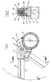
- Fig. 1 eine Seitenansicht einer Zinkenbefestigung einer Bodenbearbeitungsmaschine nach der Erfindung, teilweise im Schnitt,
- Fig. 2 einen Schnitt nach der Linie II-II in Fig. 1,
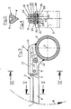
- Fig. 3 eine Ansicht ähnlich Fig. 1 einer zweiten Ausführung der Messerbefestigung einer Bodenbearbeitungsmaschine nach der Erfindung,
- Fig. 4 einen Schnitt nach der Linie IV-IV in Fig. 3, und
- Fig. 5 einen Schnitt nach der Linie V-V in Fig. 3.
- 1 is a side view of a tine attachment of a tillage machine according to the invention, partly in section,
- 2 shows a section along the line II-II in FIG. 1,
- 3 is a view similar to FIG. 1 of a second embodiment of the knife attachment of a tillage machine according to the invention,
- Fig. 4 is a section along the line IV-IV in Fig. 3, and
- 5 shows a section along the line VV in Fig. 3rd
Die in der Zeichnung lediglich mit den für die vorliegende Erfindung wesentlichen Teilen veranschaulichte Bodenbearbeitungsmaschine umfaßt im einzelnen eine an einem nicht dargestellten Maschinengestell um eine Achse (1) drehbar gelagerte, im Bodenbearbeitungsbetrieb angetriebene Welle (2), die üblicherweise mit einer Vielzahl von Werkzeugen (3) bestückt ist, von denen lediglich ein einzelnes näher veranschaulicht ist. Die Ausbildung der Werkzeuge (3), ihre Ausrichtung zur Welle (2) sowie die Anzahl und die Verteilung der Werkzeuge auf der Welle hängen von der Art der Bodenbearbeitung ab und sind in vielfältigen Ausführungsformen bekannt. Die Werkzeuge (3) haben beispielsweise wie dargestellt die Form eines langgestreckten, im wesentlichen geraden Zinkens oder die Form von Mulch- oder Fräsmessern oder für sonstige Arbeiten wie Hackarbeiten geeignete Formen.The soil cultivation machine illustrated in the drawing only with the parts essential to the present invention comprises in particular a shaft (2), which is rotatably mounted about an axis (1) on a machine frame (not shown) and which is usually driven with a large number of tools (3 ), of which only a single one is illustrated in more detail. The design of the tools (3), their orientation to the shaft (2) and the number and distribution of the tools on the shaft depend on the type of tillage and are known in a wide variety of embodiments. As shown, the tools (3) have, for example, the shape of an elongated, essentially straight tine or the shape of mulching or milling knives or shapes suitable for other work such as chopping.
Bei dem als Werkzeug (3) dargestellten geraden Zinken ist der Arbeitsteil (4) auf seiner in die Drehrichtung (5) weisenden Seite keilförmig ausgebildet, rückseitig mit einer längslaufenden Ausnehmung (6) versehen und am freien Ende mit einem Schrägabschnitt (7) ausgebildet, durch den eine Art Freischneidwinkel gebildet wird. Der Arbeitsteil (4) geht in einen Befestigungsteil (8) über, und der Übergangsbereich (9) kann bei Bedarf als Sollbruchstelle ausgebildet sein, wenn zusätzlich zu oder anstelle von einer Überlastsicherung für die Welle (2) eine Überlastsicherung für die Einzelwerkzeuge gewünscht ist.In the case of the straight tine shown as a tool (3), the working part (4) is wedge-shaped on its side pointing in the direction of rotation (5), provided on the back with a longitudinal recess (6) and formed at the free end with an inclined section (7), through which a kind of clearance angle is formed. The working part (4) merges into a fastening part (8), and the transition region (9) can, if necessary, be designed as a predetermined breaking point, if in addition to or instead of one Overload protection for the shaft (2) An overload protection for the individual tools is desired.
Zur Festlegung des Werkzeugs (3) auf der Welle (2) ist letztere mit einem gesonderten Halteteil (10) je Werkzeug (3) versehen, das als eine den Befestigungsteil (8) des Werkzeugs (3) aufnehmende, im wesentlichen U-förmige und an Endbereichen ihrer Seitenschenkel (11,12) an der Welle (2) angeschweißte Tasche ausgebildet ist. Der Querschenkel (13) der U-förmigen Tasche (10) bietet innenseitig eine Anschlagfläche (14) dar, die in Eingriff mit einer Widerlagerfläche (14′) am Befestigungsteil (8) des Werkzeugs (3) dessen Betriebsstellung definiert. Die Tasche (10) umfaßt einen Querzapfen (15), der die Seitenschenkel (11, 12) der Tasche (10) durchgreift und mit deren Außenseite verschweißt ist.To fix the tool (3) on the shaft (2), the latter is provided with a separate holding part (10) for each tool (3), which as a substantially U-shaped and the receiving part (8) of the tool (3) a pocket welded to the shaft (2) is formed at end regions of its side legs (11, 12). The cross leg (13) of the U-shaped pocket (10) offers an inside stop surface (14) which defines its operating position in engagement with an abutment surface (14 ') on the fastening part (8) of the tool (3). The pocket (10) comprises a cross pin (15) which passes through the side legs (11, 12) of the pocket (10) and is welded to the outside thereof.
Das wellenseitige Ende des Befestigungsteils (8) des Werkzeugs (3) ist als auf den Querzapfen (15) aufsetz- bzw. aufhängbarer Haken (16) ausgebildet, der in Betriebsstellung des Werkzeugs (3) den Querzapfen (15) auf seiner der Welle (2) abgewandten Seite mit einem annähernd 180° betragenden Umstreckungswinkel umgreift und das Werkzeug (3) gegen Verlagerungen in dessen Längsrichtung sichert. Der Haken (16) ist in einer in Fig. 1 in gestrichelten Linen veranschaulichten Ansatzstellung auf den Querzapfen (15) aufsetzbar und in dieser auch von diesem abnehmbar, wobei in der Ansatzstellung das Werkzeug (3) eine gegenüber der in Fig. 1 und 3 ausgezogenen Linien veranschaulichten Betriebsstellung eine entgegen der Betriebsdrehrichtung (5) der Welle (2) voreilend verschwenkte Ausrichtung aufweist. Der Schwenkwinkel zwischen der Ansatz- und der Betriebsstellung des Werkzeugs (3) kann dabei den Betrag von etwa 30° bis 60° haben.The shaft-side end of the fastening part (8) of the tool (3) is designed as a hook (16) which can be placed or suspended on the cross pin (15) and which, in the operating position of the tool (3), has the cross pin (15) on its shaft ( 2) engages around the opposite side with an angle of extension of approximately 180 ° and secures the tool (3) against displacements in its longitudinal direction. The hook (16) can be placed on the cross pin (15) in an attachment position illustrated in dashed lines in FIG. 1 and can also be removed from it in the attachment position, the tool (3) in the attachment position being one compared to that in FIGS. 1 and 3 Solid lines illustrate the operating position, which has an orientation that is pivoted ahead of the operating direction of rotation (5) of the shaft (2). The swivel angle between the starting position and the operating position of the tool (3) can amount to approximately 30 ° to 60 °.
Zwischen den Seitenschenkeln (11,12) der Tasche (10) und dem Befestigungsteil (8) des Werkzeugs (3) ist eine Rastarretie rung vorgesehen, die das Werkzeug (3) im Zusammenwirken mit den übrigen in Eingriff befindlichen Teilen der Werkzeugbefestigung in seiner Betriebsstellung fixiert. Die Rastarretierung bei der Ausführung nach Fig. 1 wird von in Querrichtung zum Werkzeug (3) vorspringenden Rastnocken (17,18) und diesen in Betriebsstellung des Werkzeugs (3) gegenüberliegenden, in Querrichtung zurückspringenden Rastausnehmungen (19,20) gebildet, die in Betriebsstellung des Werkzeugs (3) paarweise in Rasteingriff stehen. Die Rastvorsprünge (17,18) sind an dem Befestigungsteil (8) zugewandten Innenseiten der Seitenschenkel (11,12) der Tasche (10) angeordnet, wobei sie bei dem Beispiel nach Fig. 1 als durch Prägen gebildeten Sicken ausgebildet sind. Statt dessen können sie auch von angeformten Nocken, z.B. bei Halteteilen (10) aus Guß, oder von angesetzten Rastgliedern wie den Enden von Schraubenbolzen, von Nietköpfen oder dgl. oder auch von Bohrlöchern gebildet sein. Im letzteren Falle besteht die Möglichkeit ihrer Anbringung vor Anschweißen der Tasche (10) an der Welle (2).There is a locking device between the side legs (11, 12) of the pocket (10) and the fastening part (8) of the tool (3) tion provided that fixes the tool (3) in cooperation with the other engaged parts of the tool attachment in its operating position. 1 is formed by locking cams (17, 18) projecting in the transverse direction to the tool (3) and locking recesses (19, 20) opposite them in the operating position of the tool (3) and in the operating position of the tool (3) are engaged in pairs. The locking projections (17, 18) are arranged on the inside of the side legs (11, 12) of the pocket (10) facing the fastening part (8), in the example according to FIG. 1 they are formed as beads formed by embossing. Instead, they can also be formed by integrally formed cams, for example in the case of holding parts (10) made of cast iron, or by attached locking members such as the ends of screw bolts, rivet heads or the like, or also by drilled holes. In the latter case, it is possible to attach it before welding the pocket (10) to the shaft (2).
Die Rastvorsprünge (17,18) greifen bei dem Beispiel nach Fig. 1 und 2 in Rastausnehmungen (19,20), die in Längsrichtung des Werkzeugs (3) verlaufenden Abschrägungen von Seitenflächenbereichen entlang der der Widerlagerfläche (14′) abgewandten Vorderfläche (14˝) des Befestigungsteils (8) gebildet sind. Anstelle dieser bevorzugten Ausbildung der Rastausnehmungen (19,20), können die Rastausnehmungen auch von im Umriß an die Rastvorsprünge angepaßten Einsenkungen gebildet sein. Die dargestellte Ausbildung der Rastausnehmungen (19,20) hat jedoch den Vorteil, daß sie zugleich Auflauframpen bilden, die bei der Überführung eines Werkzeugs (3) aus der Betriebsstellung in die Ansetzstellung in Funktion treten und das Überwinden der Rastarretierung erleichtern. Eine derartige Erleichterung ist allerdings auch dadurch möglich, daß die Rastvorsprünge (17,18) und/oder die Rastausnehmungen (19,20) jeweils randseitige Abschrägungen als Auflauframpen aufweisen, die sich beispielsweise bei von Sicken gebildeten Rastausnehmungen durch den Prägevorgang praktisch von selbst ergeben.The locking projections (17, 18) engage in the example according to FIGS. 1 and 2 in locking recesses (19, 20), the bevels in the longitudinal direction of the tool (3) from side surface areas along the front surface (14 ') facing away from the abutment surface (14') ) of the fastening part (8) are formed. Instead of this preferred embodiment of the locking recesses (19, 20), the locking recesses can also be formed by depressions which are adapted in outline to the locking projections. The illustrated design of the locking recesses (19, 20) has the advantage, however, that they also form run-up ramps which come into operation when a tool (3) is transferred from the operating position into the attachment position and make it easier to overcome the locking mechanism. Such a relief is also possible, however, in that the latching projections (17, 18) and / or the latching recesses (19, 20) are each on the edge Have bevels as run-up ramps which, for example in the case of latching recesses formed by beads, practically result automatically from the embossing process.
Im Unterschied zur Ausführung der Rastarretierung beim Ausführungsbeispiel nach Fig. 1 und 2 wird die Rastarretierung beim Ausführungsbeispiel nach Fig. 3 und 4 von Rastausnehmungen (21,22) an den Innenseiten der Seitenschenkel (11,12) der Tasche (10) und von Rastvorsprüngen (23,24) an den Seitenflächen des Befestigungsteils (8) des Werkzeugs (3) gebildet. Dies hat den Vorteil, daß bei einem Erneuern des Werkzeugs (3) aus Gründen allgemeinen Verschleisses auch die Rastvorsprünge (23,24) mit ausgewechselt werden, so daß an den Rastvorsprüngen auftretender Verschleiß mitbehoben wird.In contrast to the design of the locking device in the embodiment according to FIGS. 1 and 2, the locking device in the embodiment according to FIGS. 3 and 4 is provided by locking recesses (21, 22) on the inside of the side legs (11, 12) of the pocket (10) and by locking projections (23, 24) on the side surfaces of the fastening part (8) of the tool (3). This has the advantage that when the tool (3) is replaced, for reasons of general wear, the locking projections (23, 24) are also replaced, so that wear occurring on the locking projections is also eliminated.
Die Seitenschenkel (11,12) der Tasche (10) sind im Bereich der Rastarretierungsstellen vorteilhaft federelastisch ausweichbar und nehmen in Rastarretierungsstellung des Werkzeugs (3) vorzugsweise eine federeleastisch voneinander abgespreizte Klemmstellung ein mit der Folge, daß die Vorsprünge und Ausnehmungen der Rastarretierung in der Betriebsstellung des Werkzeugs (3) unter Vorspannung in wechselseitigem Eingriff stehen und so eine unerwünschte Werkzeuglose vermieden ist. Gleichzeitig ergibt sich aus dieser Vorspannung eine Nachstellwirkung. Dies wird besonders begünstigt, wenn neben der Verwendung von federelastischen Materialien für die Wandung der Tasche (10) die Rastarretierungsstellen einen möglichst großen Abstand vom Querschenkel (13) der Tasche (10) und/oder von dem in der Tasche (10) angeordneten Querzapfen (15) haben, so daß sich ein möglichst großer freier Federweg ergibt. Dies gilt für beide Ausführungen nach Fig. 1, 2 und Fig. 3, 4, wobei zu letzterer noch anzumerken ist, daß die Rastausnehmungen (21,22) von durch Prägen gebildeten, annähernd kreisförmigen Einsenkungen gebildet sind, und die Rastvorsprünge von an die Seitenflächen des Befestigungsteils (8) des Werkzeugs (S) angeformten, z.B. angeschmiedeten Nocken gebildet sind, deren Umriß an den der Einsenkungen angepaßt ist.The side legs (11, 12) of the pocket (10) are advantageously resiliently deflectable in the area of the locking locking points and, in the locking locking position of the tool (3), preferably assume a spring-elastic spread-apart clamping position, with the result that the projections and recesses of the locking lock in the operating position of the tool (3) are in mutual engagement under pretension, thus avoiding unwanted toollessness. At the same time, this pretension results in an adjustment effect. This is particularly favored if, in addition to the use of spring-elastic materials for the wall of the pocket (10), the locking arresting points are spaced as far as possible from the transverse leg (13) of the pocket (10) and / or from the transverse pin arranged in the pocket (10) ( 15), so that the largest possible free travel results. This applies to both versions according to FIGS. 1, 2 and 3, 4, with the latter also noting that the latching recesses (21, 22) are formed by approximately circular depressions formed by embossing, and the latching projections from the side surfaces of the fastening part (8) of the tool (S) are formed, for example forged cams, the outline of which is adapted to that of the depressions.
Der Befestigungsteil (8) des Werkzeugs (3) beim Ausführungsbeispiel nach Fig. 1 und 2 weist an seinen Seitenflächen angrenzend an die Widerlagerfläche (14′) zumindest bereichsweise Abschrägungen (25,26) auf, die als Auflauframpen fungieren, wenn ein Werkzeug aus seiner Ansatzstellung in die Betriebsstellung verschwenkt wird und dabei die Rastarretierung zu überwinden hat. Bei der Ausführung nach Fig. 1 und 2 bilden die Rastausnehmungen (19,20) die Auflauframpen an der anderen Seite des Befestigungsteils (8), das aber auch bei der Ausführung nach Fig. 3 und 4 mit lediglich als Auflauframpen dienenden Abschrägungen (27,28) an der Stelle der Rastausnehmungen (19,20) der Ausführung nach Fig. 1 und 2 versehen sein kann.The fastening part (8) of the tool (3) in the embodiment of FIGS. 1 and 2 has on its side surfaces adjacent to the abutment surface (14 ') at least in some areas bevels (25, 26) which act as run-up ramps when a tool is out of it Approach position is pivoted into the operating position and has to overcome the locking mechanism. 1 and 2, the locking recesses (19, 20) form the run-up ramps on the other side of the fastening part (8), but this also in the embodiment according to FIGS. 3 and 4 with bevels serving only as run-up ramps (27, 28) can be provided at the location of the recesses (19, 20) of the embodiment according to FIGS. 1 and 2.
An seinen beiden, den Seitenschenkeln (11,12) der Tasche (10) zugewandten Seitenflächen ist das Werkzeug (3) im Bereich seines Befestigungsteils (8) mit rippenförmigen Schutzvorsprüngen (29,30) versehen, die die in Betriebsdrehrichtung (5) vorderen Schmalseiten (31,32) der Seitenschenkel zumindest in jenem Bereich abdecken, in dem die Möglichkeit eines Eingriffs in den Boden besteht. Die sich entlang den Schmalseiten erstreckenden Schutzteile (29,30) verhindern Verschleiß an den Taschen (10), wohingegen Verschleiß an den Schutzteilen ohne Bedeutung ist, da die Werkzeuge (3) wegen sonstigen Verschleißes ohnehin von Zeit zu Zeit der Auswechslung bedürfen.On its two side surfaces (11, 12) of the pocket (10) facing the tool (3) in the region of its fastening part (8) is provided with rib-shaped protective projections (29, 30) which protect the narrow sides at the front in the direction of rotation (5) (31,32) cover the side legs at least in the area where there is a possibility of intervention in the ground. The protective parts (29, 30) extending along the narrow sides prevent wear on the pockets (10), whereas wear on the protective parts is irrelevant, since the tools (3) need to be replaced anyway from time to time due to other wear.
Die Tasche (10) ist ein außerordentlich formstabiles Bauteil, das dem Befestigungsteil (8) des Werkzeugs einen festen Halt vermittelt und hohe Belastungen verformungsfrei aufnehmen kann. In dieser Tasche (10) hat das Werkzeug (3) einen im wesentlichen spielfreien Sitz, den es während aller Betriebsbelastungen beibehält. Für das Auswechseln eines Werkzeugs genügt ein kräftiger Schlag auf dessen der Drehrichtung (5) abgewandte Rückseite, um es in die Ansatzstellung zu überführen und abnehmen zu können. Für die Ausführung eines solchen Schlages bietet sich der neue Zinken an, wohingegen der alte Zinken für einen Schlag auf einen angesetzten neuen Zinken Verwendung finden kann, so daß besondere Hilfswerkzeuge entbehrlich sind.The pocket (10) is an extremely dimensionally stable component, which gives the fastening part (8) of the tool a firm hold and can absorb high loads without deformation. In this pocket (10), the tool (3) has an essentially play-free seat, which it has during all Maintains operating loads. To replace a tool, a strong blow on the back facing away from the direction of rotation (5) is sufficient to transfer it to the attachment position and remove it. The new tine is suitable for carrying out such a stroke, whereas the old tine can be used for a stroke on an attached new tine, so that special auxiliary tools are unnecessary.
Claims (21)
Applications Claiming Priority (2)
| Application Number | Priority Date | Filing Date | Title |
|---|---|---|---|
| DE8905025U | 1989-04-21 | ||
| DE8905025U DE8905025U1 (en) | 1989-04-21 | 1989-04-21 | tillage machine |
Publications (3)
| Publication Number | Publication Date |
|---|---|
| EP0393337A2 true EP0393337A2 (en) | 1990-10-24 |
| EP0393337A3 EP0393337A3 (en) | 1991-06-05 |
| EP0393337B1 EP0393337B1 (en) | 1994-06-01 |
Family
ID=6838517
Family Applications (1)
| Application Number | Title | Priority Date | Filing Date |
|---|---|---|---|
| EP90104104A Expired - Lifetime EP0393337B1 (en) | 1989-04-21 | 1990-03-02 | Groundworking tool |
Country Status (5)
| Country | Link |
|---|---|
| US (1) | US5069295A (en) |
| EP (1) | EP0393337B1 (en) |
| AT (1) | ATE106177T1 (en) |
| DE (2) | DE8905025U1 (en) |
| ES (1) | ES2058638T3 (en) |
Cited By (1)
| Publication number | Priority date | Publication date | Assignee | Title |
|---|---|---|---|---|
| EP2674028A3 (en) * | 2012-06-14 | 2015-01-07 | Mayer Verwaltungs GmbH & Co. KG | Cutting blade holder |
Families Citing this family (3)
| Publication number | Priority date | Publication date | Assignee | Title |
|---|---|---|---|---|
| DE29707781U1 (en) | 1997-04-30 | 1997-09-25 | Rau, Willy, 73230 Kirchheim | Soil cultivation machine for agriculture |
| DE29822809U1 (en) * | 1998-12-22 | 2000-05-11 | RDZ Dutzi GmbH, 76698 Ubstadt-Weiher | Tine rotor for a tillage implement |
| FR2819145B1 (en) * | 2001-01-11 | 2004-01-30 | Kuhn Sa | AGRICULTURAL SOIL WORKING MACHINE COMPRISING TOOLS WITH QUICK FASTENING |
Citations (8)
| Publication number | Priority date | Publication date | Assignee | Title |
|---|---|---|---|---|
| DE311701C (en) * | ||||
| DE538033C (en) * | 1928-01-29 | 1931-11-11 | Siemens Schuckertwerke Akt Ges | Attachment of the work equipment in soil tillage machines with rotating tools |
| US2054129A (en) * | 1935-05-24 | 1936-09-15 | Kelsey Cadwallader Washburn | Agricultural implement |
| FR865988A (en) * | 1939-06-12 | 1941-06-11 | Grunder & Co A G A | Tool and milling cutter for soil loosening |
| FR2208589A1 (en) * | 1972-12-04 | 1974-06-28 | Lely Nv C Van Der | |
| FR2330295A1 (en) * | 1975-11-07 | 1977-06-03 | Huard Ucf | Fixing for rotary hoe blades to hub - using two cutouts at right angles fitting over bolts holding clamp plate in position |
| DE8532161U1 (en) * | 1985-11-14 | 1986-01-23 | Maschinenfabrik Rau Gmbh, 7315 Weilheim | Tine rotor for agricultural tillage |
| EP0223595A2 (en) * | 1985-11-20 | 1987-05-27 | Kobashi Kogyo Co., Ltd. | Cutter mounting structure for a rotary tilling device |
Family Cites Families (8)
| Publication number | Priority date | Publication date | Assignee | Title |
|---|---|---|---|---|
| US289797A (en) * | 1883-12-11 | Plow-point | ||
| US885019A (en) * | 1907-08-28 | 1908-04-21 | George Conley | Colter. |
| US1586151A (en) * | 1922-05-08 | 1926-05-25 | Daniel Boone Mining Machine Co | Bit or cutting tool |
| US2515268A (en) * | 1946-07-05 | 1950-07-18 | Harry J Seaman | Rotary soil-working implement |
| US2778291A (en) * | 1954-10-19 | 1957-01-22 | James F Kerns | Rotary renovator |
| US3589452A (en) * | 1969-12-10 | 1971-06-29 | Rex Chainbelt Inc | Tine-mounting assembly |
| US3702638A (en) * | 1971-01-18 | 1972-11-14 | Raygo Inc | Earth working rotor with improved tines |
| US4098013A (en) * | 1976-08-18 | 1978-07-04 | Charles Wayne Hemphill | Digging tooth with replaceable cutting edge |
-
1989
- 1989-04-21 DE DE8905025U patent/DE8905025U1/en not_active Expired - Lifetime
-
1990
- 1990-03-02 EP EP90104104A patent/EP0393337B1/en not_active Expired - Lifetime
- 1990-03-02 AT AT90104104T patent/ATE106177T1/en not_active IP Right Cessation
- 1990-03-02 DE DE59005873T patent/DE59005873D1/en not_active Expired - Fee Related
- 1990-03-02 ES ES90104104T patent/ES2058638T3/en not_active Expired - Lifetime
- 1990-04-09 US US07/506,980 patent/US5069295A/en not_active Expired - Fee Related
Patent Citations (8)
| Publication number | Priority date | Publication date | Assignee | Title |
|---|---|---|---|---|
| DE311701C (en) * | ||||
| DE538033C (en) * | 1928-01-29 | 1931-11-11 | Siemens Schuckertwerke Akt Ges | Attachment of the work equipment in soil tillage machines with rotating tools |
| US2054129A (en) * | 1935-05-24 | 1936-09-15 | Kelsey Cadwallader Washburn | Agricultural implement |
| FR865988A (en) * | 1939-06-12 | 1941-06-11 | Grunder & Co A G A | Tool and milling cutter for soil loosening |
| FR2208589A1 (en) * | 1972-12-04 | 1974-06-28 | Lely Nv C Van Der | |
| FR2330295A1 (en) * | 1975-11-07 | 1977-06-03 | Huard Ucf | Fixing for rotary hoe blades to hub - using two cutouts at right angles fitting over bolts holding clamp plate in position |
| DE8532161U1 (en) * | 1985-11-14 | 1986-01-23 | Maschinenfabrik Rau Gmbh, 7315 Weilheim | Tine rotor for agricultural tillage |
| EP0223595A2 (en) * | 1985-11-20 | 1987-05-27 | Kobashi Kogyo Co., Ltd. | Cutter mounting structure for a rotary tilling device |
Cited By (1)
| Publication number | Priority date | Publication date | Assignee | Title |
|---|---|---|---|---|
| EP2674028A3 (en) * | 2012-06-14 | 2015-01-07 | Mayer Verwaltungs GmbH & Co. KG | Cutting blade holder |
Also Published As
| Publication number | Publication date |
|---|---|
| EP0393337B1 (en) | 1994-06-01 |
| ES2058638T3 (en) | 1994-11-01 |
| US5069295A (en) | 1991-12-03 |
| EP0393337A3 (en) | 1991-06-05 |
| DE8905025U1 (en) | 1989-12-14 |
| ATE106177T1 (en) | 1994-06-15 |
| DE59005873D1 (en) | 1994-07-07 |
Similar Documents
| Publication | Publication Date | Title |
|---|---|---|
| DE69636251T2 (en) | WEAR ELEMENT FOR A CUTTING CARD OF A BAGGER | |
| DE3879756T2 (en) | CHUCK, ESPECIALLY FOR MACHINE TOOLS. | |
| DE102006019069A1 (en) | comminution device | |
| DE3513670C2 (en) | Arrangement for fastening sleeve-shaped teeth | |
| EP0634218B1 (en) | Rotor for a crushing machine | |
| DD203768A5 (en) | MEISSELANORDNUNG, ESPECIALLY FOR KOHLENHOBEL AND DERGL. | |
| DE202009001814U1 (en) | Milling tooth for a trench wall cutter | |
| EP0393337B1 (en) | Groundworking tool | |
| EP3362603B1 (en) | Skid segment for an edge protection on a road milling machine and edge protection for a road milling machine | |
| DE2160190A1 (en) | Cutting tool | |
| DE69510581T2 (en) | Quick change device for earth moving machine and the like | |
| DE19630642C2 (en) | Tool for a cutting machine | |
| DE4109783A1 (en) | Bucket for earth moving machine - is held in place by hydraulic cylinders which hold attachment hooks in engagement | |
| DE2504859C2 (en) | Tines for a tillage machine | |
| EP3254544B1 (en) | Soil cultivation device | |
| DE69505090T2 (en) | Tool attachment device for a machine cutting wheel | |
| EP3235358A1 (en) | Plough point for use in a metering system for soil cultivation | |
| EP1651818A1 (en) | Arrangement for fixing an add-on piece, e.g. an excavator shovel, to a boom of a shovel or a vehicle in a replaceable manner | |
| DE3616759C2 (en) | ||
| DE9310886U1 (en) | knife | |
| DE69216919T2 (en) | Needle for knitting machine | |
| DE60306870T2 (en) | Tool holder for a soil cultivator and tool | |
| DE1575800A1 (en) | Device for the detachable fastening of parts on spline shafts, especially of dobby machines | |
| DE3209391A1 (en) | CUTTING TOOL FOR A SLEEVE CHAIN OR A SLEEVE BELT | |
| DE69810893T2 (en) | Device for determining a bisector |
Legal Events
| Date | Code | Title | Description |
|---|---|---|---|
| PUAI | Public reference made under article 153(3) epc to a published international application that has entered the european phase |
Free format text: ORIGINAL CODE: 0009012 |
|
| AK | Designated contracting states |
Kind code of ref document: A2 Designated state(s): AT BE CH DE DK ES FR GB IT LI LU NL |
|
| 17P | Request for examination filed |
Effective date: 19901016 |
|
| PUAL | Search report despatched |
Free format text: ORIGINAL CODE: 0009013 |
|
| AK | Designated contracting states |
Kind code of ref document: A3 Designated state(s): AT BE CH DE DK ES FR GB IT LI LU NL |
|
| 17Q | First examination report despatched |
Effective date: 19910912 |
|
| GRAA | (expected) grant |
Free format text: ORIGINAL CODE: 0009210 |
|
| AK | Designated contracting states |
Kind code of ref document: B1 Designated state(s): AT DE ES FR GB IT NL |
|
| REF | Corresponds to: |
Ref document number: 106177 Country of ref document: AT Date of ref document: 19940615 Kind code of ref document: T |
|
| REF | Corresponds to: |
Ref document number: 59005873 Country of ref document: DE Date of ref document: 19940707 |
|
| ITF | It: translation for a ep patent filed | ||
| ET | Fr: translation filed | ||
| GBT | Gb: translation of ep patent filed (gb section 77(6)(a)/1977) |
Effective date: 19940811 |
|
| REG | Reference to a national code |
Ref country code: ES Ref legal event code: FG2A Ref document number: 2058638 Country of ref document: ES Kind code of ref document: T3 |
|
| PLBE | No opposition filed within time limit |
Free format text: ORIGINAL CODE: 0009261 |
|
| STAA | Information on the status of an ep patent application or granted ep patent |
Free format text: STATUS: NO OPPOSITION FILED WITHIN TIME LIMIT |
|
| 26N | No opposition filed | ||
| PGFP | Annual fee paid to national office [announced via postgrant information from national office to epo] |
Ref country code: GB Payment date: 19970226 Year of fee payment: 8 |
|
| PGFP | Annual fee paid to national office [announced via postgrant information from national office to epo] |
Ref country code: ES Payment date: 19970320 Year of fee payment: 8 |
|
| PGFP | Annual fee paid to national office [announced via postgrant information from national office to epo] |
Ref country code: AT Payment date: 19970326 Year of fee payment: 8 |
|
| PG25 | Lapsed in a contracting state [announced via postgrant information from national office to epo] |
Ref country code: GB Free format text: LAPSE BECAUSE OF NON-PAYMENT OF DUE FEES Effective date: 19980302 Ref country code: AT Free format text: LAPSE BECAUSE OF NON-PAYMENT OF DUE FEES Effective date: 19980302 |
|
| PG25 | Lapsed in a contracting state [announced via postgrant information from national office to epo] |
Ref country code: ES Free format text: LAPSE BECAUSE OF EXPIRATION OF PROTECTION Effective date: 19980303 |
|
| GBPC | Gb: european patent ceased through non-payment of renewal fee |
Effective date: 19980302 |
|
| PGFP | Annual fee paid to national office [announced via postgrant information from national office to epo] |
Ref country code: FR Payment date: 19990330 Year of fee payment: 10 |
|
| PGFP | Annual fee paid to national office [announced via postgrant information from national office to epo] |
Ref country code: NL Payment date: 19990331 Year of fee payment: 10 |
|
| PGFP | Annual fee paid to national office [announced via postgrant information from national office to epo] |
Ref country code: DE Payment date: 19990528 Year of fee payment: 10 |
|
| REG | Reference to a national code |
Ref country code: ES Ref legal event code: FD2A Effective date: 20000201 |
|
| PG25 | Lapsed in a contracting state [announced via postgrant information from national office to epo] |
Ref country code: NL Free format text: LAPSE BECAUSE OF NON-PAYMENT OF DUE FEES Effective date: 20001001 |
|
| PG25 | Lapsed in a contracting state [announced via postgrant information from national office to epo] |
Ref country code: FR Free format text: LAPSE BECAUSE OF NON-PAYMENT OF DUE FEES Effective date: 20001130 |
|
| NLV4 | Nl: lapsed or anulled due to non-payment of the annual fee |
Effective date: 20001001 |
|
| REG | Reference to a national code |
Ref country code: FR Ref legal event code: ST |
|
| PG25 | Lapsed in a contracting state [announced via postgrant information from national office to epo] |
Ref country code: DE Free format text: LAPSE BECAUSE OF NON-PAYMENT OF DUE FEES Effective date: 20010103 |
|
| PG25 | Lapsed in a contracting state [announced via postgrant information from national office to epo] |
Ref country code: IT Free format text: LAPSE BECAUSE OF NON-PAYMENT OF DUE FEES;WARNING: LAPSES OF ITALIAN PATENTS WITH EFFECTIVE DATE BEFORE 2007 MAY HAVE OCCURRED AT ANY TIME BEFORE 2007. THE CORRECT EFFECTIVE DATE MAY BE DIFFERENT FROM THE ONE RECORDED. Effective date: 20050302 |