EP0393217A1 - Standfuss - Google Patents
Standfuss Download PDFInfo
- Publication number
- EP0393217A1 EP0393217A1 EP89106963A EP89106963A EP0393217A1 EP 0393217 A1 EP0393217 A1 EP 0393217A1 EP 89106963 A EP89106963 A EP 89106963A EP 89106963 A EP89106963 A EP 89106963A EP 0393217 A1 EP0393217 A1 EP 0393217A1
- Authority
- EP
- European Patent Office
- Prior art keywords
- stand according
- knobs
- head
- plastic
- shaft
- Prior art date
- Legal status (The legal status is an assumption and is not a legal conclusion. Google has not performed a legal analysis and makes no representation as to the accuracy of the status listed.)
- Granted
Links
- NJPPVKZQTLUDBO-UHFFFAOYSA-N novaluron Chemical compound C1=C(Cl)C(OC(F)(F)C(OC(F)(F)F)F)=CC=C1NC(=O)NC(=O)C1=C(F)C=CC=C1F NJPPVKZQTLUDBO-UHFFFAOYSA-N 0.000 claims description 12
- 239000013536 elastomeric material Substances 0.000 claims description 3
- 230000000149 penetrating effect Effects 0.000 claims description 3
- 238000013016 damping Methods 0.000 abstract description 5
- 239000000463 material Substances 0.000 description 6
- 230000002349 favourable effect Effects 0.000 description 4
- 238000005406 washing Methods 0.000 description 4
- 238000004519 manufacturing process Methods 0.000 description 3
- 230000006978 adaptation Effects 0.000 description 2
- 239000006223 plastic coating Substances 0.000 description 2
- 238000004873 anchoring Methods 0.000 description 1
- 230000005540 biological transmission Effects 0.000 description 1
- 238000006073 displacement reaction Methods 0.000 description 1
- 230000000694 effects Effects 0.000 description 1
- 230000035515 penetration Effects 0.000 description 1
- 238000009987 spinning Methods 0.000 description 1
Images

Classifications
-
- A—HUMAN NECESSITIES
- A47—FURNITURE; DOMESTIC ARTICLES OR APPLIANCES; COFFEE MILLS; SPICE MILLS; SUCTION CLEANERS IN GENERAL
- A47B—TABLES; DESKS; OFFICE FURNITURE; CABINETS; DRAWERS; GENERAL DETAILS OF FURNITURE
- A47B91/00—Feet for furniture in general
-
- D—TEXTILES; PAPER
- D06—TREATMENT OF TEXTILES OR THE LIKE; LAUNDERING; FLEXIBLE MATERIALS NOT OTHERWISE PROVIDED FOR
- D06F—LAUNDERING, DRYING, IRONING, PRESSING OR FOLDING TEXTILE ARTICLES
- D06F39/00—Details of washing machines not specific to a single type of machines covered by groups D06F9/00 - D06F27/00
- D06F39/12—Casings; Tubs
- D06F39/125—Supporting arrangements for the casing, e.g. rollers or legs
-
- F—MECHANICAL ENGINEERING; LIGHTING; HEATING; WEAPONS; BLASTING
- F16—ENGINEERING ELEMENTS AND UNITS; GENERAL MEASURES FOR PRODUCING AND MAINTAINING EFFECTIVE FUNCTIONING OF MACHINES OR INSTALLATIONS; THERMAL INSULATION IN GENERAL
- F16F—SPRINGS; SHOCK-ABSORBERS; MEANS FOR DAMPING VIBRATION
- F16F1/00—Springs
- F16F1/36—Springs made of rubber or other material having high internal friction, e.g. thermoplastic elastomers
- F16F1/373—Springs made of rubber or other material having high internal friction, e.g. thermoplastic elastomers characterised by having a particular shape
- F16F1/376—Springs made of rubber or other material having high internal friction, e.g. thermoplastic elastomers characterised by having a particular shape having projections, studs, serrations or the like on at least one surface
Definitions
- the invention relates to a pedestal with a threaded shaft and a head formed on this end and enclosed by a plastic sheath.
- a stand of the type mentioned is known for example from DE-PS 28 20 481 and is used, for example, for storing a household machine, in particular a washing machine.
- feet for washing machines must be able to dampen vibrations in order to influence the transfer of the forces that occur during washing or spinning to the floor. Furthermore, such feet must have sufficient strength to be able to safely transmit the forces even under high loads. In addition, with such devices, such as washing machines, there is a risk that the vibrations of the device will cause it to move on the floor, since the Rei exercise between the stand and the floor surface is not large enough.
- the invention has for its object to provide a pedestal of the type mentioned, which ensures a safe stand of a device with a simple structure and inexpensive to manufacture even when vibrations and vibrations occur.
- the invention is achieved in that a plurality of knobs are formed on the base of the base on the plastic casing, the end faces of which are each provided with a dome-shaped recess.
- the stand according to the invention is characterized by a number of considerable advantages. Due to the multiple knobs, the base can also be precisely adjusted to an uneven surface, since the knobs can be deformed separately due to the elasticity of the plastic.
- the dome-shaped recess causes suction or firm suction on a smooth contact surface, so that in addition to the friction that exists between the knobs and the contact surface, holding forces occur due to the suction effect of the knobs.
- Another advantage of the stand according to the invention is that it not only enables adaptation to a non-planar contact surface, but also creates the possibility, due to the deformability of the knobs, of enabling a secure stand on a beveled contact surface.
- the individual knobs are deformed to different degrees, but overall the entire base of the base rests on the base or on the base. Uneven loads, for example with purely metallic Stands or smooth plastic feet can occur and which, in the worst case, would result in a deformation of the shaft are avoided.
- Another advantage of the pedestal according to the invention is that, due to the peg-like protrusions, it offers the possibility of being positively engaged with uneven surfaces, for example joints between floor tiles. This also leads to a considerable increase in the lateral slip resistance of the pedestal, especially on wet surfaces.
- the knobs extend over a certain amount from the base of the base, the knobs ensure sufficient vibration damping even when using a harder, less damping plastic material, since the overall length of the knobs ensures a sufficient material thickness even with a thin cross section of the plastic covering.
- the knobs have a circular cross section. On the one hand, this proves to be particularly favorable for manufacturing reasons, and on the other hand the risk of breakage of the knobs is reduced.
- the recess on the end face of the knob which is essentially dome-shaped, is preferably concave, in the form of a spherical cap.
- each knob is preferably provided with a sharp edge to to ensure the strongest possible connection to the floor surface.
- the sharp-edged design of the edge facilitates the penetration of the knobs in softer floors, for example in the case of floor coverings, in order to bring about a form-fitting connection and slip protection.
- the head is surrounded by the plastic coating already mentioned.
- the head is provided with at least one rib on its free end face. This creates a positive connection between the plastic casing and the material of the head. It proves to be particularly advantageous if a plurality of radial ribs are provided, which are suitable for power transmission in a wide variety of directions, so that the plastic sheathing cannot be moved or moved relative to the head under the loads that occur.
- the head is plate-shaped and has ribs on both sides.
- the head of the pedestal is preferably round, since this can then be produced as a simple turned part.
- the plastic sheathing preferably has a polygonal basic shape, for example a hexagonal shape, in order to offer the possibility of using the entire base Tool, for example a wrench, to rotate relative to the device in order to adjust the height of the base.
- the knobs In a further embodiment of the stand according to the invention, it is also possible to provide the knobs with a triangular cross section, in the middle of which the recess is arranged. It is also possible to design the knobs in the form of ribs which surround the recess. In this case the knobs are essentially reduced to the edge area. It can prove to be expedient to design the ribs, which form the knobs, in the form of equilateral triangles, which are arranged like a honeycomb.
- the manufacture of the pedestal according to the invention can be considerably simplified if it is provided with a central recess which is connected to a plurality of radial recesses is open at least on the head towards the stand.
- both the central recess and the radial recesses can be filled with plastic during the application of the plastic casing, the plastic casing in the area of the base and the anti-rotation device being formed simultaneously in one work step.
- Plastic bolts are then arranged both in the central recess and in the radial recesses.
- both the plastic casing and the plastic bolts are made of an elastomeric material.
- the plastic screw bolt advantageously consists of a "harder” plastic.
- the elastomeric material offers sufficient elasticity and absorbs the vibrations.
- the "harder" plastic of the bolt is stiff enough to transmit the forces, so that the risk of breakage is avoided.
- the possibility is created of considerably increasing the entire contact area, since the elasticity of the knobs avoids the risk of the head kinking relative to the shaft.
- the stand according to the invention comprises a shaft 1 which is provided with an external thread and which is firmly connected to a circular plate-shaped head 2.
- the head 2 can be formed in one piece with the shaft 1, but it is also possible to screw it onto the shaft 1 or to weld it to the latter.
- the head 2 has a plurality of radially arranged ribs 9 on its top and bottom, which ensure a form-fitting connection with a plastic casing 3 which essentially surrounds the entire head 2.
- the plastic sheath as shown in Fig. 2, has a substantially hexagonal cross section, so that it is possible to twist the plastic sheath together with the head 2 and the shaft 1 relative to a device, not shown.
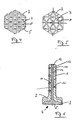
- a plurality of knobs 5 are formed on the base 4 of the base, which, as can be seen in FIG. 1, has an essentially cylindrical one Have structure, and the end face 6 is provided with a dome-shaped recess 7.
- the knobs 5, which are made in one piece with the plastic casing 3, are elastically deformable and can be adapted in a particularly simple manner to unevenness in the floor when the base is set up.
- FIG. 4 shows a bottom view, similar to FIG. 2, in which, compared to the exemplary embodiment shown in FIG. 2, the knobs have a larger diameter.
- 5 shows a further exemplary embodiment, in which the knobs are essentially triangular and are essentially reduced to their edge region or rib region, so that the central recess 7 is likewise essentially triangular.
- the triangular configuration of the ribs is particularly well suited for wet floors, since the recesses 7 are provided with a very large volume.
- FIG. 6 shows in longitudinal section, similar to FIG. 1, a further embodiment of the pedestal according to the invention.
- the shaft 1 provided with a thread 10 has a central recess 13 and a plurality of recesses 14 extending from this central recess 13.
- the central recess 13 is particularly open to the footprint 4 of the foot 2, so that the material for the casing 3 can penetrate into the central recess 13 and the radial recesses 14.
- the finished state is shown in the central recess 13, a central plastic bolt 12 is arranged, which is integrally formed with the plastic casing 3.
- the plastic bolt 12 is formed in one piece with a plurality of radial plastic bolts 11, which extend into the thread 10 and thus act as an anti-rotation device when the shaft 1 is screwed into an internal thread of a metallic holder.
- an additional anti-rotation device is provided, which, however, does not affect the adjustability of the base.
- knobs 5 On the end face 6, the knobs 5 have a sharp-edged edge 8, which, as can be seen in FIG. 2, is circular and serves to form-fit the base with a contact surface, the material of which is softer than the material of the plastic casing connect.
- the stand according to the invention has, on the one hand, due to the plastic coating, sufficient damping of vibrations, on the other hand it is ensured that an adaptation to uneven floors and the like can take place, the knobs at the same time allowing a positive connection with uneven floors.
Landscapes
- Engineering & Computer Science (AREA)
- Textile Engineering (AREA)
- General Engineering & Computer Science (AREA)
- Mechanical Engineering (AREA)
- Vibration Prevention Devices (AREA)
- Snaps, Bayonet Connections, Set Pins, And Snap Rings (AREA)
- Outer Garments And Coats (AREA)
Abstract
Description
- Die Erfindung bezieht sich auf einen Standfuß mit einem mit einem Gewinde versehenen Schaft und einem endseitig an diesem ausgebildeten, von einer Kunststoffummantelung umschlossenen Kopf.
- Ein Standfuß der eingangs genannten Art ist beispielsweise aus der DE-PS 28 20 481 bekannt und dient beispielsweise zur Lagerung einer Haushaltsmaschine, insbesondere einer Waschmaschine.
- Standfüße für Waschmaschinen müssen zum einen in der Lage sein, schwingungsdämpfend zu wirken, um die Übertragung der beim Waschen oder Schleudern auftretenden Kräfte auf den Boden entsprechend zu beeinflussen. Weiterhin müssen derartige Standfüße eine ausreichende Festigkeit aufweisen, um auch bei einer hohen Belastung die Kräfte sicher übertragen zu können. Zudem besteht bei derartigen Geräten, wie beispielsweise Waschmaschinen, die Gefahr, daß die Schwingungen des Gerätes dazu führen, daß dieses auf dem Boden wandert, da die Rei bung zwischen dem Standfuß und der Bodenoberfläche nicht ausreichend groß ist.
- Der Erfindung liegt die Aufgabe zugrunde, einen Standfuß der eingangs genannten Art zu schaffen, weicher bei einfachem Aufbau und kostengünstiger Herstellbarkeit einen sicheren Stand eines Gerätes auch bei Auftreten von Schwingungen und Vibrationen sicherstellt.
- Die Erfindung wird dadurch gelöst, daß an der Standfläche des Standfußes an der Kunststoffummantelung mehrere Noppen ausgebildet sind, deren Stirnflächen jeweils mit einer kalottenförmigen Ausnehmung versehen sind.
- Der erfindungsgemäße Standfuß zeichnet sich durch eine Reihe erheblicher Vorteile aus. Durch die mehreren Noppen kann eine exakte Anpassung des Standfußes auch an eine unebene Oberfläche erfolgen, da die Noppen, bedingt durch die Elastizität des Kunststoffes, jeweils separat verformbar sind. Die kalottenförmige Ausnehmung bewirkt ein Ansaugen oder Festsaugen auf einer glatten Aufstandsfläche, so daß zusätzlich zu der Reibung, welche zwischen den Noppen und der Aufstandsfläche herrscht, Haltekräfte bedingt durch die Ansaugwirkung der Noppen auftreten. Ein weiterer Vorteil des erfindungsgemäßen Standfußes besteht darin, daß dieser nicht nur eine Anpassung an eine nichtebene Aufstandsfläche ermöglicht, sondern, bedingt durch die Verformbarkeit der Noppen, auch die Möglichkeit schafft, einen sicheren Stand auf einer abgeschrägten Aufstandsfläche zu ermöglichen. Dabei werden die einzelnen Noppen in unterschiedlichem Maße verformt, insgesamt ruht jedoch im wesentlichen die gesamte Standfläche des Standfußes auf der Aufstandsfläche oder dem Boden. Ungleichmäßige Belastungen, welche beispielsweise bei rein metallischen Standfüßen oder glatten Kunststoff-Füßen auftreten können und welche im ungünstigen Fall eine Verformung des Schaftes nach sich ziehen würden, werden dabei vermieden.
- Ein weiterer Vorteil des erfindungsgemäßen Standfußes besteht darin, daß dieser, bedingt durch die zapfenartig vorstehenden Noppen, die Möglichkeit bietet, formschlüssig mit Oberflächenunebenheiten, beispielsweise Fugen zwischen Bodenfliesen, in Eingriff gebracht zu werden. Auch dies führt zu einer erheblichen Steigerung der seitlichen Rutschfestigkeit des Standfußes, insbesondere bei nassem Untergrund.
- Da sich erfindungsgemäß die Noppen über einen bestimmten Betrag von der Standfläche des Standfußes aus erstrecken, gewährleisten die Noppen auch bei Verwendung eines härteren, weniger dämpfenden Kunststoffmaterials eine ausreichende Schwingungsdämpfung, da auch bei einem dünnen Querschnitt der Kunststoffummantelung die Gesamtlänge der Noppen eine ausreichende Materialdicke sicherstellt.
- In einer bevorzugten Ausführungsform der Erfindung ist vorgesehen, daß die Noppen einen kreisförmigen Querschnitt aufweisen. Dies erweist sich zum einen aus herstellungstechnischen Gründen als besonders günstig, zum anderen wird die Bruchgefahr der Noppen reduziert.
- Die Ausnehmung an der Stirnfläche der Noppe, welche im wesentlichen kalottenförmig ausgebildet ist, ist bevorzugterweise konkav, in Form einer Kugelkappe ausgebildet.
- Der Rand an der Stirnfläche jeder Noppe ist bevorzugterweise mit einer scharfen Kante versehen, um eine möglichst feste Verbindung mit der Bodenfläche zu gewährleisten. Die scharfkantige Ausbildung des Randes erleichtert bei weicheren Böden, beispielsweise bei Bodenbelägen, das Eindringen der Noppen, um eine formschlüssige Verbindung und Rutschsicherung zu bewirken.
- Bei dem erfindungsgemäßen Standfuß ist der Kopf mit der bereits erwähnten Kunststoffummantelung umgeben. Um eine Verdrehung oder Verschiebung des Kopfes relativ zu der Kunststoffummantelung zu verhindern und um sicherzustellen, daß der Kopf fest mit der Kunststoffummantelung verbunden ist, ist es günstig, wenn der Kopf an seiner freien Stirnfläche mit zumindest einer Rippe versehen ist. Diese bewirkt eine formschlüssige Verbindung zwischen der Kunststoffummantelung und dem Material des Kopfes. Dabei erweist es sich als besonders vorteilhaft, wenn mehrere radiale Rippen vorgesehen sind, welche zur Kraftübertragung in verschiedensten Richtungen geeignet sind, so daß die Kunststoffummantelung bei den auftretenden Belastungen nicht relativ zu dem Kopf bewegt oder verschoben werden kann.
- Um den erfindungsgemäßen Standfuß besonders kostengünstig herstellen zu können und um eine feste Verankerung an der Kunststoffummantelung sicherzustellen, erweist es sich als besonders günstig, wenn der Kopf plattenförmig ausgebildet ist und beidseitig mit Rippen versehen ist.
- Bevorzugterweise ist der Kopf des Standfußes rund ausgestaltet, da dieser dann als einfaches Drehteil hergestellt werden kann. Die Kunststoffummantelung weist bevorzugterweise eine vieleckige Grundform auf, beispielsweise eine sechseckige Form, um die Möglichkeit zu bieten, den gesamten Standfuß unter Verwendung eines Werkzeugs, beispielsweise eines Schraubenschlüssels, relativ zu dem Gerät zu verdrehen, um auf diese Weise die Höhe des Standfußes einzustellen.
- In einer weiteren Ausgestaltung des erfindungsgemäßen Standfußes ist es auch möglich, die Noppen mit einem dreieckigen Querschnitt zu versehen, in deren Mitte die Ausnehmung angeordnet ist. Es ist auch möglich, die Noppen in Form von Rippen auszubilden, welche die Ausnehmung umschließen. Die Noppen sind in diesem Falle im wesentlichen auf den Randbereich reduziert. Es kann sich als günstig erweisen, die Rippen, welche die Noppen bilden, in Form gleichseitiger Dreiecke auszubilden, weiche wabenartig angeordnet sind.
- Um auch bei größeren Vibrationen eine sichere Abstützung des Gerätes sicherzustellen, kann es sich als günstig erweisen, im Bereich des Gewindes eine Verdrehsicherung auszubilden, welche ein Verdrehen der Standfüße unter den auftretenden Belastungen vermeidet. Dabei kann es sich als besonders günstig erweisen, wenn im Bereich des Schaftes zumindest ein das Gewinde durchdringendes, sich in radialer Richtung erstreckendes Sicherungselement angeordnet ist. Dieses gelangt somit in die Gewindegänge und führt dort zu einem erhöhten Reibungskoeffizienten, durch welchen ein unbeabsichtigtes Verschrauben des Standfußes verhindert wird. Besonders günstig ist es, wenn das Sicherungselement in Form eines den Schaft zumindest zum Teil radial durchdringenden Kunststoffbolzens ausgebildet ist.
- Die Herstellung des erfindungsgemäßen Standfußes kann erheblich vereinfacht werden, wenn dieser mit einer zentrischen Ausnehmung versehen ist, welche mit mehreren radialen Ausnehmungen in Verbindung steht und zu mindest am Kopf zur Standfläche hin offen ist. In diesem Falle können bei der Aufbringung der Kunststoffummantelung sowohl die zentrische Ausnehmung als auch die radialen Ausnehmungen mit Kunststoff gefüllt werden, wobei in einem Arbeitsgang gleichzeitig die Kunststoffummantelung im Bereich des Standfußes als auch die Verdrehsicherung ausgebildet wird. Es sind dann sowohl in der zentrischen Ausnehmung als auch in den radialen Ausnehmungen jeweils Kunststoffbolzen angeordnet.
- In einer besonders günstigen Ausbildung der Erfindung ist vorgesehen, daß sowohl die Kunststoffummantelung als auch die Kunststoffbolzen aus einem elastomeren Material gefertigt sind. Der Kunststoff-Schraubenbolzen besteht vorteilhaft aus einem "härteren" Kunststoff. Das elastomere Material bietet eine ausreichende Elastizität und absorbiert die Schwingungen. Der "härtere" Kunststoff des Schraubenbolzens ist andererseits steif genug um die Kräfte zu übertragen, so daß die Gefahr von Brüchen verhindert wird.
- Bei dem erfindungsgemäßen Standfuß ist die Möglichkeit geschaffen, die gesamte Aufstandsfläche erheblich zu vergrößern, da die Gefahr eines Abknickens des Kopfes relativ zu dem Schaft durch die Elastizität der Noppen vermieden wird.
- Im folgenden wird die Erfindung anhand eines Ausführungsbeispiels in Verbindung mit der Zeichnung beschrieben. Dabei zeigt:
- Fig. 1 eine Schnittansicht eines Ausführungsbeispiels des erfindungsgemäßen Standfußes;
- Fig. 2 eine Draufsicht auf das in Fig. 1 gezeigte Ausführungsbeispiel;
- Fig. 3 eine Draufsicht, in Richtung des Pfeils A, auf den Kopf bes erfindungsgemäßen Standfußes;
- Fig. 4 eine Ansicht ähnlich Fig. 2;
- Fig. 5 eine Unteransicht, ähnlich Fig. 2, eines weiteren Ausführungsbeispiels, bei welchem die Noppen dreiecksförmig ausgebildet sind, und
- Fig. 6 eine Schnittansicht durch ein weiteres Ausführungsbeispiel des erfindungsgemäßen Standfußes.
- Der erfindungsgemäße Standfuß umfaßt einen mit einem Außengewinde versehenen Schaft 1, welcher fest mit einem kreisplattenförmigen Kopf 2 verbunden ist. Der Kopf 2 kann einstückig mit dem Schaft 1 ausgebildet sein, es ist jedoch auch möglich, diesen an dem Schaft 1 anzuschrauben oder mit diesem zu verschweißen.
- Wie aus den Fig. 1 und 3 ersichtlich, weist der Kopf 2 an seiner Ober- und Unterseite jeweils eine Vielzahl von radial angeordneten Rippen 9 auf, welche eine formschlüssige Verbindung mit einer Kunststoffummantelung 3 sicherstellen, welche im wesentlichen den gesamten Kopf 2 umgibt.
- Die Kunststoffummantelung weist, wie in Fig. 2 dargestellt, einen im wesentlichen sechseckigen Querschnitt auf, so daß es möglich ist, die Kunststoffummantelung zusammen mit dem Kopf 2 und dem Schaft 1 relativ zu einem nicht dargestellten Gerät zu verdrehen.
- An der Standfläche 4 des Standfußes sind erfindungsgemäß mehrere Noppen 5 ausgebildet, welche, wie in Fig. 1 ersichtlich ist, einen im wesentlichen zylindrischen Aufbau aufweisen, und deren Stirnfläche 6 mit einer kalottenförmigen Ausnehmung 7 versehen ist.
- Da die Kunststoffummantelung 3 aus einem elastisch verformbaren, schwingungsdämpfenden Kunststoff gefertigt ist, sind auch die Noppen 5, welche einstückig mit der Kunststoffummantelung 3 hergestellt sind, elastisch verformbar und können sich bei Aufstellung des Standfußes in besonders einfacher Weise an Bodenunebenheiten etc. anpassen.
- In Fig. 4 ist eine Unteransicht, ähnlich Fig. 2 dargestellt, bei welcher, im Vergleich zu dem in Fig. 2 gezeigten Ausführungsbeispiel die Noppen einen größeren Durchmesser aufweisen. In Fig. 5 ist ein weiteres Ausführungsbeispiel dargestellt, bei welchem die Noppen im wesentlichen dreiecksförmig ausgebildet sind und im wesentlichen auf ihren Randbereich oder Rippenbereich reduziert sind, so daß die zentrische Ausnehmung 7 ebenfalls im wesentlichen dreiecksförmig ausgebildet ist. Die dreieckige Ausgestaltung der Rippen ist insbesondere für nasse Böden besonders gut geeignet, da die Ausnehmungen 7 mit einem sehr großen Volumen versehen sind.
- Die Fig. 6 zeigt im Längsschnitt, ähnlich Fig. 1, ein weiteres Ausführungsbeispiel des erfindungsgemäßen Standfußes. Bei diesem Ausführungsbeispiel weist der mit einem Gewinde 10 versehene Schaft 1 eine zentrische Ausnehmung 13 sowie mehrere von dieser zentrischen Ausnehmung 13 ausgehende Ausnehmungen 14 auf. Die zentrische Ausnehmung 13 ist insbesondere zur Standfläche 4 des Fußes 2 hin offen, so daß das Material für die Ummantelung 3 in die zentrische Ausnehmung 13 und die radialen Ausnehmungen 14 eindringen kann. In dem in Fig. 6 gezeigten, fertigen Zustand ist in der zentrischen Ausnehmung 13 ein zentrischer Kunststoffbolzen 12 angeordnet, welcher mit der Kunststoffummantelung 3 einstückig ausgebildet ist. Weiterhin ist der Kunststoffbolzen 12 einstückig mit mehreren radialen Kunststoffbolzen 11 ausgebildet, welche sich bis in das Gewinde 10 erstrecken und somit beim Einschrauben des Schaftes 1 in ein Innengewinde einer metallischen Halterung als Verdrehsicherung wirken. Bei diesem Ausführungsbeispiel erweist es sich als besonders günstig, daß eine zusätzliche Verdrehsicherung vorgesehen ist, welche jedoch nicht die Einstellbarkeit des Standfußes beeinflußt.
- An der Stirnfläche 6 weisen die Noppen 5 einen scharfkantigen Rand 8 auf, welcher, wie in Fig. 2 ersichtlich ist, kreisförmig ausgebildet ist und dazu dient, den Standfuß formschlüssig mit einer Aufstandsfläche, deren Material weicher ist, als das Material der Kunststoffummantelung, zu verbinden.
- Der erfindungsgemäße Standfuß weist zum einen, bedingt durch die Kunststoffummantelung, eine ausreichende Dämpfung von Vibrationen auf, andererseits ist sichergestellt, daß eine Anpassung an Bodenunebenheiten und ähnliches erfolgen kann, wobei die Noppen gleichzeitig eine formschlüssige Verbindung mit Bodenunebenheiten ermöglichen.
Claims (16)
Priority Applications (1)
| Application Number | Priority Date | Filing Date | Title |
|---|---|---|---|
| DE8989106963T DE58904742D1 (en) | 1989-04-19 | 1989-04-19 | Standfuss. |
Applications Claiming Priority (1)
| Application Number | Priority Date | Filing Date | Title |
|---|---|---|---|
| DE8904922U DE8904922U1 (de) | 1989-04-19 | 1989-04-19 | Standfuß |
Publications (2)
| Publication Number | Publication Date |
|---|---|
| EP0393217A1 true EP0393217A1 (de) | 1990-10-24 |
| EP0393217B1 EP0393217B1 (de) | 1993-06-16 |
Family
ID=6838451
Family Applications (1)
| Application Number | Title | Priority Date | Filing Date |
|---|---|---|---|
| EP89106963A Expired - Lifetime EP0393217B1 (de) | 1989-04-19 | 1989-04-19 | Standfuss |
Country Status (3)
| Country | Link |
|---|---|
| EP (1) | EP0393217B1 (de) |
| DE (1) | DE8904922U1 (de) |
| ES (1) | ES2045236T3 (de) |
Cited By (1)
| Publication number | Priority date | Publication date | Assignee | Title |
|---|---|---|---|---|
| CN108644274A (zh) * | 2018-04-24 | 2018-10-12 | 武汉般石本固科技有限公司 | 减振橡胶垫及减振装置 |
Citations (4)
| Publication number | Priority date | Publication date | Assignee | Title |
|---|---|---|---|---|
| US2327050A (en) * | 1940-03-20 | 1943-08-17 | Kotler Paul | Leveling device for shuffleboard tables |
| DE1585561A1 (de) * | 1967-04-11 | 1971-04-01 | Az Ausruest Zubehoer Gmbh | Verstellverschluss fuer Waschmaschinen,Spuelmaschinen u.dgl. |
| GB1424135A (en) * | 1973-02-15 | 1976-02-11 | Raymond Eng Co Ld Guy | Foot for an article of furniture |
| DE8014361U1 (de) * | 1980-05-29 | 1980-10-09 | Munz, Erich, 5204 Lohmar | Eckauflageelement |
-
1989
- 1989-04-19 DE DE8904922U patent/DE8904922U1/de not_active Expired
- 1989-04-19 ES ES89106963T patent/ES2045236T3/es not_active Expired - Lifetime
- 1989-04-19 EP EP89106963A patent/EP0393217B1/de not_active Expired - Lifetime
Patent Citations (4)
| Publication number | Priority date | Publication date | Assignee | Title |
|---|---|---|---|---|
| US2327050A (en) * | 1940-03-20 | 1943-08-17 | Kotler Paul | Leveling device for shuffleboard tables |
| DE1585561A1 (de) * | 1967-04-11 | 1971-04-01 | Az Ausruest Zubehoer Gmbh | Verstellverschluss fuer Waschmaschinen,Spuelmaschinen u.dgl. |
| GB1424135A (en) * | 1973-02-15 | 1976-02-11 | Raymond Eng Co Ld Guy | Foot for an article of furniture |
| DE8014361U1 (de) * | 1980-05-29 | 1980-10-09 | Munz, Erich, 5204 Lohmar | Eckauflageelement |
Cited By (1)
| Publication number | Priority date | Publication date | Assignee | Title |
|---|---|---|---|---|
| CN108644274A (zh) * | 2018-04-24 | 2018-10-12 | 武汉般石本固科技有限公司 | 减振橡胶垫及减振装置 |
Also Published As
| Publication number | Publication date |
|---|---|
| DE8904922U1 (de) | 1989-06-29 |
| EP0393217B1 (de) | 1993-06-16 |
| ES2045236T3 (es) | 1994-01-16 |
Similar Documents
| Publication | Publication Date | Title |
|---|---|---|
| DE3137836A1 (de) | Lastverteilende zwischenlegscheibe zur verwendung bei zusammendrueckbarem material | |
| AT389923B (de) | Selbstbohrende und -gewindeschneidende schraube zum eindrehen in gasbeton | |
| DD255766A5 (de) | Demontierbares verbindungsteil | |
| DE3713489A1 (de) | Gewindeelement zum verstaerken einer gewindebohrung | |
| EP2317159A1 (de) | Schraube insbesondere für zementgebundene Faserplatten | |
| DE3615271A1 (de) | Schraube fuer kunststoff-spreizduebel | |
| EP0393217B1 (de) | Standfuss | |
| DE2615114A1 (de) | Verankerungsbolzen | |
| DE2620996A1 (de) | Verriegelungsmutter | |
| DE60312270T2 (de) | Bowlingbahn | |
| CH492892A (de) | Mit Schraubgewinde versehener Einsatz | |
| EP0713740A1 (de) | Bohrwerkzeug | |
| DE19636653C2 (de) | Schraubenartiges Verbindendungselement sowie Verfahren zum Verbinden von Hartschaumplatten miteinander | |
| DE2815026C2 (de) | Nachspannendes Bohrfutter | |
| DE3203834C2 (de) | Putz-Schutzdeckel aus Kunststoff für Unterputzdosen elektrischer Leitungen | |
| DE2641914A1 (de) | Schraube | |
| DE2515881A1 (de) | Sicherheitsgewindebolzen zur aufnahme in zement, stein oder aehnlichem material | |
| EP0518079B1 (de) | Osteosyntheseimplantat | |
| DE29600065U1 (de) | Senkkopfschraube | |
| DE4120373C1 (en) | Mail with rotary hook and grooved shank top - whose pitch provides forced twist of 60 deg. after entering connected material | |
| DE2503965C3 (de) | Standfuß für Waschmaschinen, Spülmaschinen o.dgl | |
| DE2829385A1 (de) | Selbstsichernde mutter und verfahren zu ihrer herstellung | |
| EP1065304A1 (de) | Spielfreie und zentrierende Hülsenkupplung für die Spindel einer Textilmaschine | |
| DE916915C (de) | Sicherung fuer Gewindeverbindungen | |
| DE9107307U1 (de) | Osteosyntheseimplantat |
Legal Events
| Date | Code | Title | Description |
|---|---|---|---|
| PUAI | Public reference made under article 153(3) epc to a published international application that has entered the european phase |
Free format text: ORIGINAL CODE: 0009012 |
|
| 17P | Request for examination filed |
Effective date: 19900602 |
|
| AK | Designated contracting states |
Kind code of ref document: A1 Designated state(s): CH DE ES FR GB IT LI |
|
| 17Q | First examination report despatched |
Effective date: 19920203 |
|
| GRAA | (expected) grant |
Free format text: ORIGINAL CODE: 0009210 |
|
| ITF | It: translation for a ep patent filed | ||
| AK | Designated contracting states |
Kind code of ref document: B1 Designated state(s): CH DE ES FR GB IT LI |
|
| REF | Corresponds to: |
Ref document number: 58904742 Country of ref document: DE Date of ref document: 19930722 |
|
| GBT | Gb: translation of ep patent filed (gb section 77(6)(a)/1977) |
Effective date: 19930625 |
|
| ET | Fr: translation filed | ||
| PLBE | No opposition filed within time limit |
Free format text: ORIGINAL CODE: 0009261 |
|
| STAA | Information on the status of an ep patent application or granted ep patent |
Free format text: STATUS: NO OPPOSITION FILED WITHIN TIME LIMIT |
|
| 26N | No opposition filed | ||
| REG | Reference to a national code |
Ref country code: CH Ref legal event code: PFA Free format text: EJOT KUNSTSTOFFTECHNIK GMBH & CO. KG |
|
| ITPR | It: changes in ownership of a european patent |
Owner name: CAMBIO RAGIONE SOCIA;EJOT KUNSTOFFTECHNIK GMBH & C |
|
| REG | Reference to a national code |
Ref country code: FR Ref legal event code: CD |
|
| REG | Reference to a national code |
Ref country code: ES Ref legal event code: PC2A Owner name: EJOT KUNSTSTOFFTECHNIK GMBH & CO. KG |
|
| PGFP | Annual fee paid to national office [announced via postgrant information from national office to epo] |
Ref country code: CH Payment date: 19970424 Year of fee payment: 9 |
|
| PGFP | Annual fee paid to national office [announced via postgrant information from national office to epo] |
Ref country code: ES Payment date: 19970429 Year of fee payment: 9 |
|
| PGFP | Annual fee paid to national office [announced via postgrant information from national office to epo] |
Ref country code: GB Payment date: 19980414 Year of fee payment: 10 |
|
| PG25 | Lapsed in a contracting state [announced via postgrant information from national office to epo] |
Ref country code: ES Free format text: LAPSE BECAUSE OF NON-PAYMENT OF DUE FEES Effective date: 19980420 |
|
| PGFP | Annual fee paid to national office [announced via postgrant information from national office to epo] |
Ref country code: FR Payment date: 19980428 Year of fee payment: 10 |
|
| PG25 | Lapsed in a contracting state [announced via postgrant information from national office to epo] |
Ref country code: LI Free format text: LAPSE BECAUSE OF NON-PAYMENT OF DUE FEES Effective date: 19980430 Ref country code: CH Free format text: LAPSE BECAUSE OF NON-PAYMENT OF DUE FEES Effective date: 19980430 |
|
| REG | Reference to a national code |
Ref country code: CH Ref legal event code: PL |
|
| PG25 | Lapsed in a contracting state [announced via postgrant information from national office to epo] |
Ref country code: GB Free format text: LAPSE BECAUSE OF NON-PAYMENT OF DUE FEES Effective date: 19990419 |
|
| GBPC | Gb: european patent ceased through non-payment of renewal fee |
Effective date: 19990419 |
|
| PG25 | Lapsed in a contracting state [announced via postgrant information from national office to epo] |
Ref country code: FR Free format text: LAPSE BECAUSE OF NON-PAYMENT OF DUE FEES Effective date: 19991231 |
|
| REG | Reference to a national code |
Ref country code: FR Ref legal event code: ST |
|
| REG | Reference to a national code |
Ref country code: ES Ref legal event code: FD2A Effective date: 20000403 |
|
| PGFP | Annual fee paid to national office [announced via postgrant information from national office to epo] |
Ref country code: DE Payment date: 20000530 Year of fee payment: 12 |
|
| PG25 | Lapsed in a contracting state [announced via postgrant information from national office to epo] |
Ref country code: DE Free format text: LAPSE BECAUSE OF NON-PAYMENT OF DUE FEES Effective date: 20020201 |
|
| PG25 | Lapsed in a contracting state [announced via postgrant information from national office to epo] |
Ref country code: IT Free format text: LAPSE BECAUSE OF NON-PAYMENT OF DUE FEES;WARNING: LAPSES OF ITALIAN PATENTS WITH EFFECTIVE DATE BEFORE 2007 MAY HAVE OCCURRED AT ANY TIME BEFORE 2007. THE CORRECT EFFECTIVE DATE MAY BE DIFFERENT FROM THE ONE RECORDED. Effective date: 20050419 |