EP0392946A1 - Druckausgleichsvorrichtung für ein hydrostatisches Axiallager - Google Patents
Druckausgleichsvorrichtung für ein hydrostatisches Axiallager Download PDFInfo
- Publication number
- EP0392946A1 EP0392946A1 EP90420183A EP90420183A EP0392946A1 EP 0392946 A1 EP0392946 A1 EP 0392946A1 EP 90420183 A EP90420183 A EP 90420183A EP 90420183 A EP90420183 A EP 90420183A EP 0392946 A1 EP0392946 A1 EP 0392946A1
- Authority
- EP
- European Patent Office
- Prior art keywords
- pipe
- distributor
- bore
- joining
- drawer
- Prior art date
- Legal status (The legal status is an assumption and is not a legal conclusion. Google has not performed a legal analysis and makes no representation as to the accuracy of the status listed.)
- Withdrawn
Links
- 230000002706 hydrostatic effect Effects 0.000 title claims abstract description 7
- 239000012530 fluid Substances 0.000 claims abstract description 11
- 238000011144 upstream manufacturing Methods 0.000 claims description 2
- 230000008878 coupling Effects 0.000 abstract 1
- 238000010168 coupling process Methods 0.000 abstract 1
- 238000005859 coupling reaction Methods 0.000 abstract 1
- 241000347881 Kadua laxiflora Species 0.000 description 1
- 230000007423 decrease Effects 0.000 description 1
- 238000006073 displacement reaction Methods 0.000 description 1
- 238000004519 manufacturing process Methods 0.000 description 1
- 230000004048 modification Effects 0.000 description 1
- 238000012986 modification Methods 0.000 description 1
Images
Classifications
-
- F—MECHANICAL ENGINEERING; LIGHTING; HEATING; WEAPONS; BLASTING
- F16—ENGINEERING ELEMENTS AND UNITS; GENERAL MEASURES FOR PRODUCING AND MAINTAINING EFFECTIVE FUNCTIONING OF MACHINES OR INSTALLATIONS; THERMAL INSULATION IN GENERAL
- F16C—SHAFTS; FLEXIBLE SHAFTS; ELEMENTS OR CRANKSHAFT MECHANISMS; ROTARY BODIES OTHER THAN GEARING ELEMENTS; BEARINGS
- F16C32/00—Bearings not otherwise provided for
- F16C32/06—Bearings not otherwise provided for with moving member supported by a fluid cushion formed, at least to a large extent, otherwise than by movement of the shaft, e.g. hydrostatic air-cushion bearings
- F16C32/0629—Bearings not otherwise provided for with moving member supported by a fluid cushion formed, at least to a large extent, otherwise than by movement of the shaft, e.g. hydrostatic air-cushion bearings supported by a liquid cushion, e.g. oil cushion
- F16C32/064—Bearings not otherwise provided for with moving member supported by a fluid cushion formed, at least to a large extent, otherwise than by movement of the shaft, e.g. hydrostatic air-cushion bearings supported by a liquid cushion, e.g. oil cushion the liquid being supplied under pressure
- F16C32/0644—Details of devices to control the supply of liquids to the bearings
Definitions
- the improvements which are the subject of the present invention aim to remedy this drawback and to allow the production of a device for balancing the load collected by the various pads of a hydrostatic stop.
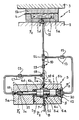
- the device comprises: - A hydraulic distributor composed of a body and a sliding drawer in said bore, this drawer comprising two heads arranged in tandem which engage in the large diameter part of the stepped bore and which are integral with a tail threaded into the small diameter portion of said stepped bore; - A pipe joining the pocket formed between the two elements of a shoe and a source of pressurized fluid via a groove dug in the large diameter bore of the distributor bore; - a control piloting pipe joining a point of the pipe and the space of the distributor located beyond the outermost head of the drawer; - a feedback control pipe joining the space of the distributor bore located beyond the end of the tail at another point of the pipe located near the distributor; - and a fitting with adjustable laminar orifice inserted in the pipe between the connection points of the two pilo pipes floor.
- the pad 1 is made in two parts, one fixed 1 has associated with the member 2 and the other 1 b secured to the member 3.
- a pocket 1 c suitably supplied with a pressurized fluid such as oil, so that between the faces facing the parts 1 a and 1 b establishes an oil film a few tens of microns thick and which has been referenced 4.
- the supply of pressurized fluid comes from a distributor 5 whose body 5 a is hollowed out with a bore with two diameters 5 b , 5 c .
- this bore can slide a drawer 6 having two tandem heads 6 a , 6 b joined by a pin 6 c , the internal head 6 b being associated with a tail 6 d engaged in the small diameter part 5 c of the bore of body 5 a of distributor 5.
- a groove 5 d has been formed from which two pipes 5 e , 5 f leave, leaving the outside of the distributor.
- the outlet of the conduit 5 f receives a connector 7 which is associated with the end of a pipe 8 coming from a source of fluid under pressure at the pressure P2.
- the outlet of the conduit 5 e receives a fitting 9 fixed to one end of a pipe 10, the other end of which is connected to a fitting 11 mounted at the outlet of a channel 1 d of the part 1 a of the shoe 1 ending in pocket 1 tsp .
- the fluid coming from the pipe 8 arrives in the pocket 1 c by a power circuit 8-5-10.
- the large-diameter part 5 b of the distributor 5 is closed by a connector 12 to which a control piloting pipe 13 is connected leading to a tee fitting 14 inserted at a point in the pipe 10. In this pipe is inserted a fitting 15 with reduced passage.
- the small diameter portion 5c of the bore of the distributor 5 comprises a connector 16 associated with one of the ends of a feedback control pipe 17, the opposite end of which leads to a tee fitting 18 inserted in a point in the pipe 10 adjacent to the distributor 5.
- a fitting 19 with an adjustable laminar orifice is inserted in the pipe 10, that is to say upstream of the connection of the pipe 13.
- a another reduced passage fitting 15 is inserted into the pipe 17.
- the width of the groove 5 d is such that if the head 6 has the outermost of the drawer 6 abuts against the connector 12, the head 6 b is still in this groove.
- the pressure P1 prevailing at the origin of the pipe 10, that is to say at the connection 9, becomes greater than that which reigned there previously, so that a flow rate is established in the feedback control pipe 17, so that the pressure P′1 prevailing in space 21 located between the end of the tail 6 d and the connector 16 increases and causes a displacement of the drawer 6 to the right until a different equilibrium position from the original after the film 4 has regained the thickness it previously had.
- This thickness only depends on the ratio P0 P1 , so that it is independent of the load and the temperature.
- the modification of the dimension of the laminar orifice of the connector 19 makes it possible to adjust the thickness of the oil film 4 to the desired value.
Landscapes
- Engineering & Computer Science (AREA)
- General Engineering & Computer Science (AREA)
- Mechanical Engineering (AREA)
- Magnetic Bearings And Hydrostatic Bearings (AREA)
- Fluid-Pressure Circuits (AREA)
Applications Claiming Priority (2)
| Application Number | Priority Date | Filing Date | Title |
|---|---|---|---|
| FR8905081 | 1989-04-12 | ||
| FR8905081A FR2645925B1 (fr) | 1989-04-12 | 1989-04-12 | Dispositif d'equilibrage de la charge d'une butee hydrostatique |
Publications (1)
| Publication Number | Publication Date |
|---|---|
| EP0392946A1 true EP0392946A1 (de) | 1990-10-17 |
Family
ID=9380814
Family Applications (1)
| Application Number | Title | Priority Date | Filing Date |
|---|---|---|---|
| EP90420183A Withdrawn EP0392946A1 (de) | 1989-04-12 | 1990-04-11 | Druckausgleichsvorrichtung für ein hydrostatisches Axiallager |
Country Status (4)
| Country | Link |
|---|---|
| EP (1) | EP0392946A1 (de) |
| FR (1) | FR2645925B1 (de) |
| NO (1) | NO901552L (de) |
| PT (1) | PT93732A (de) |
Cited By (1)
| Publication number | Priority date | Publication date | Assignee | Title |
|---|---|---|---|---|
| DE19645535A1 (de) * | 1996-11-05 | 1998-05-14 | Robert Schoenfeld | Regler zur Regelung eines mindestens einer Hydrostatik- oder Aerostatiktasche einer Lagerung, Gewindespindelmutter, oder einer Führung zugeführten Medienstromes |
Citations (1)
| Publication number | Priority date | Publication date | Assignee | Title |
|---|---|---|---|---|
| US3062593A (en) * | 1959-04-02 | 1962-11-06 | Nat Res Dev | Hydrostatic bearing |
-
1989
- 1989-04-12 FR FR8905081A patent/FR2645925B1/fr not_active Expired - Fee Related
-
1990
- 1990-04-05 NO NO90901552A patent/NO901552L/no unknown
- 1990-04-11 PT PT93732A patent/PT93732A/pt not_active Application Discontinuation
- 1990-04-11 EP EP90420183A patent/EP0392946A1/de not_active Withdrawn
Patent Citations (1)
| Publication number | Priority date | Publication date | Assignee | Title |
|---|---|---|---|---|
| US3062593A (en) * | 1959-04-02 | 1962-11-06 | Nat Res Dev | Hydrostatic bearing |
Non-Patent Citations (1)
| Title |
|---|
| ENGINEERS DIGEST, vol. 30, no. 4, avril 1969, pages 49-53,55,57, Londres, GB; J.P. O'DONOGHUE et al.: "Compensation methods for externally pressurized bearings" * |
Cited By (4)
| Publication number | Priority date | Publication date | Assignee | Title |
|---|---|---|---|---|
| DE19645535A1 (de) * | 1996-11-05 | 1998-05-14 | Robert Schoenfeld | Regler zur Regelung eines mindestens einer Hydrostatik- oder Aerostatiktasche einer Lagerung, Gewindespindelmutter, oder einer Führung zugeführten Medienstromes |
| DE19645535C2 (de) * | 1996-11-05 | 1999-02-25 | Robert Schoenfeld | Regler zur Regelung eines mindestens einer Hydrostatik- oder Aerostatiktasche einer Lagerung, Gewindespindelmutter, oder einer Führung zugeführten Medienstromes |
| US6076548A (en) * | 1996-11-05 | 2000-06-20 | Schoenfeld; Robert | Regulator for use with apparatus having a hydrostatic or aerostatic pocket |
| US6220281B1 (en) | 1996-11-05 | 2001-04-24 | Schoenfeld Robert | Regulator for use with apparatus having a hydrostatic or aerostatic pocket |
Also Published As
| Publication number | Publication date |
|---|---|
| NO901552L (no) | 1990-10-15 |
| NO901552D0 (no) | 1990-04-05 |
| PT93732A (pt) | 1992-02-28 |
| FR2645925B1 (fr) | 1991-06-21 |
| FR2645925A1 (fr) | 1990-10-19 |
Similar Documents
| Publication | Publication Date | Title |
|---|---|---|
| FR2493424A1 (fr) | Dispositif pour produire une pression de commande dependant d'une vitesse de rotation | |
| EP1883736B1 (de) | Vorrichtung zur zuführung von öl zu einem auf einer trägervorrichtung angebrachten werkzeug und hydraulische verbindungsanordnung | |
| EP0969239B1 (de) | Abschaltgerät für unter Druck stehende Flüssigkeitshandhabungs-Anlage | |
| WO1997002207A1 (fr) | Bec de remplissage a ecoulement laminaire | |
| FR2817017A1 (fr) | Refroidissement integral des injecteurs de decollage d'une chambre de combustion a deux tetes | |
| FR2646464A1 (fr) | Procede et ensemble de commande d'un appareil de forage de roches | |
| FR2781032A1 (fr) | Dispositif de regulation du debit d'eau avec moyen de decharge de pression | |
| EP0328472B1 (de) | Anlasser-Verbindungsstück für die stufenlose Druckzufuhr in pneumatischen Anlagen | |
| EP0392946A1 (de) | Druckausgleichsvorrichtung für ein hydrostatisches Axiallager | |
| BE1009338A3 (fr) | Vanne-pilote hydraulique. | |
| WO1998022693A1 (fr) | Dispositif de forage | |
| EP0176431B1 (de) | Zwei-Stufen-Druckregelungsvorrichtung | |
| FR2482018A1 (fr) | Installation pneumatique de mise de niveau par chambres de pression pour vehicules | |
| EP0029396B1 (de) | Durch ein zusammendrückbares Verschlussteil betätigtes Ventil | |
| FR2487091A1 (fr) | Dispositif de commande electro-hydraulique | |
| EP1548287B1 (de) | Positionssteuereinrichtung für eine hydraulische Stellvorrichtung und Verkettungsgrundplatte für einen Servoventil zum Betreiben einer derartigen Vorrichtung | |
| EP0613818B1 (de) | Hydraulische Spannvorrichtung für ein Aussenlastaufhängungsgerät eines Flugzeugs | |
| FR2492941A1 (fr) | Dispositif limiteur de pression differentielle a clapets | |
| FR2654350A1 (fr) | Poste a soupape d'alarme pour installations d'extinction des incendies. | |
| FR2775047A1 (fr) | Valve de passage a charge reduite d'une pompe | |
| FR2487936A1 (fr) | Dispositif de laminage fluidique | |
| FR2641583A1 (fr) | Distributeur proportionnel pour la commande de recepteurs hydrauliques | |
| FR2612084A1 (fr) | Dispositif d'injection dosee d'un adjuvant dans un debit de liquide | |
| BE468681A (de) | ||
| FR2702013A1 (fr) | Système de commande fluidique destiné à la manÓoeuvre d'un obturateur d'un corps de vanne, notamment de puits producteur d'hydrocarbures, et vanne de sécurité équipée d'un tel système de commande fluidique. |
Legal Events
| Date | Code | Title | Description |
|---|---|---|---|
| PUAI | Public reference made under article 153(3) epc to a published international application that has entered the european phase |
Free format text: ORIGINAL CODE: 0009012 |
|
| AK | Designated contracting states |
Kind code of ref document: A1 Designated state(s): AT BE CH DE DK ES FR GB GR IT LI LU NL SE |
|
| 17P | Request for examination filed |
Effective date: 19910417 |
|
| 17Q | First examination report despatched |
Effective date: 19920413 |
|
| STAA | Information on the status of an ep patent application or granted ep patent |
Free format text: STATUS: THE APPLICATION HAS BEEN WITHDRAWN |
|
| 18W | Application withdrawn |
Withdrawal date: 19920707 |
|
| ITF | It: translation for a ep patent filed |