EP1548287B1 - Positionssteuereinrichtung für eine hydraulische Stellvorrichtung und Verkettungsgrundplatte für einen Servoventil zum Betreiben einer derartigen Vorrichtung - Google Patents
Positionssteuereinrichtung für eine hydraulische Stellvorrichtung und Verkettungsgrundplatte für einen Servoventil zum Betreiben einer derartigen Vorrichtung Download PDFInfo
- Publication number
- EP1548287B1 EP1548287B1 EP04292928A EP04292928A EP1548287B1 EP 1548287 B1 EP1548287 B1 EP 1548287B1 EP 04292928 A EP04292928 A EP 04292928A EP 04292928 A EP04292928 A EP 04292928A EP 1548287 B1 EP1548287 B1 EP 1548287B1
- Authority
- EP
- European Patent Office
- Prior art keywords
- servovalve
- actuator
- hydraulic
- circuit
- control device
- Prior art date
- Legal status (The legal status is an assumption and is not a legal conclusion. Google has not performed a legal analysis and makes no representation as to the accuracy of the status listed.)
- Expired - Lifetime
Links
- 238000011144 upstream manufacturing Methods 0.000 claims abstract description 5
- 239000012530 fluid Substances 0.000 claims description 14
- 238000010586 diagram Methods 0.000 description 4
- 230000036461 convulsion Effects 0.000 description 2
- 235000021183 entrée Nutrition 0.000 description 2
- 230000005540 biological transmission Effects 0.000 description 1
- 238000006073 displacement reaction Methods 0.000 description 1
- 238000012423 maintenance Methods 0.000 description 1
- 238000004519 manufacturing process Methods 0.000 description 1
- 239000000463 material Substances 0.000 description 1
- 238000007789 sealing Methods 0.000 description 1
Images


Classifications
-
- F—MECHANICAL ENGINEERING; LIGHTING; HEATING; WEAPONS; BLASTING
- F15—FLUID-PRESSURE ACTUATORS; HYDRAULICS OR PNEUMATICS IN GENERAL
- F15B—SYSTEMS ACTING BY MEANS OF FLUIDS IN GENERAL; FLUID-PRESSURE ACTUATORS, e.g. SERVOMOTORS; DETAILS OF FLUID-PRESSURE SYSTEMS, NOT OTHERWISE PROVIDED FOR
- F15B13/00—Details of servomotor systems ; Valves for servomotor systems
- F15B13/02—Fluid distribution or supply devices characterised by their adaptation to the control of servomotors
- F15B13/06—Fluid distribution or supply devices characterised by their adaptation to the control of servomotors for use with two or more servomotors
- F15B13/08—Assemblies of units, each for the control of a single servomotor only
- F15B13/0803—Modular units
- F15B13/0807—Manifolds
-
- F—MECHANICAL ENGINEERING; LIGHTING; HEATING; WEAPONS; BLASTING
- F15—FLUID-PRESSURE ACTUATORS; HYDRAULICS OR PNEUMATICS IN GENERAL
- F15B—SYSTEMS ACTING BY MEANS OF FLUIDS IN GENERAL; FLUID-PRESSURE ACTUATORS, e.g. SERVOMOTORS; DETAILS OF FLUID-PRESSURE SYSTEMS, NOT OTHERWISE PROVIDED FOR
- F15B11/00—Servomotor systems without provision for follow-up action; Circuits therefor
- F15B11/003—Systems with load-holding valves
-
- F—MECHANICAL ENGINEERING; LIGHTING; HEATING; WEAPONS; BLASTING
- F15—FLUID-PRESSURE ACTUATORS; HYDRAULICS OR PNEUMATICS IN GENERAL
- F15B—SYSTEMS ACTING BY MEANS OF FLUIDS IN GENERAL; FLUID-PRESSURE ACTUATORS, e.g. SERVOMOTORS; DETAILS OF FLUID-PRESSURE SYSTEMS, NOT OTHERWISE PROVIDED FOR
- F15B2211/00—Circuits for servomotor systems
- F15B2211/20—Fluid pressure source, e.g. accumulator or variable axial piston pump
- F15B2211/205—Systems with pumps
- F15B2211/2053—Type of pump
- F15B2211/20546—Type of pump variable capacity
-
- F—MECHANICAL ENGINEERING; LIGHTING; HEATING; WEAPONS; BLASTING
- F15—FLUID-PRESSURE ACTUATORS; HYDRAULICS OR PNEUMATICS IN GENERAL
- F15B—SYSTEMS ACTING BY MEANS OF FLUIDS IN GENERAL; FLUID-PRESSURE ACTUATORS, e.g. SERVOMOTORS; DETAILS OF FLUID-PRESSURE SYSTEMS, NOT OTHERWISE PROVIDED FOR
- F15B2211/00—Circuits for servomotor systems
- F15B2211/30—Directional control
- F15B2211/305—Directional control characterised by the type of valves
- F15B2211/30505—Non-return valves, i.e. check valves
- F15B2211/3051—Cross-check valves
-
- F—MECHANICAL ENGINEERING; LIGHTING; HEATING; WEAPONS; BLASTING
- F15—FLUID-PRESSURE ACTUATORS; HYDRAULICS OR PNEUMATICS IN GENERAL
- F15B—SYSTEMS ACTING BY MEANS OF FLUIDS IN GENERAL; FLUID-PRESSURE ACTUATORS, e.g. SERVOMOTORS; DETAILS OF FLUID-PRESSURE SYSTEMS, NOT OTHERWISE PROVIDED FOR
- F15B2211/00—Circuits for servomotor systems
- F15B2211/30—Directional control
- F15B2211/305—Directional control characterised by the type of valves
- F15B2211/30525—Directional control valves, e.g. 4/3-directional control valve
-
- F—MECHANICAL ENGINEERING; LIGHTING; HEATING; WEAPONS; BLASTING
- F15—FLUID-PRESSURE ACTUATORS; HYDRAULICS OR PNEUMATICS IN GENERAL
- F15B—SYSTEMS ACTING BY MEANS OF FLUIDS IN GENERAL; FLUID-PRESSURE ACTUATORS, e.g. SERVOMOTORS; DETAILS OF FLUID-PRESSURE SYSTEMS, NOT OTHERWISE PROVIDED FOR
- F15B2211/00—Circuits for servomotor systems
- F15B2211/30—Directional control
- F15B2211/31—Directional control characterised by the positions of the valve element
- F15B2211/3105—Neutral or centre positions
- F15B2211/3111—Neutral or centre positions the pump port being closed in the centre position, e.g. so-called closed centre
-
- F—MECHANICAL ENGINEERING; LIGHTING; HEATING; WEAPONS; BLASTING
- F15—FLUID-PRESSURE ACTUATORS; HYDRAULICS OR PNEUMATICS IN GENERAL
- F15B—SYSTEMS ACTING BY MEANS OF FLUIDS IN GENERAL; FLUID-PRESSURE ACTUATORS, e.g. SERVOMOTORS; DETAILS OF FLUID-PRESSURE SYSTEMS, NOT OTHERWISE PROVIDED FOR
- F15B2211/00—Circuits for servomotor systems
- F15B2211/30—Directional control
- F15B2211/31—Directional control characterised by the positions of the valve element
- F15B2211/3144—Directional control characterised by the positions of the valve element the positions being continuously variable, e.g. as realised by proportional valves
-
- F—MECHANICAL ENGINEERING; LIGHTING; HEATING; WEAPONS; BLASTING
- F15—FLUID-PRESSURE ACTUATORS; HYDRAULICS OR PNEUMATICS IN GENERAL
- F15B—SYSTEMS ACTING BY MEANS OF FLUIDS IN GENERAL; FLUID-PRESSURE ACTUATORS, e.g. SERVOMOTORS; DETAILS OF FLUID-PRESSURE SYSTEMS, NOT OTHERWISE PROVIDED FOR
- F15B2211/00—Circuits for servomotor systems
- F15B2211/30—Directional control
- F15B2211/315—Directional control characterised by the connections of the valve or valves in the circuit
- F15B2211/3157—Directional control characterised by the connections of the valve or valves in the circuit being connected to a pressure source, an output member and a return line
- F15B2211/31576—Directional control characterised by the connections of the valve or valves in the circuit being connected to a pressure source, an output member and a return line having a single pressure source and a single output member
-
- F—MECHANICAL ENGINEERING; LIGHTING; HEATING; WEAPONS; BLASTING
- F15—FLUID-PRESSURE ACTUATORS; HYDRAULICS OR PNEUMATICS IN GENERAL
- F15B—SYSTEMS ACTING BY MEANS OF FLUIDS IN GENERAL; FLUID-PRESSURE ACTUATORS, e.g. SERVOMOTORS; DETAILS OF FLUID-PRESSURE SYSTEMS, NOT OTHERWISE PROVIDED FOR
- F15B2211/00—Circuits for servomotor systems
- F15B2211/30—Directional control
- F15B2211/32—Directional control characterised by the type of actuation
- F15B2211/327—Directional control characterised by the type of actuation electrically or electronically
-
- F—MECHANICAL ENGINEERING; LIGHTING; HEATING; WEAPONS; BLASTING
- F15—FLUID-PRESSURE ACTUATORS; HYDRAULICS OR PNEUMATICS IN GENERAL
- F15B—SYSTEMS ACTING BY MEANS OF FLUIDS IN GENERAL; FLUID-PRESSURE ACTUATORS, e.g. SERVOMOTORS; DETAILS OF FLUID-PRESSURE SYSTEMS, NOT OTHERWISE PROVIDED FOR
- F15B2211/00—Circuits for servomotor systems
- F15B2211/30—Directional control
- F15B2211/32—Directional control characterised by the type of actuation
- F15B2211/329—Directional control characterised by the type of actuation actuated by fluid pressure
-
- F—MECHANICAL ENGINEERING; LIGHTING; HEATING; WEAPONS; BLASTING
- F15—FLUID-PRESSURE ACTUATORS; HYDRAULICS OR PNEUMATICS IN GENERAL
- F15B—SYSTEMS ACTING BY MEANS OF FLUIDS IN GENERAL; FLUID-PRESSURE ACTUATORS, e.g. SERVOMOTORS; DETAILS OF FLUID-PRESSURE SYSTEMS, NOT OTHERWISE PROVIDED FOR
- F15B2211/00—Circuits for servomotor systems
- F15B2211/40—Flow control
- F15B2211/405—Flow control characterised by the type of flow control means or valve
- F15B2211/40507—Flow control characterised by the type of flow control means or valve with constant throttles or orifices
-
- F—MECHANICAL ENGINEERING; LIGHTING; HEATING; WEAPONS; BLASTING
- F15—FLUID-PRESSURE ACTUATORS; HYDRAULICS OR PNEUMATICS IN GENERAL
- F15B—SYSTEMS ACTING BY MEANS OF FLUIDS IN GENERAL; FLUID-PRESSURE ACTUATORS, e.g. SERVOMOTORS; DETAILS OF FLUID-PRESSURE SYSTEMS, NOT OTHERWISE PROVIDED FOR
- F15B2211/00—Circuits for servomotor systems
- F15B2211/40—Flow control
- F15B2211/415—Flow control characterised by the connections of the flow control means in the circuit
- F15B2211/41581—Flow control characterised by the connections of the flow control means in the circuit being connected to an output member and a return line
-
- F—MECHANICAL ENGINEERING; LIGHTING; HEATING; WEAPONS; BLASTING
- F15—FLUID-PRESSURE ACTUATORS; HYDRAULICS OR PNEUMATICS IN GENERAL
- F15B—SYSTEMS ACTING BY MEANS OF FLUIDS IN GENERAL; FLUID-PRESSURE ACTUATORS, e.g. SERVOMOTORS; DETAILS OF FLUID-PRESSURE SYSTEMS, NOT OTHERWISE PROVIDED FOR
- F15B2211/00—Circuits for servomotor systems
- F15B2211/40—Flow control
- F15B2211/46—Control of flow in the return line, i.e. meter-out control
-
- F—MECHANICAL ENGINEERING; LIGHTING; HEATING; WEAPONS; BLASTING
- F15—FLUID-PRESSURE ACTUATORS; HYDRAULICS OR PNEUMATICS IN GENERAL
- F15B—SYSTEMS ACTING BY MEANS OF FLUIDS IN GENERAL; FLUID-PRESSURE ACTUATORS, e.g. SERVOMOTORS; DETAILS OF FLUID-PRESSURE SYSTEMS, NOT OTHERWISE PROVIDED FOR
- F15B2211/00—Circuits for servomotor systems
- F15B2211/70—Output members, e.g. hydraulic motors or cylinders or control therefor
- F15B2211/705—Output members, e.g. hydraulic motors or cylinders or control therefor characterised by the type of output members or actuators
- F15B2211/7051—Linear output members
- F15B2211/7053—Double-acting output members
-
- F—MECHANICAL ENGINEERING; LIGHTING; HEATING; WEAPONS; BLASTING
- F15—FLUID-PRESSURE ACTUATORS; HYDRAULICS OR PNEUMATICS IN GENERAL
- F15B—SYSTEMS ACTING BY MEANS OF FLUIDS IN GENERAL; FLUID-PRESSURE ACTUATORS, e.g. SERVOMOTORS; DETAILS OF FLUID-PRESSURE SYSTEMS, NOT OTHERWISE PROVIDED FOR
- F15B2211/00—Circuits for servomotor systems
- F15B2211/70—Output members, e.g. hydraulic motors or cylinders or control therefor
- F15B2211/75—Control of speed of the output member
-
- F—MECHANICAL ENGINEERING; LIGHTING; HEATING; WEAPONS; BLASTING
- F15—FLUID-PRESSURE ACTUATORS; HYDRAULICS OR PNEUMATICS IN GENERAL
- F15B—SYSTEMS ACTING BY MEANS OF FLUIDS IN GENERAL; FLUID-PRESSURE ACTUATORS, e.g. SERVOMOTORS; DETAILS OF FLUID-PRESSURE SYSTEMS, NOT OTHERWISE PROVIDED FOR
- F15B2211/00—Circuits for servomotor systems
- F15B2211/70—Output members, e.g. hydraulic motors or cylinders or control therefor
- F15B2211/765—Control of position or angle of the output member
-
- F—MECHANICAL ENGINEERING; LIGHTING; HEATING; WEAPONS; BLASTING
- F15—FLUID-PRESSURE ACTUATORS; HYDRAULICS OR PNEUMATICS IN GENERAL
- F15B—SYSTEMS ACTING BY MEANS OF FLUIDS IN GENERAL; FLUID-PRESSURE ACTUATORS, e.g. SERVOMOTORS; DETAILS OF FLUID-PRESSURE SYSTEMS, NOT OTHERWISE PROVIDED FOR
- F15B2211/00—Circuits for servomotor systems
- F15B2211/80—Other types of control related to particular problems or conditions
- F15B2211/88—Control measures for saving energy
Definitions
- the technical field of the invention is that of devices for controlling in position a hydraulic actuator.
- These devices usually comprise a hydraulic circuit incorporating a pump (for example variable displacement) which feeds one or the other of the two chambers of the actuator via a servovalve.
- a pump for example variable displacement
- Such a device comprises a hydraulic circuit comprising a pump feeding from a cover the two chambers of the actuator via a servovalve.
- Each channel of the servo valve is connected to a chamber of the actuator via a check valve and the output channels of the servo valve are also connected to the tank by a calibrated nozzle.
- the US-3763889 discloses a hydraulic distribution system comprising a set of three plates welded together and providing an interface plate for applying to one or more multi-way directional valves. This patent discloses neither a reserve cover outlet nor a leakage circuit.
- the servovalve is a standard commercial component that includes a movable drawer by the action of a torque motor.
- This drawer can occupy at least three different positions: a central position in which the circuits are closed and two symmetrical positions for connecting one or the other of the chambers of the actuator to the hydraulic pump while the other chamber is connected to a sheet or hydraulic reserve.
- the slide can also occupy, depending on the command given by the torque motor, any intermediate position between the central position and one or the other of the extreme positions, each intermediate position corresponding to a different fluid flow rate delivered by the servovalve.
- Such a servovalve is used in a conventional manner in closed-loop actuator controls, ie controls with position control. It is also possible to use such a servo valve for open loop actuator control, ie without position control.
- the actuator is a cylinder ensuring the pointing of a weapon in site
- the rally angle obtained site is wrong compared to the given instruction and the weapon is poorly pointed.
- the object of the invention is to overcome such drawbacks by proposing a control device in the position of a hydraulic actuator enabling control both in closed loop in open loop while ensuring the accuracy of positioning and speed of rallying.
- the invention also makes it possible to ensure this positioning with standard components of commerce and inexpensive.
- the subject of the invention is a control device in the position of a hydraulic actuator, the device comprising a hydraulic circuit comprising a pump supplying the two chambers of the actuator via a cover or hydraulic reserve via a servovalve, each output channel of the servovalve being connected to a chamber of the actuator via a check valve, at least one of the output channels of the servovalve which is connected to a chamber of the actuator being also connected to the hydraulic cover by a calibrated nozzle upstream of the non-return valve, characterized in that the device further comprises a servovalve interface plate comprising at least four transverse holes intended cooperating with the four openings or hydraulic connections (A, B, P, T) of the servovalve, that is to say a supply of fluid under pressure from a pump, an outlet to a reserve tank, a first control channel of a first chamber of the actuator and a second control channel of a second chamber of the actuator, said plate comprising at least one leakage circuit connecting one of the control channels to the
- the plate comprises two leakage circuits comprising a calibrated nozzle, each circuit connecting one of the control channels to the tarpaulin outlet.
- the leakage circuit or circuits are made in the form of holes perpendicular to each other and perpendicular to the transverse bores corresponding to the different channels.
- the outlet of each hole outside the plate is closed by a plug.
- the nozzle or jets are made in the form of screws comprising a calibrated axial orifice.
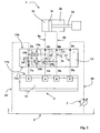
- the figure 1 represents the diagram of a device 1 for controlling the position of a hydraulic actuator 2, for example a jack comprising a piston 2c integral with a rod 2d and delimiting two chambers 2a and 2b.
- the cylinder ensures the positioning in site or in the field of a weapon tube (not shown).
- This device comprises a hydraulic circuit incorporating a pump 3 which feeds the two chambers 2a, 2b of the actuator 2 via a servovalve 4.
- connection T is intended for the return to the cover 5, the input connection P to the supply of fluid from the pump 3, the connections of output A and B being intended to connect the servovalve 4 to the two chambers 2a and 2b of the cylinder 2.
- the pump 3 is thus connected by an upstream pipe 6a to the hydraulic tank 5 (or reserve of fluid) and it flows through a downstream pipe 6b to the inlet connection P of the servovalve 4.
- the servovalve 4 is conventionally represented on the figure 1 in its closed position (central block 4c in the circuit) in which the four connections A, B, P and T are closed.
- the movements of the servovalve spool are controlled conventionally by a torque motor 4d integrated into the servovalve, a torque motor which is controlled by an electronic control unit 7.
- the extreme positions 4a, 4b correspond to the maximum fluid flow rates provided by the servovalve.
- the drawer can conventionally occupy intermediate positions between the closed position and one or the other of the two extreme positions. These intermediate positions correspond to different fluid flows transmitted according to one or other of the control channels.
- the output connections A and B of the servovalve 4 are connected by ducts 8a and 8b to the chambers 2a and 2b of the cylinder 2 via two controlled check valves 9a, 9b.
- valves are represented here in the form of a single hydraulic block 9 having four outputs C, D, E and F.
- Each valve 9a, 9b comprises a ball applied to a seat by the pressure on the side of the actuator 2 The ball can be moved away from the seat by a control pressure.
- the valve 9a is interposed between the outputs C and E and connects the chamber 2a of the actuator and the connection A of the servovalve 4.
- the valve 9b is interposed between the outputs D and F and connects the chamber 2b of the actuator and the connection B of the servovalve 4. Hydraulic connections 9c and 9d (shown in dashed lines) provide the control of the valves 9b and 9a respectively.
- a pressure inlet D flows naturally towards F through the valve 9b and also raises the ball of the valve 9a thereby allowing a fluid passage from E to C.
- a pressure inlet C flows to E and allows a fluid passage from F to D.
- valves 9a and 9b make it possible to hold the jack 2 in position when it is controlled in an open loop or in a closed loop.
- a first nozzle 10a is connected by a pipe 11a to the pipe 8a and it drifts towards the tank 5 a portion of the fluid flowing therein.
- a second nozzle 10b is connected by a pipe 11b to the pipe 8b and it drifts towards the tank 5 a portion of the fluid flowing in it.
- the nozzles will consist of well defined nozzle sizes.
- the gauges will be chosen so as to ensure a pressure drop in line 8a or 8b which is inactive without reducing the flow in the pipe 8b or 8a which controls the movement.
- leakage sections will be chosen for the nozzles which will make it possible to ensure a leakage rate of between 4% and 7% of the flow rate of fluid supplied by the pump 3.
- the nozzles 10a and 10b do not therefore disturb the normal operation of the servovalve 4 because they do not cause significant loss of flow in a pipe fed by the pump 3.
- the pressure in the lines 8a and 8b at the inputs C and D is lower than that which is respectively at the inputs E and F.
- the balls therefore remain applied on their seats and avoids any rebound which would lead to a jerk positioning of the cylinder.
- the pointing is thus obtained with precision during positioning servo positioning of the closed-loop cylinder and the position is maintained without drift during an open-loop servocontrol.
- the figure 2 shows a simplified hydraulic diagram of the interface plate 13 and the figures 3a , 3b and 3c show a particular embodiment of this interface plate.
- a servovalve 4 is concretely made in the form of a component comprising a parallelepipedal base 12 which carries on the same upper face 12a the openings (or connections) of inputs and outputs A, B, T and P.
- the interface plate 13 is also made in the form of a parallelepiped block, a lower face 13a is intended to be applied to the face 12a of the servovalve.
- This face comprises four openings Ta, Aa, Ba and Pa intended to be facing respective openings T, A, B and P of the servovalve 4.
- each opening (Ta, Aa, Ba , Pa) of the interface plate 13 comprises a counterbore which accommodates an O-ring. This seal will be applied during assembly against the face 12a of the servovalve and will seal.
- An upper face 13b of the plate 13 carries four openings Tb, Ab, Bb and Pb on which will be connected the different pipes of the hydraulic circuit.
- the pipes 8a and 8b which lead to the jack are fixed to the openings Ab and Bb, the pipe 6b which comes from the pump 3 is fixed to the opening Pb and the pipe 18 which returns to the hydraulic tank 5 is fixed to the opening Tb.
- Fasteners are made with appropriate hydraulic connections.
- the different openings of the lower face 13a are connected to the openings of the upper face 13b by bores machined in the material of the plate 13.
- the opening Ta is connected to the opening Tb by the bore 14
- the opening Aa is connected to the opening Ab by the bore 15
- the opening Ba is connected to the opening Bb by the bore 16
- the opening Pa is connected to opening Pb by piercing 17.
- a first controlled hydraulic leakage circuit 19a is formed by a channel on which is disposed the nozzle 10a, and which connects the bore 15 and the bore 14.
- the plate also contains a second leakage circuit 19b formed by another channel on which is disposed the nozzle 10b. This second leakage circuit 19b connects the piercing 16 and the piercing 14.
- the plate 13 makes it possible to convert the servovalve 4 in an extremely simple manner to add the nozzles proposed by the invention.
- the hydraulic circuit can therefore easily be modified without the need for additional pipes.
- the leakage circuits 19a and 19b are in the form of orthogonal holes. Such an arrangement makes it easier to manufacture the interface plate 13.
- the holes are made in two parallel planes.
- the AA plan ( figure 3a ) comprises two orthogonal holes 19a1 and 19a2 which form the first leak circuit 19a.
- the hole 19a2 contains the first nozzle 10a which is in the form of a screw having a calibrated axial orifice.
- the plan BB ( figure 3b ) comprises four holes 19b1, 19b2, 19b3 and 19b4 which are orthogonal two by two and thus form a rectangle. These four holes constitute the second leakage circuit 19b.
- the hole 19b1 contains the second nozzle 10b which is also made in the form of a screw with a calibrated axial orifice.
- Holes 21 passing through the interface plate 13 from one side to the other are provided to allow the plate to be fixed to the servovalve 4 by screws (not shown).
- This variant makes it possible to accelerate in a preferential manner one of the movements of the jack.
Landscapes
- Engineering & Computer Science (AREA)
- Physics & Mathematics (AREA)
- Fluid Mechanics (AREA)
- Mechanical Engineering (AREA)
- General Engineering & Computer Science (AREA)
- Fluid-Pressure Circuits (AREA)
- Servomotors (AREA)
Claims (5)
- Positionssteuerungsvorrichtung (1) eines hydraulischen Stellgliedes (2), wobei die Vorrichtung einen Hydraulikkreis umfasst, der eine Pumpe (3) umfasst, die ausgehend von einem hydraulischen Sammelbehälter oder Tank (5) die beiden Kammern (2a, 2b) des Stellgliedes mit Hilfe eines Servoventils (4) versorgt, wobei jeder Austrittsweg des Servoventils mit einer Kammer des Stellgliedes mit Hilfe eines Rückschlagventils (9a, 9b) verbunden ist, wobei wenigstens einer der Austrittswege (8a, 8b) des Servoventils, der an eine Kammer (2a, 2b) des Stellgliedes angeschlossen ist, ebenfalls mit dem hydraulischen Sammelbehälter (5) durch eine stromaufwärts des Rückschlagventils (9a, 9b) gelegene kalibrierte Düse (10a, 10b) verbunden ist, dadurch gekennzeichnet, dass die Vorrichtung außerdem eine Servoventil-Stirnflächenplatte (13) umfasst, umfassend wenigstens vier Querbohrungen (14, 15, 16, 17), die mit den vier hydraulischen Öffnungen oder Verbindungen (A, B, P, T) des Servoventils zusammenwirken, das bedeutet also eine Versorgung mit unter Druck stehendem Fluid ausgehend von einer Pumpe (3), einen Austritt zum Sammelbehälter (5), einen ersten Weg zur Steuerung (8a) einer ersten Kammer (2a) des Stellgliedes und einen zweiten Weg zur Steuerung (8b) einer zweiten Kammer (2b) des Stellgliedes, wobei die genannte Platte wenigstens einen Leckkreis (19a, 19b) umfasst, der einen der Steuerungswege mit dem Austritt Sammelbehälter (5) verbindet, wobei in dem Kreis die genannte kalibrierte Düse (10a, 10b) angeordnet ist.
- Steuerungsvorrichtung (1) nach Anspruch 1, dadurch gekennzeichnet, dass die Platte zwei Leckkreise (19a, 19b) umfasst, die eine kalibrierte Düse (10a, 10b) aufweisen, wobei jeder Kreis eine der Steuerungswege mit dem Austritt Sammelbehälter (5) verbindet.
- Steuerungsvorrichtung (1) nach einem der Ansprüche 1 oder 2, dadurch gekennzeichnet, dass der oder die Leckkreise in der Form von Löchern (19a1, 19a2, 19b1, 19b2, 19b3, 19b4) ausgeführt sind, die senkrecht zueinander und senkrecht zu den Querbohrungen (14, 15, 16) sind, die den verschiedenen Wegen entsprechen.
- Steuerungsvorrichtung (1) nach Anspruch 3, dadurch gekennzeichnet, dass die Öffnung von jedem Loch nach außen von der Platte von einem Stopfen (20) verschlossen wird.
- Steuerungsvorrichtung (1) nach einem der vorhergehenden Ansprüche, dadurch gekennzeichnet, dass die Düse oder Düsen (10a, 10b) in der Form einer Schraube ausgeführt sind, die eine kalibrierte, axiale Öffnung umfasst.
Priority Applications (1)
| Application Number | Priority Date | Filing Date | Title |
|---|---|---|---|
| PL04292928T PL1548287T3 (pl) | 2003-12-23 | 2004-12-09 | Urządzenie do sterowania położeniowego hydraulicznym mechanizmem wykonawczym i płyta sprzęgająca dla serwozaworu wykorzystującego takie urządzenie |
Applications Claiming Priority (2)
| Application Number | Priority Date | Filing Date | Title |
|---|---|---|---|
| FR0315427 | 2003-12-23 | ||
| FR0315427A FR2864178B1 (fr) | 2003-12-23 | 2003-12-23 | Dispositif de commande en position d'un actionneur hydraulique et plaque interface de servovalve mettant en oeuvre un tel dispositif |
Publications (2)
| Publication Number | Publication Date |
|---|---|
| EP1548287A1 EP1548287A1 (de) | 2005-06-29 |
| EP1548287B1 true EP1548287B1 (de) | 2009-04-08 |
Family
ID=34531358
Family Applications (1)
| Application Number | Title | Priority Date | Filing Date |
|---|---|---|---|
| EP04292928A Expired - Lifetime EP1548287B1 (de) | 2003-12-23 | 2004-12-09 | Positionssteuereinrichtung für eine hydraulische Stellvorrichtung und Verkettungsgrundplatte für einen Servoventil zum Betreiben einer derartigen Vorrichtung |
Country Status (7)
| Country | Link |
|---|---|
| US (1) | US20050132876A1 (de) |
| EP (1) | EP1548287B1 (de) |
| AT (1) | ATE428056T1 (de) |
| DE (1) | DE602004020440D1 (de) |
| ES (1) | ES2325395T3 (de) |
| FR (1) | FR2864178B1 (de) |
| PL (1) | PL1548287T3 (de) |
Families Citing this family (3)
| Publication number | Priority date | Publication date | Assignee | Title |
|---|---|---|---|---|
| US20100096576A1 (en) * | 2008-10-22 | 2010-04-22 | Mark Sommer | Valve bleed system |
| EP2454490B1 (de) * | 2009-07-16 | 2013-05-01 | Schaeffler Technologies AG & Co. KG | Hydrauliksystem |
| US11274752B2 (en) * | 2020-01-08 | 2022-03-15 | Sun Hydraulics, Llc | Flow control valve with load-sense signal generation |
Family Cites Families (8)
| Publication number | Priority date | Publication date | Assignee | Title |
|---|---|---|---|---|
| US2672731A (en) * | 1951-08-01 | 1954-03-23 | Electrol Inc | Self-contained power actuator |
| US3184920A (en) * | 1963-06-12 | 1965-05-25 | Caterpillar Tractor Co | Leakage control for bulldozer pitch jack circuit |
| US3543647A (en) * | 1969-05-02 | 1970-12-01 | Deere & Co | Control valve means for a two-way hydraulic cylinder |
| US4051764A (en) * | 1975-06-05 | 1977-10-04 | Hikaru Murata | Hydraulic actuating system |
| FR2321416A1 (fr) * | 1975-08-21 | 1977-03-18 | Dba | Dispositif hydraulique d'assistance pour direction de vehicule automobile |
| FR2360801A1 (fr) * | 1976-04-30 | 1978-03-03 | Ppm Sa | Dispositif de controle de la mise en communication de deux enceintes et suspension de vehicule en faisant application |
| JPS5947506A (ja) * | 1982-09-09 | 1984-03-17 | Fuji Eng Kk | 複合弁 |
| US6516706B2 (en) * | 1999-08-19 | 2003-02-11 | Delaware Capital Formation, Inc. | Actuator having internal valve structure |
-
2003
- 2003-12-23 FR FR0315427A patent/FR2864178B1/fr not_active Expired - Fee Related
-
2004
- 2004-07-23 US US10/896,931 patent/US20050132876A1/en not_active Abandoned
- 2004-12-09 EP EP04292928A patent/EP1548287B1/de not_active Expired - Lifetime
- 2004-12-09 PL PL04292928T patent/PL1548287T3/pl unknown
- 2004-12-09 DE DE602004020440T patent/DE602004020440D1/de not_active Expired - Lifetime
- 2004-12-09 AT AT04292928T patent/ATE428056T1/de not_active IP Right Cessation
- 2004-12-09 ES ES04292928T patent/ES2325395T3/es not_active Expired - Lifetime
Also Published As
| Publication number | Publication date |
|---|---|
| US20050132876A1 (en) | 2005-06-23 |
| ATE428056T1 (de) | 2009-04-15 |
| ES2325395T3 (es) | 2009-09-03 |
| FR2864178B1 (fr) | 2006-02-17 |
| DE602004020440D1 (de) | 2009-05-20 |
| EP1548287A1 (de) | 2005-06-29 |
| FR2864178A1 (fr) | 2005-06-24 |
| PL1548287T3 (pl) | 2009-09-30 |
Similar Documents
| Publication | Publication Date | Title |
|---|---|---|
| EP2037048A3 (de) | Vorrichtung zur Durchfluß-Steuerung für schwere Arbeitsausrüstung. | |
| EP2006587B1 (de) | Dichtungsventilsystem | |
| EP0915241A2 (de) | System zur Unterbrechung eines Kraftstofflusses | |
| FR2463446A1 (fr) | Commande prioritaire de pression | |
| FR2511328A1 (fr) | Direction assistee hydrostatique | |
| FR2480368A1 (fr) | Ensemble de valves de commande a sections multiples | |
| EP1548287B1 (de) | Positionssteuereinrichtung für eine hydraulische Stellvorrichtung und Verkettungsgrundplatte für einen Servoventil zum Betreiben einer derartigen Vorrichtung | |
| US7004199B1 (en) | Fluid control apparatus | |
| EP2980417B1 (de) | Servoventil mit doppeltem bewegungselement | |
| FR3027350B1 (fr) | Injecteur de carburant | |
| EP3092065A1 (de) | Vormischer und zugehörige installation | |
| WO2014095595A1 (fr) | Buse, vanne haute pression apte a recevoir la buse et rampe commune apte a recevoir la buse | |
| EP2356356B1 (de) | Ventil zum spritzen von beschichtungsmaterial und spritzpistole mit einem solchen ventil. | |
| FR2985284A1 (fr) | Dispositif pour la commande du calage des pales d'une helice | |
| FR2559595A1 (fr) | Distributeur hydraulique a compensation de pression | |
| WO1998022693A1 (fr) | Dispositif de forage | |
| FR2634817A1 (fr) | Dispositif pour commander des moyens hydrauliques d'actionnement dans une fleche de forage de roche et une structure de fleche analogue | |
| FR2492941A1 (fr) | Dispositif limiteur de pression differentielle a clapets | |
| FR2865013A1 (fr) | Robinet de garde de turbine avec by-pass integre | |
| FR2702526A1 (fr) | Dispositif d'assemblage en rotation d'un bras ou analogue avec et entre deux branches d'une pièce en forme de fourche. | |
| FR2845439A1 (fr) | Dispositif a vannes hydrauliques | |
| FR2511111A1 (fr) | Vanne de commande multiple | |
| FR2585415A1 (fr) | Unite electro-hydraulique de servocommande, notamment a tiroir de distribution de fluide de pression | |
| FR2921440A3 (fr) | Dispositif d'injection de carburant | |
| WO2019186039A1 (fr) | Vanne de regulation amelioree avec fonction de purge integree |
Legal Events
| Date | Code | Title | Description |
|---|---|---|---|
| PUAI | Public reference made under article 153(3) epc to a published international application that has entered the european phase |
Free format text: ORIGINAL CODE: 0009012 |
|
| AK | Designated contracting states |
Kind code of ref document: A1 Designated state(s): AT BE BG CH CY CZ DE DK EE ES FI FR GB GR HU IE IS IT LI LT LU MC NL PL PT RO SE SI SK TR |
|
| AX | Request for extension of the european patent |
Extension state: AL BA HR LV MK YU |
|
| 17P | Request for examination filed |
Effective date: 20051208 |
|
| AKX | Designation fees paid |
Designated state(s): AT BE BG CH CY CZ DE DK EE ES FI FR GB GR HU IE IS IT LI LT LU MC NL PL PT RO SE SI SK TR |
|
| RAP1 | Party data changed (applicant data changed or rights of an application transferred) |
Owner name: NEXTER SYSTEMS |
|
| 17Q | First examination report despatched |
Effective date: 20060214 |
|
| GRAP | Despatch of communication of intention to grant a patent |
Free format text: ORIGINAL CODE: EPIDOSNIGR1 |
|
| GRAS | Grant fee paid |
Free format text: ORIGINAL CODE: EPIDOSNIGR3 |
|
| GRAA | (expected) grant |
Free format text: ORIGINAL CODE: 0009210 |
|
| AK | Designated contracting states |
Kind code of ref document: B1 Designated state(s): AT BE BG CH CY CZ DE DK EE ES FI FR GB GR HU IE IS IT LI LT LU MC NL PL PT RO SE SI SK TR |
|
| REG | Reference to a national code |
Ref country code: GB Ref legal event code: FG4D Free format text: NOT ENGLISH |
|
| REG | Reference to a national code |
Ref country code: CH Ref legal event code: EP |
|
| REG | Reference to a national code |
Ref country code: IE Ref legal event code: FG4D |
|
| REF | Corresponds to: |
Ref document number: 602004020440 Country of ref document: DE Date of ref document: 20090520 Kind code of ref document: P |
|
| REG | Reference to a national code |
Ref country code: SE Ref legal event code: TRGR |
|
| PG25 | Lapsed in a contracting state [announced via postgrant information from national office to epo] |
Ref country code: SI Free format text: LAPSE BECAUSE OF FAILURE TO SUBMIT A TRANSLATION OF THE DESCRIPTION OR TO PAY THE FEE WITHIN THE PRESCRIBED TIME-LIMIT Effective date: 20090408 |
|
| NLV1 | Nl: lapsed or annulled due to failure to fulfill the requirements of art. 29p and 29m of the patents act | ||
| REG | Reference to a national code |
Ref country code: ES Ref legal event code: FG2A Ref document number: 2325395 Country of ref document: ES Kind code of ref document: T3 |
|
| REG | Reference to a national code |
Ref country code: PL Ref legal event code: T3 |
|
| REG | Reference to a national code |
Ref country code: IE Ref legal event code: FD4D |
|
| PG25 | Lapsed in a contracting state [announced via postgrant information from national office to epo] |
Ref country code: LT Free format text: LAPSE BECAUSE OF FAILURE TO SUBMIT A TRANSLATION OF THE DESCRIPTION OR TO PAY THE FEE WITHIN THE PRESCRIBED TIME-LIMIT Effective date: 20090408 Ref country code: PT Free format text: LAPSE BECAUSE OF FAILURE TO SUBMIT A TRANSLATION OF THE DESCRIPTION OR TO PAY THE FEE WITHIN THE PRESCRIBED TIME-LIMIT Effective date: 20090908 Ref country code: AT Free format text: LAPSE BECAUSE OF FAILURE TO SUBMIT A TRANSLATION OF THE DESCRIPTION OR TO PAY THE FEE WITHIN THE PRESCRIBED TIME-LIMIT Effective date: 20090408 |
|
| PG25 | Lapsed in a contracting state [announced via postgrant information from national office to epo] |
Ref country code: IS Free format text: LAPSE BECAUSE OF FAILURE TO SUBMIT A TRANSLATION OF THE DESCRIPTION OR TO PAY THE FEE WITHIN THE PRESCRIBED TIME-LIMIT Effective date: 20090808 Ref country code: NL Free format text: LAPSE BECAUSE OF FAILURE TO SUBMIT A TRANSLATION OF THE DESCRIPTION OR TO PAY THE FEE WITHIN THE PRESCRIBED TIME-LIMIT Effective date: 20090408 |
|
| PG25 | Lapsed in a contracting state [announced via postgrant information from national office to epo] |
Ref country code: RO Free format text: LAPSE BECAUSE OF FAILURE TO SUBMIT A TRANSLATION OF THE DESCRIPTION OR TO PAY THE FEE WITHIN THE PRESCRIBED TIME-LIMIT Effective date: 20090408 Ref country code: DK Free format text: LAPSE BECAUSE OF FAILURE TO SUBMIT A TRANSLATION OF THE DESCRIPTION OR TO PAY THE FEE WITHIN THE PRESCRIBED TIME-LIMIT Effective date: 20090408 Ref country code: EE Free format text: LAPSE BECAUSE OF FAILURE TO SUBMIT A TRANSLATION OF THE DESCRIPTION OR TO PAY THE FEE WITHIN THE PRESCRIBED TIME-LIMIT Effective date: 20090408 Ref country code: IE Free format text: LAPSE BECAUSE OF FAILURE TO SUBMIT A TRANSLATION OF THE DESCRIPTION OR TO PAY THE FEE WITHIN THE PRESCRIBED TIME-LIMIT Effective date: 20090408 |
|
| PGFP | Annual fee paid to national office [announced via postgrant information from national office to epo] |
Ref country code: CZ Payment date: 20091125 Year of fee payment: 6 |
|
| PLBE | No opposition filed within time limit |
Free format text: ORIGINAL CODE: 0009261 |
|
| STAA | Information on the status of an ep patent application or granted ep patent |
Free format text: STATUS: NO OPPOSITION FILED WITHIN TIME LIMIT |
|
| PGFP | Annual fee paid to national office [announced via postgrant information from national office to epo] |
Ref country code: SK Payment date: 20091130 Year of fee payment: 6 |
|
| 26N | No opposition filed |
Effective date: 20100111 |
|
| PG25 | Lapsed in a contracting state [announced via postgrant information from national office to epo] |
Ref country code: BG Free format text: LAPSE BECAUSE OF FAILURE TO SUBMIT A TRANSLATION OF THE DESCRIPTION OR TO PAY THE FEE WITHIN THE PRESCRIBED TIME-LIMIT Effective date: 20090708 |
|
| BERE | Be: lapsed |
Owner name: NEXTER SYSTEMS Effective date: 20091231 |
|
| PG25 | Lapsed in a contracting state [announced via postgrant information from national office to epo] |
Ref country code: MC Free format text: LAPSE BECAUSE OF NON-PAYMENT OF DUE FEES Effective date: 20100701 |
|
| REG | Reference to a national code |
Ref country code: CH Ref legal event code: PL |
|
| PG25 | Lapsed in a contracting state [announced via postgrant information from national office to epo] |
Ref country code: LI Free format text: LAPSE BECAUSE OF NON-PAYMENT OF DUE FEES Effective date: 20091231 Ref country code: GR Free format text: LAPSE BECAUSE OF FAILURE TO SUBMIT A TRANSLATION OF THE DESCRIPTION OR TO PAY THE FEE WITHIN THE PRESCRIBED TIME-LIMIT Effective date: 20090709 Ref country code: BE Free format text: LAPSE BECAUSE OF NON-PAYMENT OF DUE FEES Effective date: 20091231 Ref country code: CH Free format text: LAPSE BECAUSE OF NON-PAYMENT OF DUE FEES Effective date: 20091231 |
|
| PG25 | Lapsed in a contracting state [announced via postgrant information from national office to epo] |
Ref country code: IT Free format text: LAPSE BECAUSE OF FAILURE TO SUBMIT A TRANSLATION OF THE DESCRIPTION OR TO PAY THE FEE WITHIN THE PRESCRIBED TIME-LIMIT Effective date: 20090408 |
|
| PG25 | Lapsed in a contracting state [announced via postgrant information from national office to epo] |
Ref country code: LU Free format text: LAPSE BECAUSE OF NON-PAYMENT OF DUE FEES Effective date: 20091209 |
|
| PG25 | Lapsed in a contracting state [announced via postgrant information from national office to epo] |
Ref country code: HU Free format text: LAPSE BECAUSE OF FAILURE TO SUBMIT A TRANSLATION OF THE DESCRIPTION OR TO PAY THE FEE WITHIN THE PRESCRIBED TIME-LIMIT Effective date: 20091009 |
|
| PG25 | Lapsed in a contracting state [announced via postgrant information from national office to epo] |
Ref country code: CZ Free format text: LAPSE BECAUSE OF NON-PAYMENT OF DUE FEES Effective date: 20101209 |
|
| PG25 | Lapsed in a contracting state [announced via postgrant information from national office to epo] |
Ref country code: TR Free format text: LAPSE BECAUSE OF FAILURE TO SUBMIT A TRANSLATION OF THE DESCRIPTION OR TO PAY THE FEE WITHIN THE PRESCRIBED TIME-LIMIT Effective date: 20090408 |
|
| REG | Reference to a national code |
Ref country code: SK Ref legal event code: MM4A Ref document number: E 5548 Country of ref document: SK Effective date: 20101209 |
|
| PG25 | Lapsed in a contracting state [announced via postgrant information from national office to epo] |
Ref country code: CY Free format text: LAPSE BECAUSE OF FAILURE TO SUBMIT A TRANSLATION OF THE DESCRIPTION OR TO PAY THE FEE WITHIN THE PRESCRIBED TIME-LIMIT Effective date: 20090408 |
|
| PG25 | Lapsed in a contracting state [announced via postgrant information from national office to epo] |
Ref country code: SK Free format text: LAPSE BECAUSE OF NON-PAYMENT OF DUE FEES Effective date: 20101209 |
|
| REG | Reference to a national code |
Ref country code: FR Ref legal event code: PLFP Year of fee payment: 12 |
|
| REG | Reference to a national code |
Ref country code: FR Ref legal event code: PLFP Year of fee payment: 13 |
|
| REG | Reference to a national code |
Ref country code: FR Ref legal event code: PLFP Year of fee payment: 14 |
|
| PGFP | Annual fee paid to national office [announced via postgrant information from national office to epo] |
Ref country code: GB Payment date: 20231121 Year of fee payment: 20 |
|
| PGFP | Annual fee paid to national office [announced via postgrant information from national office to epo] |
Ref country code: SE Payment date: 20231121 Year of fee payment: 20 Ref country code: FR Payment date: 20231122 Year of fee payment: 20 Ref country code: FI Payment date: 20231121 Year of fee payment: 20 Ref country code: DE Payment date: 20231121 Year of fee payment: 20 |
|
| PGFP | Annual fee paid to national office [announced via postgrant information from national office to epo] |
Ref country code: PL Payment date: 20231127 Year of fee payment: 20 |
|
| PGFP | Annual fee paid to national office [announced via postgrant information from national office to epo] |
Ref country code: ES Payment date: 20240102 Year of fee payment: 20 |
|
| REG | Reference to a national code |
Ref country code: DE Ref legal event code: R071 Ref document number: 602004020440 Country of ref document: DE |
|
| REG | Reference to a national code |
Ref country code: GB Ref legal event code: PE20 Expiry date: 20241208 |
|
| REG | Reference to a national code |
Ref country code: ES Ref legal event code: FD2A Effective date: 20250102 |
|
| PG25 | Lapsed in a contracting state [announced via postgrant information from national office to epo] |
Ref country code: GB Free format text: LAPSE BECAUSE OF EXPIRATION OF PROTECTION Effective date: 20241208 |
|
| PG25 | Lapsed in a contracting state [announced via postgrant information from national office to epo] |
Ref country code: ES Free format text: LAPSE BECAUSE OF EXPIRATION OF PROTECTION Effective date: 20241210 |
|
| REG | Reference to a national code |
Ref country code: SE Ref legal event code: EUG |
|
| PG25 | Lapsed in a contracting state [announced via postgrant information from national office to epo] |
Ref country code: GB Free format text: LAPSE BECAUSE OF EXPIRATION OF PROTECTION Effective date: 20241208 Ref country code: ES Free format text: LAPSE BECAUSE OF EXPIRATION OF PROTECTION Effective date: 20241210 |