EP0392906B1 - Statischer Lese-Magnetkopf - Google Patents
Statischer Lese-Magnetkopf Download PDFInfo
- Publication number
- EP0392906B1 EP0392906B1 EP90400950A EP90400950A EP0392906B1 EP 0392906 B1 EP0392906 B1 EP 0392906B1 EP 90400950 A EP90400950 A EP 90400950A EP 90400950 A EP90400950 A EP 90400950A EP 0392906 B1 EP0392906 B1 EP 0392906B1
- Authority
- EP
- European Patent Office
- Prior art keywords
- head
- magnetic
- heads
- head according
- tape
- Prior art date
- Legal status (The legal status is an assumption and is not a legal conclusion. Google has not performed a legal analysis and makes no representation as to the accuracy of the status listed.)
- Expired - Lifetime
Links
- 230000003068 static effect Effects 0.000 title claims description 7
- 239000004020 conductor Substances 0.000 claims description 18
- 239000000463 material Substances 0.000 claims description 17
- 230000035699 permeability Effects 0.000 claims description 10
- 238000000034 method Methods 0.000 claims description 8
- 230000005284 excitation Effects 0.000 claims description 7
- 239000000696 magnetic material Substances 0.000 claims description 5
- 229910000889 permalloy Inorganic materials 0.000 claims description 4
- 230000004907 flux Effects 0.000 claims description 3
- 229910000859 α-Fe Inorganic materials 0.000 claims description 3
- 229910000702 sendust Inorganic materials 0.000 claims description 2
- 238000010408 sweeping Methods 0.000 claims 1
- 210000003128 head Anatomy 0.000 description 21
- 239000011521 glass Substances 0.000 description 3
- 238000001514 detection method Methods 0.000 description 2
- 238000010586 diagram Methods 0.000 description 2
- 238000004519 manufacturing process Methods 0.000 description 2
- 239000011159 matrix material Substances 0.000 description 2
- 230000035945 sensitivity Effects 0.000 description 2
- 238000012550 audit Methods 0.000 description 1
- 239000000470 constituent Substances 0.000 description 1
- 230000008878 coupling Effects 0.000 description 1
- 238000010168 coupling process Methods 0.000 description 1
- 238000005859 coupling reaction Methods 0.000 description 1
- 238000006073 displacement reaction Methods 0.000 description 1
- 230000006698 induction Effects 0.000 description 1
- 238000009434 installation Methods 0.000 description 1
- 230000005415 magnetization Effects 0.000 description 1
- 230000010355 oscillation Effects 0.000 description 1
- 230000003071 parasitic effect Effects 0.000 description 1
- 239000011347 resin Substances 0.000 description 1
- 229920005989 resin Polymers 0.000 description 1
- 210000001525 retina Anatomy 0.000 description 1
- 238000010200 validation analysis Methods 0.000 description 1
Images


Classifications
-
- G—PHYSICS
- G11—INFORMATION STORAGE
- G11B—INFORMATION STORAGE BASED ON RELATIVE MOVEMENT BETWEEN RECORD CARRIER AND TRANSDUCER
- G11B5/00—Recording by magnetisation or demagnetisation of a record carrier; Reproducing by magnetic means; Record carriers therefor
- G11B5/127—Structure or manufacture of heads, e.g. inductive
- G11B5/33—Structure or manufacture of flux-sensitive heads, i.e. for reproduction only; Combination of such heads with means for recording or erasing only
-
- G—PHYSICS
- G11—INFORMATION STORAGE
- G11B—INFORMATION STORAGE BASED ON RELATIVE MOVEMENT BETWEEN RECORD CARRIER AND TRANSDUCER
- G11B5/00—Recording by magnetisation or demagnetisation of a record carrier; Reproducing by magnetic means; Record carriers therefor
- G11B5/48—Disposition or mounting of heads or head supports relative to record carriers ; arrangements of heads, e.g. for scanning the record carrier to increase the relative speed
- G11B5/49—Fixed mounting or arrangements, e.g. one head per track
- G11B5/4969—Details for track selection or addressing
-
- G—PHYSICS
- G11—INFORMATION STORAGE
- G11B—INFORMATION STORAGE BASED ON RELATIVE MOVEMENT BETWEEN RECORD CARRIER AND TRANSDUCER
- G11B5/00—Recording by magnetisation or demagnetisation of a record carrier; Reproducing by magnetic means; Record carriers therefor
- G11B5/127—Structure or manufacture of heads, e.g. inductive
- G11B5/33—Structure or manufacture of flux-sensitive heads, i.e. for reproduction only; Combination of such heads with means for recording or erasing only
- G11B5/332—Structure or manufacture of flux-sensitive heads, i.e. for reproduction only; Combination of such heads with means for recording or erasing only using thin films
-
- G—PHYSICS
- G11—INFORMATION STORAGE
- G11B—INFORMATION STORAGE BASED ON RELATIVE MOVEMENT BETWEEN RECORD CARRIER AND TRANSDUCER
- G11B5/00—Recording by magnetisation or demagnetisation of a record carrier; Reproducing by magnetic means; Record carriers therefor
- G11B5/48—Disposition or mounting of heads or head supports relative to record carriers ; arrangements of heads, e.g. for scanning the record carrier to increase the relative speed
- G11B5/49—Fixed mounting or arrangements, e.g. one head per track
- G11B5/4907—Details for scanning
Definitions
- the present invention relates to a static magnetic reading head.
- a rotating magnetic head (of the "heliscan” type) is generally used, making it possible to record a large number of tracks, then to replay them .
- Such a magnetic head presents manufacturing and installation difficulties because it is mobile and must be positioned with great precision.
- magneto-optical transducers associated with retinas in CCD technique are also known. These reading systems also require very precise positioning of their constituents.
- the present invention relates to a static read head allowing the reading of the magnetic tapes recorded in a conventional manner, which is low cost and easy to install.
- the read head according to the invention is a static magnetic head for reading a magnetic strip, which is characterized by the fact that it comprises a base plate made of material with low relative magnetic permeability, in which a substantially orthogonal network is practiced. grooves in rows and columns, a group of row conductors and a group of column conductors being arranged in these grooves, this base plate being covered with a plate of the same surface, made of non-magnetic material, on which is deposited a network of pole pieces each time forming an elementary head for air gap, all the heads being parallel to one of the diagonals of the plate on which they are deposited, these pieces being made of material with high relative magnetic permeability and joining the corners in with respect to blocks delimited by said grooves and arranged symmetrically with respect to the intersection of a line groove and a column groove, and by the fact that one of the groups of conductors is supplied with direct current to which high frequency signals are superimposed, and each wire of the other group of conductors is connected to a detection circuit.
- the head magnetic is connected to a line scanning and band scanning circuit.
- said wires form a substantially orthogonal network, and the linear part of the magnetic circuit has symmetry, the non-linear element of this magnetic circuit being oblique with respect to the wires of the network.
- the magnetic reading head 1 is formed of a dense network of micro-heads (elementary heads) reading arranged in a matrix.
- This matrix can for example comprise 16 lines of 16 micro-heads each, for reading a video magnetic tape.
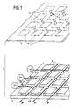
- This head 1 has for example a topology as described in the French Patent Application n ° 88 05592 published on 3.11.89 under the publication number FR-A-2 630 853 and therefore not forming part of the state of the technical within the meaning of article 54 (2) EPC. and represented in FIG. 1.
- the production of the micro-heads and the network of wires are different.
- this head 1 essentially comprises, for the embodiment shown, a base plate 2 of material with low relative magnetic permeability, such as ferrite.
- a substantially orthogonal network of grooves is practiced in lines (RL1, RL2 ...) and in columns (RC1, RC2 ).
- Line conductors L1, L2, ... and columns C1, C2, ... are arranged in these grooves.
- This network of grooves determines on the plate 2 pavers 3 whose upper face is substantially square, preferably slightly trapezoidal for the reasons explained below.
- the plate 2 is covered with a plate 4 of the same surface made of non-magnetic material, for example glass, on which is deposited a network of pole pieces 5 made of material with high relative permeability, such as "Permalloy” or “Sendust” .
- pole pieces 5 have the shape of rectangles all parallel to one of the diagonals of the plate 4, joining the corners facing blocks 3 arranged symmetrically with respect to the crossing of a line groove and a column groove (such as blocks 3A, 3B).
- the plate 4 As shown in broken lines on the plate 4, it is possible to deposit on this plate 4 pole pieces 6 having the same shape and the same surface (or a slightly larger surface) than the blocks 3 with respect to which they are centered, the pieces 6 being made with the same material as the parts 5 and at the same time as the latter.
- the row and column conductors are arranged in the corresponding grooves of the plate 2 and these grooves are filled with a non-magnetic material (resin, glass, etc.).
- the upper face of the plate 2 is then polished, and the parts 5 are deposited there directly.
- the parts 5 are cut in the middle by a gap 7.
- each micro-head 8 has a magnetic circuit whose body 9 is consisting of two blocks 3A, 3B (as defined above and having one of their diagonals coinciding with the extension of the other: section line 10 in FIG. 3) and the corresponding part of the plate 2.
- This body 9 is made of a low reluctance material, for example ferrite.
- This body 9 has roughly the shape of a "U", the opening, of a width of about 30 micrometers to 1 mm, can be filled with a non-magnetic material 11, for example glass.
- the upper face of the body 9 thus filled is polished and its central part (namely the upper face of the material 11 and of the corners facing the blocks 3A, 3B) is covered with a thin layer 5 (for example d 'about 0.1 ⁇ m thick) of material with high magnetic reluctance, for example "permalloy".
- This layer 5 has for example a rectangle shape cut in its middle by the air gap 7.
- the air gap 7 has a width of about 0.3 for example. As shown in broken lines in FIG.
- the row conductors are substantially orthogonal to the column conductors, at least in the crossing of each magnetic circuit, that is to say in the region of their mutual crossing.
- a part of the wires serve to produce the excitation of the individual micro-heads.
- a DC current bias I B is applied to them, to which is superimposed, for the lines to be excited, an "RF" component, that is to say a very high frequency wave train.
- the frequency of this wave train is chosen so that during a period of excitation (or validation) of the lines in question, at least ten alternations of these waves are sent.
- Each column wire is connected to a detection circuit collecting the signal read on the magnetic tape, which is possible thanks to the fact that the pieces 5 are oblique with respect to the column wires which can thus capture the variations in flow passing through these rooms.
- a magnetic head 1 is arranged in a slightly oblique fashion (a few degrees) relative to the direction of travel of the magnetic strip 21, so as to be able to read a maximum number of tracks of this strip. without reducing unrealistically (below a few tens of microns) the pitch of the micro-heads of head 1.
- the head 1 has 4 rows (L1 to L4) and 4 columns (A to D) of micro-heads.
- the head 1 is arranged in such a way that the micro-heads (only the air gaps 7 of these micro-heads are represented in FIG. 5) cooperate with the successive tracks in the following manner, if the first track is called P1 and P16 the last: track P1 cooperates with the first micro-head (of line L1) of the first column (A), track P2 with the second micro-head (of line L2) of the first column, .. ., track P4 with the fourth micro-head (line L4) of the first column, track P5 with the first micro-head of the second column (B), and so on up to track P16 which cooperates with the fourth micro-head of the fourth column.
- the first track is called P1 and P16 the last: track P1 cooperates with the first micro-head (of line L1) of the first column (A), track P2 with the second micro-head (of line L2) of the first column, .. ., track P4 with the fourth micro-head (line L4) of the first column, track P5 with the first micro-
- the different lines L1 to L4 are perpendicular to the direction of travel of the magnetic strip, in order to standardize different types of heads.
- the air gaps of the micro-heads corresponding to successive tracks are alternately oriented in first and second directions, these two directions being substantially symmetrical with respect to a perpendicular to the direction of travel of the strip, and making with respect to at this perpendicular an angle of approximately 10 to 45 ° (see for example in the remote detail view of FIG. 5 the first two micro-heads T1 and T2 which make an angle + a and an angle -a respectively with respect to the straight line D which is perpendicular to the direction of travel of the strip).
- bursts of RF oscillations are sent cyclically to the lines L1 to L4, as shown at the top of FIG. 6.
- the signals read by the respective micro-heads A1 to A4 for column A, B1 to B4 for column B, etc. (A1 being the micro-head of column A on line L1, ). Then just process the signals in the different columns in the correct order.
- the current I B of the unexcited lines is suppressed.
- the sensitivity of the micro-heads is increased by adjusting the frequency of the RF signal to a value close to the resonance frequency of the distributed circuit formed by the corresponding line and the micro-heads. which border it.
- all the lines are simultaneously excited, but at different frequencies, and there are corresponding filters on the different columns.
Claims (14)
- Statischer Magnetband-Lesemagnetkopf, gekennzeichnet durch eine Grundplatte (2) aus einem Material mit schwacher relativer magnetischer Permeabilität, in der ein im wesentlichen orthogonales Gitter aus Nuten in Zeilen (RL1, RL2, ...) und Spalten (RC1, RC2, ...) angebracht sind, wobei eine Gruppe von Zeilenleitern (L1, L2, ...) und eine Gruppe von Spaltenleitern (C1, C2, ...) in den Nuten angeordnet sind, wobei die Grundplatte durch eine Platte (4) der gleichen Fläche aus nichtmagnetischem Material gedeckt ist, auf der eine Matrix aus Polstücken (5) angebracht ist, die jeweils einen Elementarkopf mit Luftspalt (7) bilden, wobei alle diese Köpfe parallel zu einer der Diagonalen der Platte verlaufen, auf der sie angeordnet sind, wobei diese Polstücke aus einem Material mit starker relativer magnetischer Permeabilität bestehen und die einander gegenüberliegenden Ecken von Blöcken (3) verbinden, die durch die Nuten begrenzt sind und symmetrisch bezüglich der Überkreuzung einer Zeilennut und einer Spaltennut angeordnet sind.
- Kopf nach Anspruch 1, dadurch gekennzeichnet, daß er an eine Schaltung zum Abtasten der Zeilen und zum Abtasten der Bänder angeschlossen ist.
- Kopf nach einem der vorhergehenden Ansprüche, dadurch gekennzeichnet, daß die Gruppen von Drähten, die ein Gitter bilden, im wesentlichen orthogonal verlaufen und daß der Luftspalt jedes Elementarkopfs schräg bezüglich der Drähte des Gitters verläuft.
- Kopf nach einem der vorhergehenden Ansprüche, dadurch gekennzeichnet, daß die Grundplatte jedes Magnetkreises aus einem Material mit schwacher relativer Permeabilität wie Ferrit besteht und daß die Polstücke aus einem Material mit starker magnetischer Permeabilität wie Permalloy oder Sendust bestehen.
- Kopf nach einem der vorhergehenden Ansprüche, dadurch gekennzeichnet, daß die Länge (L) der über dem Luftspalt (11) der Blöcke liegenden Polstücke (5) im wesentlichen gleich dem Produkt aus der relativen Permeabilität dieser nichtlinearen Teile und ihrer Dicke ist.
- Kopf nach einem der vorhergehenden Ansprüche mit einem Netz aus zeilen- und spaltenweise angeordneten Elementarköpfen, dadurch gekennzeichnet, daß die Zeilen der Elementarköpfe schräg bezüglich der Richtung der Vorbeibewegung des zu lesenden Bandes verlaufen.
- Kopf nach Anspruch 6, dadurch gekennzeichnet, daß die Spalten der Elementarköpfe senkrecht zur Richtung der Vorbeibewegung des Bandes verlaufen.
- Verfahren nach einem der vorhergehenden Ansprüche, dadurch gekennzeichnet, daß die Luftspalte der Elementarköpfe entsprechend den aufeinanderfolgenden Spuren des zu lesenden Bandes abwechselnd gemäß einer ersten und einer zweiten Richtung (+a, -a) ausgerichtet sind, wobei diese zwei Richtungen im wesentlichen symmetrisch bezüglich einer Senkrechten zur Richtung der Vorbeibewegung des Bandes verlaufen.
- Kopf nach Anspruch 8, dadurch gekennzeichnet, daß die zwei Richtungen einen Winkel von etwa 10 bis 45° bezüglich der Senkrechten bilden.
- Verfahren zum Lesen eines Magnetbandes unter Verwendung eines statischen Lese-Magnetkopfs nach einem der Ansprüche 1 bis 13, enthaltend die folgenden Stufen:- eine der Leitergruppen (L1, L2, ... oder C1, C2, ...) wird mit Gleichstrom gespeist,- dem Gleichstrom werden Hochfrequenzsignale überlagert,- an der anderen Gruppe von Leitern werden die an diesen Leitern erscheinenden Signale erfaßt, die die Änderungen des durch die Polstücke (5) des Kopfs verlaufenden Flusses beim Lesen des Magnetbandes aufnehmen.
- Verfahren nach Anspruch 10, dadurch gekennzeichnet, daß die Hochfrequenzsignale Wellenzüge mit einer solchen Frequenz sind, daß während einer Anregungsperiode der angeregten Zeilen wenigstens zehn Halbperioden dieser Wellen übertragen werden.
- Verfahren nach einem der Ansprüche 10 oder 11, dadurch gekennzeichnet, daß der Gleichstrom nur an die Anregungsdrähte von anzuregenden Elementarköpfen angelegt wird.
- Verfahren nach einem der Ansprüche 10 bis 12, dadurch gekennzeichnet, daß die Frequenz des Hochfrequenzsignals einen Wert hat, der nahe der Resonanzfrequenz der von der entsprechenden Leitung und den an sie angrenzenden Elementarköpfen gebildeten verteilten Schaltung liegt.
- Verfahren nach einem der Ansprüche 10 bis 13, dadurch gekennzeichnet, daß alle Zeilen der Anregungsdrähte gleichzeitig, aber mit unterschiedlichen Frequenzen, angeregt werden und daß an den verschiedenen Spalten entsprechende Filter angebracht werden.
Applications Claiming Priority (2)
| Application Number | Priority Date | Filing Date | Title |
|---|---|---|---|
| FR8904965 | 1989-04-14 | ||
| FR8904965A FR2646000B1 (fr) | 1989-04-14 | 1989-04-14 | Tete magnetique statique de lecture |
Publications (2)
| Publication Number | Publication Date |
|---|---|
| EP0392906A1 EP0392906A1 (de) | 1990-10-17 |
| EP0392906B1 true EP0392906B1 (de) | 1995-09-20 |
Family
ID=9380741
Family Applications (1)
| Application Number | Title | Priority Date | Filing Date |
|---|---|---|---|
| EP90400950A Expired - Lifetime EP0392906B1 (de) | 1989-04-14 | 1990-04-06 | Statischer Lese-Magnetkopf |
Country Status (6)
| Country | Link |
|---|---|
| US (1) | US5089923A (de) |
| EP (1) | EP0392906B1 (de) |
| JP (1) | JP3018389B2 (de) |
| KR (1) | KR100188239B1 (de) |
| DE (1) | DE69022465T2 (de) |
| FR (1) | FR2646000B1 (de) |
Families Citing this family (15)
| Publication number | Priority date | Publication date | Assignee | Title |
|---|---|---|---|---|
| FR2648607B1 (fr) * | 1989-06-16 | 1995-12-15 | Thomson Csf | Tete magnetique integree d'enregistrement |
| FR2665010B1 (fr) * | 1990-07-20 | 1992-09-18 | Thomson Csf | Dispositif magnetique de lecture a reseau matriciel de tetes de lecture. |
| US5883750A (en) * | 1992-12-22 | 1999-03-16 | Thomson-Csf | Method and system for the magnetic recording of information elements and information medium by providing current correction for cross-talk magnetic flux |
| FR2712419B1 (fr) * | 1993-11-09 | 1995-12-22 | Thomson Csf | Tête magnétique d'enregistrement/lecture. |
| FR2723242B1 (fr) * | 1994-07-26 | 1996-08-30 | Thomson Csf | Tete magnetique a element saturable et dispositif matriciel comportant un ensemble de tetes magnetiques |
| FR2727555B1 (fr) * | 1994-11-25 | 1996-12-20 | Thomson Csf | Tete magnetique d'enregistrement/lecture et son procede de realisation |
| US5606474A (en) * | 1995-01-17 | 1997-02-25 | Latsu, Inc. | High density disk drive with accelerated disk access |
| FR2735269B1 (fr) * | 1995-06-06 | 1997-07-25 | Thomson Csf | Tete d'enregistrement/lecture matricielle a structure zigzag |
| EP0830670A1 (de) * | 1995-06-07 | 1998-03-25 | Seagate Technology, Inc. | Kopfoberfläche mit ebener topographie auf einem kopf mit gemustertem pol |
| FR2738657B1 (fr) * | 1995-09-12 | 1997-10-03 | Thomson Csf | Tete magnetique d'enregistrement/lecture |
| FR2786345B1 (fr) | 1998-11-24 | 2001-02-09 | Thomson Csf | Dispositif de cryptage quantique |
| US7149173B2 (en) * | 2000-10-17 | 2006-12-12 | Thales | Medium for recording optically readable data, method for making same and optical system reproducing said data |
| FR2824905B1 (fr) * | 2001-05-15 | 2003-08-29 | Thomson Csf | Gyrometre a fibre optique |
| US7153168B2 (en) | 2004-04-06 | 2006-12-26 | Panduit Corp. | Electrical connector with improved crosstalk compensation |
| EP1987569A1 (de) * | 2006-02-13 | 2008-11-05 | Panduit Corp. | Verbinder mit übersprechkompensation |
Family Cites Families (8)
| Publication number | Priority date | Publication date | Assignee | Title |
|---|---|---|---|---|
| US2762861A (en) * | 1954-08-30 | 1956-09-11 | Rca Corp | Magnetic video recording and reproducing |
| US3662361A (en) * | 1968-02-13 | 1972-05-09 | Ibm | Magnetic head with deposited core and signal conductor |
| US3626396A (en) * | 1968-10-03 | 1971-12-07 | Ibm | Thin-film magnetic recording head |
| DE2124912A1 (de) * | 1970-05-21 | 1972-01-27 | Sperry Rand Corp | Magnetischer Lesekopf |
| US4423450A (en) * | 1981-05-06 | 1983-12-27 | Censtor Corporation | Magnetic head and multitrack transducer for perpendicular recording and method for fabricating |
| JPS6139914A (ja) * | 1984-07-31 | 1986-02-26 | Konishiroku Photo Ind Co Ltd | 磁気ヘツド |
| US4751598A (en) * | 1985-02-01 | 1988-06-14 | Censtor Corporation | Thin-film, cross-field, closed-flux, anisotropic electromagnetic field device |
| FR2630244B1 (fr) * | 1988-04-15 | 1990-07-13 | Commissariat Energie Atomique | Dispositif d'ecriture et de lecture sur un support magnetique et son procede de fabrication |
-
1989
- 1989-04-14 FR FR8904965A patent/FR2646000B1/fr not_active Expired - Fee Related
-
1990
- 1990-04-06 DE DE69022465T patent/DE69022465T2/de not_active Expired - Fee Related
- 1990-04-06 US US07/506,221 patent/US5089923A/en not_active Expired - Fee Related
- 1990-04-06 EP EP90400950A patent/EP0392906B1/de not_active Expired - Lifetime
- 1990-04-12 KR KR1019900005074A patent/KR100188239B1/ko not_active IP Right Cessation
- 1990-04-13 JP JP2096626A patent/JP3018389B2/ja not_active Expired - Lifetime
Also Published As
| Publication number | Publication date |
|---|---|
| DE69022465T2 (de) | 1996-02-08 |
| US5089923A (en) | 1992-02-18 |
| JPH02292708A (ja) | 1990-12-04 |
| DE69022465D1 (de) | 1995-10-26 |
| KR900016949A (ko) | 1990-11-14 |
| KR100188239B1 (ko) | 1999-06-01 |
| FR2646000B1 (fr) | 1995-07-21 |
| EP0392906A1 (de) | 1990-10-17 |
| JP3018389B2 (ja) | 2000-03-13 |
| FR2646000A1 (fr) | 1990-10-19 |
Similar Documents
| Publication | Publication Date | Title |
|---|---|---|
| EP0392906B1 (de) | Statischer Lese-Magnetkopf | |
| EP0418372B1 (de) | Lese-magnetkopf mit magnetowiderstand für senkrechte aufzeichnung und herstellungsverfahren eines derartigen kopfes | |
| EP0340085B1 (de) | Magnetkopf-Matrixanordnung, insbesondere aus Dünnfilmen | |
| EP0420755B1 (de) | Herstellungsverfahren eines Magnetaufzeichnungskopfes und nach diesem Verfahren erhaltener Kopf | |
| EP0270404B1 (de) | Anordnung magnetischer Pole, Anwendung in einem Schreib/Lese-Magnetkopf und Herstellungsverfahren | |
| CA2047185C (fr) | Tete de lecture multipiste magneto-optique | |
| EP0284495A2 (de) | Magnetkopf zum Lesen von Spuren mit sehr schmaler Breite und Herstellungverfahren | |
| EP0429598B1 (de) | Mehrspur-aufnahmemagnetkopf mit kompakter matrixartiger struktur | |
| EP0409675B1 (de) | Mehrspur-Magnetkopf mit grossem Feldkontrast | |
| EP0642030A1 (de) | Flussleiter mit Zungen und magnetischer Sensor mit einem solchen Flussleiter | |
| KR100230667B1 (ko) | 고해상도자기-광학판독헤드 | |
| FR2774797A1 (fr) | Procede de realisation d'un ensemble a plusieurs tetes magnetiques et ensemble a tetes multiples obtenu par ce procede | |
| EP0642181A1 (de) | Magnetoresistive Anordnung und Fühler mit wiederholenden geometrischen Strukturen | |
| EP0434547B1 (de) | Mehrspur-Lesemagnetkopf | |
| EP0694909B1 (de) | Magnetkopf mit sättigbarem Element und Matrixanordnung bestehend aus einem Satz von Magnetköpfen | |
| EP0188943B1 (de) | Schreib-Magnetwandler zur transversalen Aufzeichnung | |
| EP0800160B1 (de) | Herstellungsverfahren für einen Doppel-Magnetkopf mit entgegengesetzten Azimuth-Spalten | |
| EP0028177B1 (de) | Integrierter Magnetwandler | |
| FR2558000A1 (fr) | Tete de transducteur magnetique. | |
| EP0132186B1 (de) | Höchstintegrierter Magnetwandler zum Schreiben von Informationen auf einem magnetischen Träger | |
| FR2723243A1 (fr) | Dispositif d'enregistrement et/ou de lecture de tetes magnetiques et son procede de realisation | |
| RU2115962C1 (ru) | Магнитно-оптическая головка для считывания информации | |
| FR2493015A1 (fr) | Transducteur magnetoresistant |
Legal Events
| Date | Code | Title | Description |
|---|---|---|---|
| PUAI | Public reference made under article 153(3) epc to a published international application that has entered the european phase |
Free format text: ORIGINAL CODE: 0009012 |
|
| AK | Designated contracting states |
Kind code of ref document: A1 Designated state(s): DE GB NL |
|
| 17P | Request for examination filed |
Effective date: 19910318 |
|
| 17Q | First examination report despatched |
Effective date: 19930920 |
|
| RAP1 | Party data changed (applicant data changed or rights of an application transferred) |
Owner name: THOMSON-CSF |
|
| GRAA | (expected) grant |
Free format text: ORIGINAL CODE: 0009210 |
|
| AK | Designated contracting states |
Kind code of ref document: B1 Designated state(s): DE GB NL |
|
| REF | Corresponds to: |
Ref document number: 69022465 Country of ref document: DE Date of ref document: 19951026 |
|
| GBT | Gb: translation of ep patent filed (gb section 77(6)(a)/1977) |
Effective date: 19951127 |
|
| PLBE | No opposition filed within time limit |
Free format text: ORIGINAL CODE: 0009261 |
|
| STAA | Information on the status of an ep patent application or granted ep patent |
Free format text: STATUS: NO OPPOSITION FILED WITHIN TIME LIMIT |
|
| 26N | No opposition filed | ||
| PGFP | Annual fee paid to national office [announced via postgrant information from national office to epo] |
Ref country code: NL Payment date: 20010314 Year of fee payment: 12 |
|
| PGFP | Annual fee paid to national office [announced via postgrant information from national office to epo] |
Ref country code: DE Payment date: 20010319 Year of fee payment: 12 |
|
| PGFP | Annual fee paid to national office [announced via postgrant information from national office to epo] |
Ref country code: GB Payment date: 20010321 Year of fee payment: 12 |
|
| REG | Reference to a national code |
Ref country code: GB Ref legal event code: IF02 |
|
| PG25 | Lapsed in a contracting state [announced via postgrant information from national office to epo] |
Ref country code: GB Free format text: LAPSE BECAUSE OF NON-PAYMENT OF DUE FEES Effective date: 20020406 |
|
| PG25 | Lapsed in a contracting state [announced via postgrant information from national office to epo] |
Ref country code: NL Free format text: LAPSE BECAUSE OF NON-PAYMENT OF DUE FEES Effective date: 20021101 Ref country code: DE Free format text: LAPSE BECAUSE OF NON-PAYMENT OF DUE FEES Effective date: 20021101 |
|
| GBPC | Gb: european patent ceased through non-payment of renewal fee |
Effective date: 20020406 |
|
| NLV4 | Nl: lapsed or anulled due to non-payment of the annual fee |
Effective date: 20021101 |