EP0392906B1 - Static magnetic read head - Google Patents
Static magnetic read head Download PDFInfo
- Publication number
- EP0392906B1 EP0392906B1 EP90400950A EP90400950A EP0392906B1 EP 0392906 B1 EP0392906 B1 EP 0392906B1 EP 90400950 A EP90400950 A EP 90400950A EP 90400950 A EP90400950 A EP 90400950A EP 0392906 B1 EP0392906 B1 EP 0392906B1
- Authority
- EP
- European Patent Office
- Prior art keywords
- head
- magnetic
- heads
- head according
- tape
- Prior art date
- Legal status (The legal status is an assumption and is not a legal conclusion. Google has not performed a legal analysis and makes no representation as to the accuracy of the status listed.)
- Expired - Lifetime
Links
- 230000003068 static effect Effects 0.000 title claims description 7
- 239000004020 conductor Substances 0.000 claims description 18
- 239000000463 material Substances 0.000 claims description 17
- 230000035699 permeability Effects 0.000 claims description 10
- 238000000034 method Methods 0.000 claims description 8
- 230000005284 excitation Effects 0.000 claims description 7
- 239000000696 magnetic material Substances 0.000 claims description 5
- 229910000889 permalloy Inorganic materials 0.000 claims description 4
- 230000004907 flux Effects 0.000 claims description 3
- 229910000859 α-Fe Inorganic materials 0.000 claims description 3
- 229910000702 sendust Inorganic materials 0.000 claims description 2
- 238000010408 sweeping Methods 0.000 claims 1
- 210000003128 head Anatomy 0.000 description 21
- 239000011521 glass Substances 0.000 description 3
- 238000001514 detection method Methods 0.000 description 2
- 238000010586 diagram Methods 0.000 description 2
- 238000004519 manufacturing process Methods 0.000 description 2
- 239000011159 matrix material Substances 0.000 description 2
- 230000035945 sensitivity Effects 0.000 description 2
- 238000012550 audit Methods 0.000 description 1
- 239000000470 constituent Substances 0.000 description 1
- 230000008878 coupling Effects 0.000 description 1
- 238000010168 coupling process Methods 0.000 description 1
- 238000005859 coupling reaction Methods 0.000 description 1
- 238000006073 displacement reaction Methods 0.000 description 1
- 230000006698 induction Effects 0.000 description 1
- 238000009434 installation Methods 0.000 description 1
- 230000005415 magnetization Effects 0.000 description 1
- 230000010355 oscillation Effects 0.000 description 1
- 230000003071 parasitic effect Effects 0.000 description 1
- 239000011347 resin Substances 0.000 description 1
- 229920005989 resin Polymers 0.000 description 1
- 210000001525 retina Anatomy 0.000 description 1
- 238000010200 validation analysis Methods 0.000 description 1
Images


Classifications
-
- G—PHYSICS
- G11—INFORMATION STORAGE
- G11B—INFORMATION STORAGE BASED ON RELATIVE MOVEMENT BETWEEN RECORD CARRIER AND TRANSDUCER
- G11B5/00—Recording by magnetisation or demagnetisation of a record carrier; Reproducing by magnetic means; Record carriers therefor
- G11B5/127—Structure or manufacture of heads, e.g. inductive
- G11B5/33—Structure or manufacture of flux-sensitive heads, i.e. for reproduction only; Combination of such heads with means for recording or erasing only
-
- G—PHYSICS
- G11—INFORMATION STORAGE
- G11B—INFORMATION STORAGE BASED ON RELATIVE MOVEMENT BETWEEN RECORD CARRIER AND TRANSDUCER
- G11B5/00—Recording by magnetisation or demagnetisation of a record carrier; Reproducing by magnetic means; Record carriers therefor
- G11B5/48—Disposition or mounting of heads or head supports relative to record carriers ; arrangements of heads, e.g. for scanning the record carrier to increase the relative speed
- G11B5/49—Fixed mounting or arrangements, e.g. one head per track
- G11B5/4969—Details for track selection or addressing
-
- G—PHYSICS
- G11—INFORMATION STORAGE
- G11B—INFORMATION STORAGE BASED ON RELATIVE MOVEMENT BETWEEN RECORD CARRIER AND TRANSDUCER
- G11B5/00—Recording by magnetisation or demagnetisation of a record carrier; Reproducing by magnetic means; Record carriers therefor
- G11B5/127—Structure or manufacture of heads, e.g. inductive
- G11B5/33—Structure or manufacture of flux-sensitive heads, i.e. for reproduction only; Combination of such heads with means for recording or erasing only
- G11B5/332—Structure or manufacture of flux-sensitive heads, i.e. for reproduction only; Combination of such heads with means for recording or erasing only using thin films
-
- G—PHYSICS
- G11—INFORMATION STORAGE
- G11B—INFORMATION STORAGE BASED ON RELATIVE MOVEMENT BETWEEN RECORD CARRIER AND TRANSDUCER
- G11B5/00—Recording by magnetisation or demagnetisation of a record carrier; Reproducing by magnetic means; Record carriers therefor
- G11B5/48—Disposition or mounting of heads or head supports relative to record carriers ; arrangements of heads, e.g. for scanning the record carrier to increase the relative speed
- G11B5/49—Fixed mounting or arrangements, e.g. one head per track
- G11B5/4907—Details for scanning
Definitions
- the present invention relates to a static magnetic reading head.
- a rotating magnetic head (of the "heliscan” type) is generally used, making it possible to record a large number of tracks, then to replay them .
- Such a magnetic head presents manufacturing and installation difficulties because it is mobile and must be positioned with great precision.
- magneto-optical transducers associated with retinas in CCD technique are also known. These reading systems also require very precise positioning of their constituents.
- the present invention relates to a static read head allowing the reading of the magnetic tapes recorded in a conventional manner, which is low cost and easy to install.
- the read head according to the invention is a static magnetic head for reading a magnetic strip, which is characterized by the fact that it comprises a base plate made of material with low relative magnetic permeability, in which a substantially orthogonal network is practiced. grooves in rows and columns, a group of row conductors and a group of column conductors being arranged in these grooves, this base plate being covered with a plate of the same surface, made of non-magnetic material, on which is deposited a network of pole pieces each time forming an elementary head for air gap, all the heads being parallel to one of the diagonals of the plate on which they are deposited, these pieces being made of material with high relative magnetic permeability and joining the corners in with respect to blocks delimited by said grooves and arranged symmetrically with respect to the intersection of a line groove and a column groove, and by the fact that one of the groups of conductors is supplied with direct current to which high frequency signals are superimposed, and each wire of the other group of conductors is connected to a detection circuit.
- the head magnetic is connected to a line scanning and band scanning circuit.
- said wires form a substantially orthogonal network, and the linear part of the magnetic circuit has symmetry, the non-linear element of this magnetic circuit being oblique with respect to the wires of the network.
- the magnetic reading head 1 is formed of a dense network of micro-heads (elementary heads) reading arranged in a matrix.
- This matrix can for example comprise 16 lines of 16 micro-heads each, for reading a video magnetic tape.
- This head 1 has for example a topology as described in the French Patent Application n ° 88 05592 published on 3.11.89 under the publication number FR-A-2 630 853 and therefore not forming part of the state of the technical within the meaning of article 54 (2) EPC. and represented in FIG. 1.
- the production of the micro-heads and the network of wires are different.
- this head 1 essentially comprises, for the embodiment shown, a base plate 2 of material with low relative magnetic permeability, such as ferrite.
- a substantially orthogonal network of grooves is practiced in lines (RL1, RL2 ...) and in columns (RC1, RC2 ).
- Line conductors L1, L2, ... and columns C1, C2, ... are arranged in these grooves.
- This network of grooves determines on the plate 2 pavers 3 whose upper face is substantially square, preferably slightly trapezoidal for the reasons explained below.
- the plate 2 is covered with a plate 4 of the same surface made of non-magnetic material, for example glass, on which is deposited a network of pole pieces 5 made of material with high relative permeability, such as "Permalloy” or “Sendust” .
- pole pieces 5 have the shape of rectangles all parallel to one of the diagonals of the plate 4, joining the corners facing blocks 3 arranged symmetrically with respect to the crossing of a line groove and a column groove (such as blocks 3A, 3B).
- the plate 4 As shown in broken lines on the plate 4, it is possible to deposit on this plate 4 pole pieces 6 having the same shape and the same surface (or a slightly larger surface) than the blocks 3 with respect to which they are centered, the pieces 6 being made with the same material as the parts 5 and at the same time as the latter.
- the row and column conductors are arranged in the corresponding grooves of the plate 2 and these grooves are filled with a non-magnetic material (resin, glass, etc.).
- the upper face of the plate 2 is then polished, and the parts 5 are deposited there directly.
- the parts 5 are cut in the middle by a gap 7.
- each micro-head 8 has a magnetic circuit whose body 9 is consisting of two blocks 3A, 3B (as defined above and having one of their diagonals coinciding with the extension of the other: section line 10 in FIG. 3) and the corresponding part of the plate 2.
- This body 9 is made of a low reluctance material, for example ferrite.
- This body 9 has roughly the shape of a "U", the opening, of a width of about 30 micrometers to 1 mm, can be filled with a non-magnetic material 11, for example glass.
- the upper face of the body 9 thus filled is polished and its central part (namely the upper face of the material 11 and of the corners facing the blocks 3A, 3B) is covered with a thin layer 5 (for example d 'about 0.1 ⁇ m thick) of material with high magnetic reluctance, for example "permalloy".
- This layer 5 has for example a rectangle shape cut in its middle by the air gap 7.
- the air gap 7 has a width of about 0.3 for example. As shown in broken lines in FIG.
- the row conductors are substantially orthogonal to the column conductors, at least in the crossing of each magnetic circuit, that is to say in the region of their mutual crossing.
- a part of the wires serve to produce the excitation of the individual micro-heads.
- a DC current bias I B is applied to them, to which is superimposed, for the lines to be excited, an "RF" component, that is to say a very high frequency wave train.
- the frequency of this wave train is chosen so that during a period of excitation (or validation) of the lines in question, at least ten alternations of these waves are sent.
- Each column wire is connected to a detection circuit collecting the signal read on the magnetic tape, which is possible thanks to the fact that the pieces 5 are oblique with respect to the column wires which can thus capture the variations in flow passing through these rooms.
- a magnetic head 1 is arranged in a slightly oblique fashion (a few degrees) relative to the direction of travel of the magnetic strip 21, so as to be able to read a maximum number of tracks of this strip. without reducing unrealistically (below a few tens of microns) the pitch of the micro-heads of head 1.
- the head 1 has 4 rows (L1 to L4) and 4 columns (A to D) of micro-heads.
- the head 1 is arranged in such a way that the micro-heads (only the air gaps 7 of these micro-heads are represented in FIG. 5) cooperate with the successive tracks in the following manner, if the first track is called P1 and P16 the last: track P1 cooperates with the first micro-head (of line L1) of the first column (A), track P2 with the second micro-head (of line L2) of the first column, .. ., track P4 with the fourth micro-head (line L4) of the first column, track P5 with the first micro-head of the second column (B), and so on up to track P16 which cooperates with the fourth micro-head of the fourth column.
- the first track is called P1 and P16 the last: track P1 cooperates with the first micro-head (of line L1) of the first column (A), track P2 with the second micro-head (of line L2) of the first column, .. ., track P4 with the fourth micro-head (line L4) of the first column, track P5 with the first micro-
- the different lines L1 to L4 are perpendicular to the direction of travel of the magnetic strip, in order to standardize different types of heads.
- the air gaps of the micro-heads corresponding to successive tracks are alternately oriented in first and second directions, these two directions being substantially symmetrical with respect to a perpendicular to the direction of travel of the strip, and making with respect to at this perpendicular an angle of approximately 10 to 45 ° (see for example in the remote detail view of FIG. 5 the first two micro-heads T1 and T2 which make an angle + a and an angle -a respectively with respect to the straight line D which is perpendicular to the direction of travel of the strip).
- bursts of RF oscillations are sent cyclically to the lines L1 to L4, as shown at the top of FIG. 6.
- the signals read by the respective micro-heads A1 to A4 for column A, B1 to B4 for column B, etc. (A1 being the micro-head of column A on line L1, ). Then just process the signals in the different columns in the correct order.
- the current I B of the unexcited lines is suppressed.
- the sensitivity of the micro-heads is increased by adjusting the frequency of the RF signal to a value close to the resonance frequency of the distributed circuit formed by the corresponding line and the micro-heads. which border it.
- all the lines are simultaneously excited, but at different frequencies, and there are corresponding filters on the different columns.
Description
La présente invention se rapporte à une tête magnétique statique de lecture.The present invention relates to a static magnetic reading head.
Pour écrire des informations telles que des signaux vidéo sur une bande magnétique, et pour lire ensuite la bande enregistrée, on utilise généralement une tête magnétique rotative (de type "héliscan") permettant d'enregistrer un grand nombre de pistes, puis de les relire. Une telle tête magnétique présente des difficultés de fabrication et de mise en place du fait qu'elle est mobile et doit être positionnée avec une grande précision.To write information such as video signals on a magnetic tape, and to then read the recorded tape, a rotating magnetic head (of the "heliscan" type) is generally used, making it possible to record a large number of tracks, then to replay them . Such a magnetic head presents manufacturing and installation difficulties because it is mobile and must be positioned with great precision.
Pour la lecture des bandes ainsi enregistrées, on connaît également des transducteurs magnéto-optiques associés à des rétines en technique CCD. Ces systèmes de lecture nécessitent également un positionnement très précis de leurs constituants.For reading the tapes thus recorded, magneto-optical transducers associated with retinas in CCD technique are also known. These reading systems also require very precise positioning of their constituents.
On connaît d'après les documents US-A-3 662 361 et FR-A-2 090 196 des têtes statiques de lecture ou d'écriture de bandes magnétiques, dont la structure est relativement complexe à réaliser.We know from documents US-A-3,662,361 and FR-A-2,090,196 static heads for reading or writing magnetic tapes, the structure of which is relatively complex to produce.
La présente invention a pour objet une tête de lecture statique permettant la lecture des bandes magnétiques enregistrées de façon conventionnelle, qui soit de faible prix de revient et facile à implanter.The present invention relates to a static read head allowing the reading of the magnetic tapes recorded in a conventional manner, which is low cost and easy to install.
La tête de lecture conforme à l'invention est une tête magnétique statique de lecture de bande magnétique, qui est caractérisée par le fait qu'elle comporte une plaque de base en matériau à faible perméabilité magnétique relative, dans laquelle est pratiqué un réseau sensiblement orthogonal de rainures en lignes et en colonnes, un groupe de conducteurs de lignes et un groupe de conducteurs de colonnes étant disposés dans ces rainures, cette plaque de base étant recouverte d'une plaque de même surface, en matériau amagnétique, sur laquelle est déposé un réseau de pièces polaires formant à chaque fois une tête élémentaire à entrefer, toutes les têtes étant parallèles à l'une des diagonales de la plaque sur laquelle elles sont déposées, ces pièces étant en matériau à forte perméabilité magnétique relative et joignant les coins en vis-à-vis de pavés délimités par lesdites rainures et disposés symétriquement par rapport au croisement d'une rainure de ligne et d'une rainure de colonne, et par le fait que l'un des groupes de conducteurs est alimenté en courant continu auquel sont superposés des signaux à haute fréquence, et que chaque fil de l'autre groupe de conducteurs est relié à un circuit de détection.The read head according to the invention is a static magnetic head for reading a magnetic strip, which is characterized by the fact that it comprises a base plate made of material with low relative magnetic permeability, in which a substantially orthogonal network is practiced. grooves in rows and columns, a group of row conductors and a group of column conductors being arranged in these grooves, this base plate being covered with a plate of the same surface, made of non-magnetic material, on which is deposited a network of pole pieces each time forming an elementary head for air gap, all the heads being parallel to one of the diagonals of the plate on which they are deposited, these pieces being made of material with high relative magnetic permeability and joining the corners in with respect to blocks delimited by said grooves and arranged symmetrically with respect to the intersection of a line groove and a column groove, and by the fact that one of the groups of conductors is supplied with direct current to which high frequency signals are superimposed, and each wire of the other group of conductors is connected to a detection circuit.
Le procédé d'utilisation de tête magnétique de l'invention est caractérisé par les étapes suivantes :
- on alimente en courant continu l'un des groupes de conducteurs (L1, L2, ... ou C1, C2, ...)
- on superpose des signaux à haute fréquence audit courant continu
- on détecte sur l'autre groupe de conducteurs les signaux apparaissant sur ces conducteurs qui captent les variations de flux passant par les pièces polaires (5) de la tête lors de la lecture de la bande magnétique.
- one of the conductor groups is supplied with direct current (L1, L2, ... or C1, C2, ...)
- high frequency signals are superimposed on said direct current
- the signals appearing on these conductors are detected on the other group of conductors which pick up the flux variations passing through the pole pieces (5) of the head when the magnetic strip is read.
Selon un mode particulier de réalisation de l'invention, la tête magnétique est reliée à un circuit de balayage de lignes et d'exploration de bande.According to a particular embodiment of the invention, the head magnetic is connected to a line scanning and band scanning circuit.
Selon encore un mode particulier de réalisation de l'invention, lesdits fils forment un réseau sensiblement orthogonal, et la partie linéaire du circuit magnétique présente une symétrie, l'élément non linéaire de ce circuit magnétique étant oblique par rapport aux fils du réseau.According to yet another particular embodiment of the invention, said wires form a substantially orthogonal network, and the linear part of the magnetic circuit has symmetry, the non-linear element of this magnetic circuit being oblique with respect to the wires of the network.
La présente invention sera mieux comprise à la lecture de la description détaillée d'un mode de réalisation, pris à titre d'exemple non limitatif, et illustré par le dessin annexé, sur lequel :
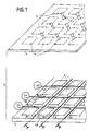
- la figure 1 est une vue partielle en perspective d'une tête magnétique ;
- la figure 2 est une vue en coupe simplifiée d'une tête élémentaire conforme à l'invention ;
- la figure 3 est une vue schématique en plan de la tête élémentaire de la figure 1 avec quelques fils de ligne et de colonnes avec lesquels elle coopère ;
- la figure 4 est un diagramme de tension d'excitation d'une ligne de la tête de la figure 1 ;
- la figure 5 est une vue schématique montrant le positionnement d'une tête conforme à l'invention par rapport à une bande magnétique qu'elle lit, et
- la figure 6 est un chronogramme de quelques signaux apparaissant dans la tête de la figure 4.
- Figure 1 is a partial perspective view of a magnetic head;
- Figure 2 is a simplified sectional view of an elementary head according to the invention;
- Figure 3 is a schematic plan view of the elementary head of Figure 1 with some row and column son with which it cooperates;
- Figure 4 is an excitation voltage diagram of a line of the head of Figure 1;
- FIG. 5 is a schematic view showing the positioning of a head according to the invention with respect to a magnetic strip which it reads, and
- FIG. 6 is a timing diagram of some signals appearing in the head of FIG. 4.
La tête magnétique 1 de lecture conforme à l'invention est formée d'un réseau dense de micro-têtes (têtes élémentaires) de lecture disposées en matrice. Cette matrice peut par exemple comporter 16 lignes de 16 micro-têtes chacune, pour lire une bande magnétique vidéo. Cette tête 1 a par exemple une topologie telle que décrite dans la Demande de Brevet français n° 88 05592 publiée le 3.11.89 sous le numéro de publication FR-A-2 630 853 et ne faisant donc pas partie de l'état de la technique au sens de l'article 54(2) EPC. et représentée en figure 1. Cependant la réalisation des micro-têtes et le réseau de fils sont différents. En effet, selon la demande précitée, les extensions (références 17₁, 18₁ dans cette demande) des pièces polaires (17,18) sont généralement réalisées avec le même matériau que ces pièces polaires. Par contre, selon la présente invention, cette tête 1 comporte essentiellement, pour le mode de réalisation représenté, une plaque de base 2 en matériau à faible perméabilité magnétique relative, tel que du ferrite. Dans cette plaque de base, on pratique un réseau sensiblement orthogonal de rainures en lignes (RL1,RL2...) et en colonnes (RC1,RC2...). Des conducteurs de lignes L1,L2,... et de colonnes C1, C2,... sont disposés dans ces rainures. Ce réseau de rainures détermine sur la plaque 2 des pavés 3 dont la face supérieure est sensiblement carrée, de préférence légèrement trapézoïdale pour les raisons expliquées ci-dessous. La plaque 2 est recouverte d'une plaque 4 de même surface en matériau amagnétique, par exemple du verre, sur laquelle est déposé un réseau de pièces polaires 5 en matériau à forte perméabilité relative, tel que du "Permalloy" ou du "Sendust". Ces pièces polaires 5 ont la forme de rectangles tous parallèles à l'une des diagonales de la plaque 4, joignant les coins en vis-à-vis de pavés 3 disposés symétriquement par rapport au croisement d'une rainure de ligne et d'une rainure de colonne (comme par exemple les pavés 3A,3B). Comme représenté en traits interrompus sur la plaque 4, on peut déposer sur cette plaque 4 des pièces polaires 6 ayant la même forme et la même surface (ou une surface légèrement plus grande) que les pavés 3 par rapport auxquels elles sont centrées, les pièces 6 étant réalisées avec le même matériau que les pièces 5 et en même temps que ces dernières. Selon un autre mode de réalisation représenté en figures 2 et 3, on dispose les conducteurs de lignes et de colonnes dans les rainures correspondantes de la plaque 2 et on remplit ces rainures d'un matériau amagnétique (résine, verre...). On polit ensuite la face supérieure de la plaque 2, et on y dépose directement les pièces 5. Les pièces 5 sont coupées en leur milieu par un entrefer 7.The magnetic reading head 1 according to the invention is formed of a dense network of micro-heads (elementary heads) reading arranged in a matrix. This matrix can for example comprise 16 lines of 16 micro-heads each, for reading a video magnetic tape. This head 1 has for example a topology as described in the French Patent Application n ° 88 05592 published on 3.11.89 under the publication number FR-A-2 630 853 and therefore not forming part of the state of the technical within the meaning of article 54 (2) EPC. and represented in FIG. 1. However, the production of the micro-heads and the network of wires are different. Indeed, according to the above-mentioned request, the extensions (references 17₁, 18₁ in this request) of the pole pieces (17,18) are generally made with the same material as these pole pieces. On the other hand, according to the present invention, this head 1 essentially comprises, for the embodiment shown, a
Ainsi que représenté en détail sur la figure 2, chaque micro-tête 8 a un circuit magnétique dont le corps 9 est constitué par deux pavés 3A,3B (tels que définis ci-dessus et ayant une de leurs diagonales confondue avec le prolongement de l'autre : ligne de coupe 10 sur la figure 3) et la partie correspondante de la plaque 2. Ce corps 9 est réalisé en un matériau à faible réluctance, par exemple du ferrite. Ce corps 9 a à peu près la forme d'un "U" dont l'ouverture, d'une largeur d'environ 30 micromètres à 1 mm, peut être remplie d'un matériau amagnétique 11, par exemple du verre. La face supérieure du corps 9 ainsi rempli est polie et sa partie centrale (à savoir la face supérieure du matériau 11 et des coins en vis-à-vis des pavés 3A,3B) est recouverte d'une mince couche 5 (par exemple d'environ 0,1 µm d'épaisseur) de matériau à forte réluctance magnétique, par exemple du "permalloy". Cette couche 5 a par exemple une forme de rectangle coupé en son milieu par l'entrefer 7. L'entrefer 7 a une largeur d'environ 0,3 par exemple. Comme représenté en traits interrompus en figure 2, on peut recouvrir la totalité de la surface des pavés 3A,3B avec ce matérlau à forte réluctance, ce qui ne nuit pratiquement pas au fonctionnement de la micro-tête, puisque la condition importante à respecter est que la partie de la couche située entre les branches dudit "U" ait une faible largeur par rapport aux dimensions des pavés 3.As shown in detail in Figure 2, each micro-head 8 has a magnetic circuit whose
Dans la cavité 12 entourée par le corps 3, passent un conducteur de colonne 13 et un conducteur de ligne 14.In the cavity 12 surrounded by the
De préférence, les conducteurs de lignes sont sensiblement orthogonaux aux conducteurs de colonnes, au moins dans la traversée de chaque circuit magnétique, c'est-à-dire dans la zone de leur croisement mutuel.Preferably, the row conductors are substantially orthogonal to the column conductors, at least in the crossing of each magnetic circuit, that is to say in the region of their mutual crossing.
Si l'on appelle L la longueur de la partie de la couche 5 située sur le matériau 11, µr sa perméabilité relative, et e son épaisseur, L doit être sensiblement égale au produit µr.e. Si par exemple µr=1000 et e=0, 1 µm, on trouve pour L une valeur de 100 µm.If we call L the length of the part of the
Une partie des fils, par exemple les fils de lignes, servent à produire l'excitation des micro-têtes individuelles. A cet effet, on leur applique une polarisation de courant continu IB à laquelle on superpose, pour les lignes à exciter, une composante "RF", c'est-à-dire un train d'ondes à très haute fréquence. La fréquence de ce train d'ondes est choisie de façon que pendant une période d'excitation (ou de validation) des lignes en question on envoie au moins une dizaine d'alternances de ces ondes. Comme on peut le voir d'après la caractéristique M= f(H) (M étant l'énergie de magnétisation des éléments non linéaires 5, et H le champ) d'un matériau à propriétés magnétiques non linéaires tel que le "Permalloy", excité selon son axe difficile, il faut déplacer le point de fonctionnement d'un tel matériau vers une zone à faible rayon de courbure (zone du point A sur la figure 4) pour laquelle la sensibilité des circuits magnétiques de l'invention est la plus élevée. Le déplacement du point de fonctionnement est obtenu par ledit courant continu IB de polarisation, donnant un champ HB.A part of the wires, for example the line wires, serve to produce the excitation of the individual micro-heads. AT For this purpose, a DC current bias I B is applied to them, to which is superimposed, for the lines to be excited, an "RF" component, that is to say a very high frequency wave train. The frequency of this wave train is chosen so that during a period of excitation (or validation) of the lines in question, at least ten alternations of these waves are sent. As can be seen from the characteristic M = f (H) (M being the magnetization energy of the
Chaque fil de colonne est relié à un circuit de détection recueillant le signal lu sur la bande magnétique, ce qui est possible grâce au fait que les pièces 5 sont obliques par rapport aux fils de colonnes qui peuvent ainsi capter les variations de flux passant par ces pièces.Each column wire is connected to a detection circuit collecting the signal read on the magnetic tape, which is possible thanks to the fact that the
De façon avantageuse, comme représenté en figure 5, une tête magnétique 1 est disposée de façon légèrement oblique (quelques degrés) par rapport à la direction de défilement de la bande magnétique 21, de façon à pouvoir lire un nombre maximal de pistes de cette bande sans réduire pour autant de façon irréaliste (en dessous de quelques dizaines de microns) le pas des micro-têtes de la tête 1.Advantageously, as shown in FIG. 5, a magnetic head 1 is arranged in a slightly oblique fashion (a few degrees) relative to the direction of travel of the
Pour simplifier les explications, on suppose que la tête 1 comporte 4 lignes (L1 à L4) et 4 colonnes (A à D) de micro-têtes.To simplify the explanations, it is assumed that the head 1 has 4 rows (L1 to L4) and 4 columns (A to D) of micro-heads.
La tête 1 est disposée de telle façon que les micro-têtes (seuls les entrefers 7 de ces micro-têtes sont représentés en figure 5) coopèrent avec les pistes successives de la manière suivante, si l'on appelle P1 la première piste et P16 la dernière : la piste P1 coopère avec la première micro-tête (de la ligne L1) de la première colonne (A), la piste P2 avec la deuxième micro-tête (de la ligne L2) de la première colonne,..., la piste P4 avec la quatrième micro-tête (ligne L4) de la première colonne, la piste P5 avec la première micro-tête de la deuxième colonne (B), et ainsi de suite jusqu'à à la piste P16 qui coopère avec la quatrième micro-tête de la quatrième colonne. De façon avantageuse, les différentes lignes L1 à L4 sont perpendiculaires à la direction de défilement de la bande magnétique, afin de standardiser différents types de têtes. De façon avantageuse, les entrefers des micro-têtes correspondant à des pistes successives sont alternativement orientés selon une première et une seconde directions, ces deux directions étant sensiblement symétriques par rapport à une perpendiculaire à la direction de défilement de la bande, et faisant par rapport à cette perpendiculaire un angle d'environ 10 à 45° (voir par exemple dans la vue de détail déportée de la figure 5 les deux premières micro-têtes T1 et T2 qui font respectivement un angle +a et un angle -a par rapport à la droite D qui est perpendiculaire à la direction de défilement de la bande).The head 1 is arranged in such a way that the micro-heads (only the
Pour effectuer le multiplexage des micro-têtes, on envoie cycliquement des salves d'oscillations RF aux lignes L1 à L4, comme représenté en haut de la figure 6. Sur les colonnes A à D, on récupère, après détection, les signaux lus par les micro-têtes respectives : A1 à A4 pour la colonne A, B1 à B4 pour la colonne B, etc (A1 étant la micro-tête de la colonne A sur la ligne L1,...). Il suffit ensuite de traiter dans l'ordre convenable les signaux des différentes colonnes.To carry out the multiplexing of the micro-heads, bursts of RF oscillations are sent cyclically to the lines L1 to L4, as shown at the top of FIG. 6. On the columns A to D, the signals read by the respective micro-heads: A1 to A4 for column A, B1 to B4 for column B, etc. (A1 being the micro-head of column A on line L1, ...). Then just process the signals in the different columns in the correct order.
Selon un aspect avantageux de réalisation de l'invention, on supprime le courant IB des lignes non excitées. Ainsi, même s'il y a induction non négligeable du signal RF par couplages parasites sur les lignes non excitées, ce signal RF ne peut provoquer la lecture par les micro-têtes des lignes non excitées, car le gain des micro-têtes pour M = 0 (figure 4) est très inférieur à celui pour M = HB, et peut même être presque nul.According to an advantageous aspect of the invention, the current I B of the unexcited lines is suppressed. Thus, even if there is a non-negligible induction of the RF signal by parasitic couplings on the non-excited lines, this RF signal cannot cause the micro-heads to read the non-excited lines, because the gain of the micro-heads for M = 0 (figure 4) is much lower than that for M = H B , and can even be almost no.
Selon encore un autre aspect avantageux de réalisation de l'invention, on augmente la sensibilité des micro-têtes en réglant la fréquence du signal RF à une valeur proche de la fréquence de résonance du circuit réparti formé par la ligne correspondante et les micro-têtes qui la bordent.According to yet another advantageous aspect of the invention, the sensitivity of the micro-heads is increased by adjusting the frequency of the RF signal to a value close to the resonance frequency of the distributed circuit formed by the corresponding line and the micro-heads. which border it.
Selon une variante de réalisation de l'invention, on excite simultanément toutes les lignes, mais à des fréquences différentes, et on dispose des filtres correspondants sur les différentes colonnes.According to an alternative embodiment of the invention, all the lines are simultaneously excited, but at different frequencies, and there are corresponding filters on the different columns.
Claims (14)
- Static magnetic read head for magnetic tape, characterized in that it includes a base plate (2) made of material with a low relative magnetic permeability, in which a substantially orthogonal network of grooves is formed in rows (RL1, RL2, ...) and in columns (RC1, RC2, ...), a group of row conductors (L1, L2, ...) and a group of column conductors (C1, C2, ...) being arranged in these grooves, this base plate being covered by a plate (4) with the same surface area, made of non-magnetic material, on which is deposited a network of pole pieces (5) forming, in every instance, an elementary head with a gap (7), all the heads being parallel to one of the diagonals of the plate on which they are deposited, these pieces being made of a material with a high relative magnetic permeability and joining the opposing corners of blocks (3) which are delimited by the said grooves and are arranged symmetrically with respect to the intersection of a row groove and of a column groove.
- Head according to Claim 1, characterized in that it is linked to a line-sweeping and tape-scanning circuit.
- Head according to one of the preceding claims, characterized in that the said groups of wires form a substantially orthogonal network and in that the gap of each elementary head is oblique with respect to the wires of the network.
- Head according to one of the preceding claims, characterized in that the base plate of each magnetic circuit is made of a material with a low relative permeability such as ferrite, and in that its pole pieces are made of a material with a high magnetic permeability such as Permalloy or Sendust.
- Head according to one of the preceding claims, characterized in that the length (L) of the pole pieces (5) situated on the gap (11) of the blocks is substantially equal to the product of the relative permeability of these non-linear parts and their thickness.
- Head according to one of the preceding claims, with a network of elementary heads arranged in rows and columns, characterized in that the rows of elementary heads are oblique with respect to the direction of crossing movement of the tape to be read.
- Head according to Claim 6, characterized in that the columns of elementary heads are perpendicular to the direction of crossing movement of the tape.
- Head according to one of the preceding claims, characterized in that the gaps of the elementary heads corresponding to successive tracks of the tape to be read are oriented alternately along a first and a second direction (+a, -a), these two directions being substantially symmetric with respect to a perpendicular to the direction of crossing movement of the tape.
- Head according to Claim 8, characterized in that the two said directions form an angle of about 10 to 45° with respect to the said perpendicular.
- Method of reading a magnetic tape using a static magnetic read head according to one of Claims 1 to 13, comprising the following stages:- one of the groups of conductors (L1, L2, .... or C1, C2, ...) is fed with direct current- high-frequency signals are superimposed on the said direct current- the signals appearing on the other group of conductors, which pick up the flux variations passing through the pole pieces (5) of the head, are detected on these conductors upon reading the magnetic tape.
- Method according to Claim 10, characterized in that the high-frequency signals are wave trains the frequency of which is such that, during a period of excitation of the excited lines, at least about 10 alternations of these waves are sent.
- Method according to either of Claims 10 and 11, characterized in that the direct current is sent only to the excitation wires of the elementary heads to be excited.
- Method according to one of Claims 10 to 12, characterized in that the frequency of the high-frequency signal has a value close to the resonance frequency of the distributed circuit formed by the corresponding row and the elementary heads which border it.
- Method according to one of Claims 10 to 13, characterized in that all the rows of excitation wires are excited simultaneously, but at different frequencies, and corresponding filters are arranged on the various columns.
Applications Claiming Priority (2)
| Application Number | Priority Date | Filing Date | Title |
|---|---|---|---|
| FR8904965A FR2646000B1 (en) | 1989-04-14 | 1989-04-14 | STATIC MAGNETIC READING HEAD |
| FR8904965 | 1989-04-14 |
Publications (2)
| Publication Number | Publication Date |
|---|---|
| EP0392906A1 EP0392906A1 (en) | 1990-10-17 |
| EP0392906B1 true EP0392906B1 (en) | 1995-09-20 |
Family
ID=9380741
Family Applications (1)
| Application Number | Title | Priority Date | Filing Date |
|---|---|---|---|
| EP90400950A Expired - Lifetime EP0392906B1 (en) | 1989-04-14 | 1990-04-06 | Static magnetic read head |
Country Status (6)
| Country | Link |
|---|---|
| US (1) | US5089923A (en) |
| EP (1) | EP0392906B1 (en) |
| JP (1) | JP3018389B2 (en) |
| KR (1) | KR100188239B1 (en) |
| DE (1) | DE69022465T2 (en) |
| FR (1) | FR2646000B1 (en) |
Families Citing this family (15)
| Publication number | Priority date | Publication date | Assignee | Title |
|---|---|---|---|---|
| FR2648607B1 (en) * | 1989-06-16 | 1995-12-15 | Thomson Csf | INTEGRATED MAGNETIC RECORDING HEAD |
| FR2665010B1 (en) * | 1990-07-20 | 1992-09-18 | Thomson Csf | MAGNETIC READING DEVICE WITH MATRIX NETWORK OF READING HEADS. |
| US5883750A (en) * | 1992-12-22 | 1999-03-16 | Thomson-Csf | Method and system for the magnetic recording of information elements and information medium by providing current correction for cross-talk magnetic flux |
| FR2712419B1 (en) * | 1993-11-09 | 1995-12-22 | Thomson Csf | Magnetic recording / reading head. |
| FR2723242B1 (en) * | 1994-07-26 | 1996-08-30 | Thomson Csf | MAGNETIC HEAD WITH SATURABLE ELEMENT AND MATRIX DEVICE COMPRISING A SET OF MAGNETIC HEADS |
| FR2727555B1 (en) * | 1994-11-25 | 1996-12-20 | Thomson Csf | MAGNETIC RECORDING / READING HEAD AND ITS MANUFACTURING METHOD |
| US5606474A (en) * | 1995-01-17 | 1997-02-25 | Latsu, Inc. | High density disk drive with accelerated disk access |
| FR2735269B1 (en) * | 1995-06-06 | 1997-07-25 | Thomson Csf | RECORDING HEAD / MATRIX PLAYBACK WITH ZIGZAG STRUCTURE |
| WO1996041336A1 (en) * | 1995-06-07 | 1996-12-19 | Seagate Technology, Inc. | Smooth topography head surface on a head with patterned pole |
| FR2738657B1 (en) * | 1995-09-12 | 1997-10-03 | Thomson Csf | MAGNETIC RECORDING / READING HEAD |
| FR2786345B1 (en) | 1998-11-24 | 2001-02-09 | Thomson Csf | QUANTUM ENCRYPTION DEVICE |
| US7149173B2 (en) * | 2000-10-17 | 2006-12-12 | Thales | Medium for recording optically readable data, method for making same and optical system reproducing said data |
| FR2824905B1 (en) * | 2001-05-15 | 2003-08-29 | Thomson Csf | FIBER OPTIC GYROMETER |
| US7153168B2 (en) | 2004-04-06 | 2006-12-26 | Panduit Corp. | Electrical connector with improved crosstalk compensation |
| US8011972B2 (en) * | 2006-02-13 | 2011-09-06 | Panduit Corp. | Connector with crosstalk compensation |
Family Cites Families (8)
| Publication number | Priority date | Publication date | Assignee | Title |
|---|---|---|---|---|
| US2762861A (en) * | 1954-08-30 | 1956-09-11 | Rca Corp | Magnetic video recording and reproducing |
| US3662361A (en) * | 1968-02-13 | 1972-05-09 | Ibm | Magnetic head with deposited core and signal conductor |
| US3626396A (en) * | 1968-10-03 | 1971-12-07 | Ibm | Thin-film magnetic recording head |
| DE2124912A1 (en) * | 1970-05-21 | 1972-01-27 | Sperry Rand Corp | Magnetic read head |
| US4423450A (en) * | 1981-05-06 | 1983-12-27 | Censtor Corporation | Magnetic head and multitrack transducer for perpendicular recording and method for fabricating |
| JPS6139914A (en) * | 1984-07-31 | 1986-02-26 | Konishiroku Photo Ind Co Ltd | Magnetic head |
| US4751598A (en) * | 1985-02-01 | 1988-06-14 | Censtor Corporation | Thin-film, cross-field, closed-flux, anisotropic electromagnetic field device |
| FR2630244B1 (en) * | 1988-04-15 | 1990-07-13 | Commissariat Energie Atomique | WRITING AND READING DEVICE ON A MAGNETIC MEDIUM AND ITS MANUFACTURING METHOD |
-
1989
- 1989-04-14 FR FR8904965A patent/FR2646000B1/en not_active Expired - Fee Related
-
1990
- 1990-04-06 DE DE69022465T patent/DE69022465T2/en not_active Expired - Fee Related
- 1990-04-06 EP EP90400950A patent/EP0392906B1/en not_active Expired - Lifetime
- 1990-04-06 US US07/506,221 patent/US5089923A/en not_active Expired - Fee Related
- 1990-04-12 KR KR1019900005074A patent/KR100188239B1/en not_active IP Right Cessation
- 1990-04-13 JP JP2096626A patent/JP3018389B2/en not_active Expired - Lifetime
Also Published As
| Publication number | Publication date |
|---|---|
| DE69022465T2 (en) | 1996-02-08 |
| US5089923A (en) | 1992-02-18 |
| FR2646000A1 (en) | 1990-10-19 |
| JPH02292708A (en) | 1990-12-04 |
| KR900016949A (en) | 1990-11-14 |
| DE69022465D1 (en) | 1995-10-26 |
| JP3018389B2 (en) | 2000-03-13 |
| KR100188239B1 (en) | 1999-06-01 |
| EP0392906A1 (en) | 1990-10-17 |
| FR2646000B1 (en) | 1995-07-21 |
Similar Documents
| Publication | Publication Date | Title |
|---|---|---|
| EP0392906B1 (en) | Static magnetic read head | |
| EP0418372B1 (en) | Magnetic reading head with magnetoresistance for perpendicular recording and method for making such head | |
| EP0340085B1 (en) | Magnetic head matrix device, especially one made of thin films | |
| EP0420755B1 (en) | Process for producing a magnetic recording head and head obtained by this process | |
| EP0270404B1 (en) | Arrangement of magnetic poles, application in a magnetic read/write head and manufacturing method | |
| CA2047185C (en) | Magneto-optic multi-track reading head | |
| EP0284495A2 (en) | Magnetic head for reading of very small width tracks and fabrication method | |
| EP0429598B1 (en) | Multitrack recording magnetic head with a compact matrix structure | |
| EP0409675B1 (en) | Multitrack magnetic head with high field contrast | |
| EP0642030A1 (en) | Tongued magnetic flux guide and magnetic sensor, equipped with such a guide | |
| KR100230667B1 (en) | High resolution magneto-optical read head | |
| FR2774797A1 (en) | Multiple magnetic head for reading adjacent recording tracks | |
| EP0642181A1 (en) | Magnetoresistive device and sensor with a geometric repetitive pattern | |
| EP0434547B1 (en) | Multitrack magnetic read head | |
| EP0694909B1 (en) | Magnetic head with saturable element and matrix device comprising a set of magnetic heads | |
| EP0188943B1 (en) | Magnetic write transducer for transverse recording | |
| EP0800160B1 (en) | Method for manufacturing a double magnetic head with opposite gap-azimuth | |
| FR2558000A1 (en) | MAGNETIC TRANSDUCER HEAD. | |
| EP0132186B1 (en) | Highly integrated magnetic transducer for writing information on a magnetic carrier | |
| FR2723243A1 (en) | DEVICE FOR RECORDING AND / OR PLAYING MAGNETIC HEADS AND ITS MANUFACTURING METHOD | |
| RU2115962C1 (en) | Mo head for reading information | |
| FR2493015A1 (en) | MAGNETORESISTANT TRANSDUCER | |
| JPH01171108A (en) | In-line type magnetic head |
Legal Events
| Date | Code | Title | Description |
|---|---|---|---|
| PUAI | Public reference made under article 153(3) epc to a published international application that has entered the european phase |
Free format text: ORIGINAL CODE: 0009012 |
|
| AK | Designated contracting states |
Kind code of ref document: A1 Designated state(s): DE GB NL |
|
| 17P | Request for examination filed |
Effective date: 19910318 |
|
| 17Q | First examination report despatched |
Effective date: 19930920 |
|
| RAP1 | Party data changed (applicant data changed or rights of an application transferred) |
Owner name: THOMSON-CSF |
|
| GRAA | (expected) grant |
Free format text: ORIGINAL CODE: 0009210 |
|
| AK | Designated contracting states |
Kind code of ref document: B1 Designated state(s): DE GB NL |
|
| REF | Corresponds to: |
Ref document number: 69022465 Country of ref document: DE Date of ref document: 19951026 |
|
| GBT | Gb: translation of ep patent filed (gb section 77(6)(a)/1977) |
Effective date: 19951127 |
|
| PLBE | No opposition filed within time limit |
Free format text: ORIGINAL CODE: 0009261 |
|
| STAA | Information on the status of an ep patent application or granted ep patent |
Free format text: STATUS: NO OPPOSITION FILED WITHIN TIME LIMIT |
|
| 26N | No opposition filed | ||
| PGFP | Annual fee paid to national office [announced via postgrant information from national office to epo] |
Ref country code: NL Payment date: 20010314 Year of fee payment: 12 |
|
| PGFP | Annual fee paid to national office [announced via postgrant information from national office to epo] |
Ref country code: DE Payment date: 20010319 Year of fee payment: 12 |
|
| PGFP | Annual fee paid to national office [announced via postgrant information from national office to epo] |
Ref country code: GB Payment date: 20010321 Year of fee payment: 12 |
|
| REG | Reference to a national code |
Ref country code: GB Ref legal event code: IF02 |
|
| PG25 | Lapsed in a contracting state [announced via postgrant information from national office to epo] |
Ref country code: GB Free format text: LAPSE BECAUSE OF NON-PAYMENT OF DUE FEES Effective date: 20020406 |
|
| PG25 | Lapsed in a contracting state [announced via postgrant information from national office to epo] |
Ref country code: NL Free format text: LAPSE BECAUSE OF NON-PAYMENT OF DUE FEES Effective date: 20021101 Ref country code: DE Free format text: LAPSE BECAUSE OF NON-PAYMENT OF DUE FEES Effective date: 20021101 |
|
| GBPC | Gb: european patent ceased through non-payment of renewal fee |
Effective date: 20020406 |
|
| NLV4 | Nl: lapsed or anulled due to non-payment of the annual fee |
Effective date: 20021101 |