EP0391069A2 - Joint en spirale et son procédé de fabrication - Google Patents
Joint en spirale et son procédé de fabrication Download PDFInfo
- Publication number
- EP0391069A2 EP0391069A2 EP90103976A EP90103976A EP0391069A2 EP 0391069 A2 EP0391069 A2 EP 0391069A2 EP 90103976 A EP90103976 A EP 90103976A EP 90103976 A EP90103976 A EP 90103976A EP 0391069 A2 EP0391069 A2 EP 0391069A2
- Authority
- EP
- European Patent Office
- Prior art keywords
- metal strip
- tape
- carbon
- spiral wound
- filler
- Prior art date
- Legal status (The legal status is an assumption and is not a legal conclusion. Google has not performed a legal analysis and makes no representation as to the accuracy of the status listed.)
- Granted
Links
Images
Classifications
-
- F—MECHANICAL ENGINEERING; LIGHTING; HEATING; WEAPONS; BLASTING
- F16—ENGINEERING ELEMENTS AND UNITS; GENERAL MEASURES FOR PRODUCING AND MAINTAINING EFFECTIVE FUNCTIONING OF MACHINES OR INSTALLATIONS; THERMAL INSULATION IN GENERAL
- F16J—PISTONS; CYLINDERS; SEALINGS
- F16J15/00—Sealings
- F16J15/02—Sealings between relatively-stationary surfaces
- F16J15/06—Sealings between relatively-stationary surfaces with solid packing compressed between sealing surfaces
- F16J15/10—Sealings between relatively-stationary surfaces with solid packing compressed between sealing surfaces with non-metallic packing
- F16J15/12—Sealings between relatively-stationary surfaces with solid packing compressed between sealing surfaces with non-metallic packing with metal reinforcement or covering
- F16J15/121—Sealings between relatively-stationary surfaces with solid packing compressed between sealing surfaces with non-metallic packing with metal reinforcement or covering with metal reinforcement
- F16J15/125—Sealings between relatively-stationary surfaces with solid packing compressed between sealing surfaces with non-metallic packing with metal reinforcement or covering with metal reinforcement generally perpendicular to the surfaces
-
- Y—GENERAL TAGGING OF NEW TECHNOLOGICAL DEVELOPMENTS; GENERAL TAGGING OF CROSS-SECTIONAL TECHNOLOGIES SPANNING OVER SEVERAL SECTIONS OF THE IPC; TECHNICAL SUBJECTS COVERED BY FORMER USPC CROSS-REFERENCE ART COLLECTIONS [XRACs] AND DIGESTS
- Y10—TECHNICAL SUBJECTS COVERED BY FORMER USPC
- Y10T—TECHNICAL SUBJECTS COVERED BY FORMER US CLASSIFICATION
- Y10T29/00—Metal working
- Y10T29/49—Method of mechanical manufacture
- Y10T29/49826—Assembling or joining
- Y10T29/49879—Spaced wall tube or receptacle
-
- Y—GENERAL TAGGING OF NEW TECHNOLOGICAL DEVELOPMENTS; GENERAL TAGGING OF CROSS-SECTIONAL TECHNOLOGIES SPANNING OVER SEVERAL SECTIONS OF THE IPC; TECHNICAL SUBJECTS COVERED BY FORMER USPC CROSS-REFERENCE ART COLLECTIONS [XRACs] AND DIGESTS
- Y10—TECHNICAL SUBJECTS COVERED BY FORMER USPC
- Y10T—TECHNICAL SUBJECTS COVERED BY FORMER US CLASSIFICATION
- Y10T29/00—Metal working
- Y10T29/49—Method of mechanical manufacture
- Y10T29/49826—Assembling or joining
- Y10T29/49906—Metal deforming with nonmetallic bonding
Definitions
- the present invention relates to a spiral wound gasket employing carbon/carbon composites of the soft type, which is used as a pipe fitting etc. for use under high temperature and pressure conditions, and a fabrication method thereof.
- Spiral wound gaskets of this sort employ a tape made of asbestos or expanded graphite as a filler and have such a structure that a metal strip having a V-shape in cross section and made of aluminum or copper and said tape are piled up in the longitudinal direction and wound spirally.
- the asbestos With a spiral wound gasket employing a tape made of asbestos as a filler, the asbestos is apt to generate a large volume of dust during handling, raising such a sanitary problem that persons who have inhaled the dust for a long period of time are liable to get cancer of the lung.
- the elution of the halogen components in the asbestos into the fluid necessitates a sufficient anti-corrosion plan to be established.
- due to the insufficient elasticity of the asbestos its sealing performance is not always satisfactory.
- the present invention provides a spiral wound gasket employing flexible carbon/carbon composites of the soft type, the filler of which is an expanded graphite tape improved in its sealing performance and its strength, and a fabrication method thereof.
- the present inventors thought that in the bending section of the filler held by the bending section of the metal strip, the inner part of the filler has a slightly larger curvature than its outer part so that the clamping force of the metal strip to the filler is lower in that section than in other sections and hence voids are apt to form in that section, leading to the inferior sealing performance in the winding direction of the spiral.
- the present inventors have made a variety of researches and finally found that by using as the filler a flexible tape made of novel, soft-type carbon/carbon composites with carbon fiber filled in the aforesaid bending section, the sealing performance is improved and, in addition, the filler is prevented from breakage when the filler and the metal strip in a pile are wound to form the spiral wound gasket.
- the present invention has been completed on the basis of this discovery.
- the present invention relates to: a spiral wound gasket formed by winding combined strictlyly and spirally a metal strip having at least one bending cross section in the cross direction and a belt-shaped filler in such a way that said metal strip and said filler are piled up in the longitudinal direction and said filler protrudes from the both edges in the cross direction of said metal strip, characterized in that said filler is a flexible tape of carbon/carbon composites having a structure in which a carbon fiber in a bundle or string is contained in the interior in the thickness direction of an expanded graphite tape and said carbon fiber is caused to locate in the bending section of said flexible tape formed when said flexible tape and said metal strip in a pile are wound; and a method of fabricating a spiral wound gasket of said structure, which comprises piling up, in the longitudinal direction, a metal strip having at least one bending cross section in the cross direction with a filler made of a flexible tape of carbon/carbon composites, in which a bundle- or string-shaped carbon fiber
- the present invention it is possible to obtain a spiral wound gasket excellent in sealing performance by the use of a flexible tape employing soft-type carbon/carbon composites comprising a carbon fiber and an expanded graphite as a filler. Further, the aforesaid flexible tape employed in said spiral wound gasket has an increased strength so that it improves the efficiency of the winding operation of said metal strip having said flexible tape piled up.
- the expanded graphite tape is prepared by applying pressure, for example, by subjecting expanded graphite particles to rolling or compression molding by a conventional procedure.
- the carbon fiber is a bundle or string of a plural number of filaments, which is well-known in the art and may preferivelyably have a high strength.
- the number of filaments in the carbon fiber may properly be chosen according to the size of a desired spiral wound gasket. However, commercially available carbon fibers having 1,000 - 3,000 filaments may commonly be used satisfactorily.
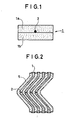
- the flexible tape made of carbon/carbon composites of the soft type (hereinafter referred to as "composite tape") according to the present invention is prepared by sticking two expanded graphite tapes 1a and 1b together, between which a carbon fiber 2 in a bundle or string is held, as shown in Fig. 1.
- the position of the carbon fiber 2 is, for example, the center in the cross direction of the expanded graphite tapes 1a and 1b, when the bending section of a metal strip having a V-shaped in cross section is located at the center in the cross direction of said metal strip.
- the carbon fiber 2 is caused to locate in the bending section of the composite tape 1 when the metal strip 5 having a V-shaped in cross section and the composite tape 1 are piled up and wound.
- the cross section of the metal strip is made W-shaped or the like so that the metal strip may have a plurality of bending sections.
- the composite tape may be prepared similarly in such a way that a bundle- or string-shaped carbon fiber is caused to locate in each of a plurality of the bending sections of said composite tape formed when the metal strip and the tape are piled up and wound.
- the width of the composite tape which is selected in acco dance with the size of a desired spiral wound gasket. It is however necessary for the composite tape to have such a width that its both edges in the cross direction protrude from the edges of the metal strip when the metal strip and the tape are piled up and wound.
- the thickness of the composite tape may suitably be chosen depending on the use purpose of a desired spiral wound gasket. Further, as seen in Fig. 1, the position of the carbon fiber 2 in the thickness direction of the composite tape 1 is determined by the selection of the thickness of the expanded graphite tapes 1a and 1b. Here, it is desirable to place the carbon fiber 2 in a position between one-thirds and two-thirds of the thcikness of the composite tape 1.
- the composite tape 1 is obtained by sticking the expanded graphite tapes 1a and 1b together in such a way that the carbon fiber 2 is held in between.
- the sticking is carried out by applying a vanish made of a thermosetting resin such as phenol resin and furan resin on either one or both of the surfaces of the expanded graphite tapes 1a and 1b to stick the two surfaces together, the surfaces holding or being in contact with the carbon fiber 2, and then causing the vanish to cure with heat.
- the resin is carbonized by treating the combined tapes at a higher temperature (e.g. 1,000°C).
- Thermoplastic resins may also be used as the adhesive resin depending on purposes.
- the composite tape 1 may also be prepared not by way of the sticking but by incorporating a carbon fiber into an expanded graphite tape while the tape is being molded.
- Preferred metal strips will have high strengths and superb weldabilities. Hoop materials made of stainless steel are generally used.
- the metal strip is smaller in width than the expanded graphite tapes 1a and 1b and has, for example, a V- or W-shaped in cross section.
- the spiral wound gasket is fabricated by winding circularly and spirally the metal strip with the composite tape piled up and fixing both longitudinal ends of the metal strip by spot welding or the like.
- the composite tape and the metal strip are so wound that the tape protrudes from the edges of the metal strip on the both sides in the cross direction of the spiral wound gasket.
- a metal strip (0.2 mm in thickness and 5.8 mm in width when extended) 5 which is a stainless steel hoop material molded in a V-shape in advance, and the foregoing composite tape 1 were wound circularly and spirally while being piled up in such a way that the V-sahped bending section of the metal strip 5 was coincident in position with the carbon fiber 2 in the composite tape 1.
- a spiral wound gasket with an inner diameter of 90 mm, an outer diameter of 110 mm and a height of 4.5 mm was obtained.
- the composite tape 1, i.e. the filler was allowed to protrude by about 0.2 mm from the both edges in the cross direction of the metal strip 5.
- the metal strip 5 was wound solely 6 times at each of the start and end of the winding, and the both ends in the longitudinal direction of the metal strip 5 were fixed respectively by spot welding.
- a spiral wound gasket was obtained in the same manner as in Example 1, except for the use of an asbestos tape (0.4 mm in thickness and 6.2 mm in width) in place of the composite tape 1 described in Example 1 as the filler.
- a spiral wound gasket with the same shape and size as that obtained in Comparative Example 1 was fabricated in the same manner as in Comparative Example 1, except for the use of an expanded graphite tape (HGP-207, manufactured by Hitachi Chemical Co., Ltd.; 400 g/m2 in weight per unit area, 0.4 mm in thickness and 6.2 mm in width) in place of the asbestos tape described in Comparative Example 1 as the filler.
- HGP-207 expanded graphite tape
- a spiral wound gasket was obtained in the same manner as in Example 1, except for the alteration of the number of filaments in the carbon fiber to 3,000.
- Example 1 The two expanded graphite tapes sticked together in the same manner as in Example 1 to obtain a composite tape having the same size as that used in Example 1.
- a spiral wound gasket was then prepared in the same manner as in Example 1 by using the composite tape and the same metal strip as employed in Example 1.
- a spiral wound gasket was fabricated in the same manner as in Example 1 except that the front (top) and the back (bottom) of the composite tape given in Example 3 were reversed (turned upside down).
- Example 1 The composite tape given in Example 1 was burned at a temperature of 800°C in an atmosphere of nitrogen to carbonize the phenolic resin used as the binder. Using the resulting composite tape, a spiral wound gasket was prepared in the same manner as in Example 1.
- the sealing performance was determined as He permeability k(cm2/sec) in accordance with the following equation using the data obtained by placing a jig sealed hermetically with a spiral wound gasket in a vacuum apparatus to evacuate the outer periphery of the spiral wound gasket, sealing helium (He) gas in the jig at 1 atmosphere and measuring the volume of the helium gas permeating from the inner periphery to the outer periphery of the spiral wound gasket.
- He helium
- r o outer diameter of spiral wound gasket (cm)
- r i inner diameter of spiral wound gasket (cm)
- F flow rate of helium (mole/sec)
- R gas constant (cm3 ⁇ atm/K ⁇ mole)
- T absolute temperature (K)
- L height of spiral wound gasket (cm)
- P gas pressure difference between inner and outer peripheries (atm)
- the tensile strength of the composite tapes in Examples 1 through 5 is far higher than that of the abestos tape in Comparative Example 1 or that of the expanded graphite tape in Comparative Example 2, and the spiral wound gaskets in Examples 1 through 5 have lower He permeabilities K than those in Comparative Example 1 and Comparative Example 2 and hence are superior in sealing performance.
Landscapes
- Engineering & Computer Science (AREA)
- General Engineering & Computer Science (AREA)
- Mechanical Engineering (AREA)
- Gasket Seals (AREA)
Applications Claiming Priority (2)
| Application Number | Priority Date | Filing Date | Title |
|---|---|---|---|
| JP1087031A JPH02266164A (ja) | 1989-04-07 | 1989-04-07 | 渦巻ガスケツト及びその製造法 |
| JP87031/89 | 1989-04-07 |
Publications (3)
| Publication Number | Publication Date |
|---|---|
| EP0391069A2 true EP0391069A2 (fr) | 1990-10-10 |
| EP0391069A3 EP0391069A3 (fr) | 1991-08-14 |
| EP0391069B1 EP0391069B1 (fr) | 1996-05-29 |
Family
ID=13903586
Family Applications (1)
| Application Number | Title | Priority Date | Filing Date |
|---|---|---|---|
| EP90103976A Expired - Lifetime EP0391069B1 (fr) | 1989-04-07 | 1990-03-01 | Joint en spirale et son procédé de fabrication |
Country Status (4)
| Country | Link |
|---|---|
| US (1) | US5082296A (fr) |
| EP (1) | EP0391069B1 (fr) |
| JP (1) | JPH02266164A (fr) |
| DE (1) | DE69027148T2 (fr) |
Cited By (6)
| Publication number | Priority date | Publication date | Assignee | Title |
|---|---|---|---|---|
| DE9113953U1 (de) * | 1991-11-09 | 1992-01-16 | Kempchen & Co. GmbH, 4200 Oberhausen | Dichtungsanordnung für eine Flanschdichtung bei einer Rohrleitung |
| WO1993007407A1 (fr) * | 1991-09-30 | 1993-04-15 | Flexitallic Limited | Ameliorations se rapportant a des joints d'etancheite |
| EP0571101A1 (fr) * | 1992-05-18 | 1993-11-24 | Toyota Jidosha Kabushiki Kaisha | Joint à enroulement spiralé pour échaffement automobile |
| WO1995032376A1 (fr) * | 1994-05-23 | 1995-11-30 | Keystone Vanessa S.R.L. | Procede de fabrication d'un joint annulaire a obturation frontale et joint ainsi obtenu |
| EP0992719A1 (fr) * | 1997-05-07 | 2000-04-12 | Nippon Pillar Packing Co. Ltd. | MATERIAU DE REMPLISSAGE pour Garniture spiralée et garniture spiraleé |
| CN103016732A (zh) * | 2012-12-31 | 2013-04-03 | 自贡鑫剑密封科技有限公司 | H型金属复合垫片 |
Families Citing this family (22)
| Publication number | Priority date | Publication date | Assignee | Title |
|---|---|---|---|---|
| US5370405A (en) * | 1991-08-30 | 1994-12-06 | Nippon Pillar Packing Co., Ltd. | Packing |
| GB9017173D0 (en) * | 1990-08-06 | 1990-09-19 | Specialist Sealing Ltd | Static seal |
| GB9312174D0 (en) * | 1993-06-12 | 1993-07-28 | Flexitallic Ltd | Gasket |
| GB2278893B (en) * | 1993-06-12 | 1997-01-29 | Flexitallic Ltd | Gasket |
| DE29609769U1 (de) * | 1996-06-01 | 1996-08-29 | Kempchen & Co. Gmbh, 46049 Oberhausen | Dichtungsanordnung zwischen einer Flanschverbindung |
| US6025018A (en) * | 1997-03-25 | 2000-02-15 | Metex Mfg. Corporation | Method and apparatus for making wire mesh preform |
| JP2882602B1 (ja) | 1998-03-17 | 1999-04-12 | 日本ピラー工業株式会社 | うず巻形ガスケットの製造方法及び製造装置 |
| US6055806A (en) * | 1998-05-08 | 2000-05-02 | Caterpillar Inc. | Exhaust manifold seals to eliminate oil slobber |
| CH710862B1 (de) | 1999-11-26 | 2016-09-15 | Imerys Graphite & Carbon Switzerland Sa | Verfahren zur Herstellung von Graphitpulvern mit erhöhter Schüttdichte. |
| CN1278439C (zh) * | 2001-10-08 | 2006-10-04 | 蒂米卡尔股份公司 | 电化学电池 |
| US6708983B2 (en) | 2001-11-01 | 2004-03-23 | Federal-Mogul World Wide, Inc. | Spiral wound cylinder head gasket |
| WO2005089275A2 (fr) * | 2004-03-17 | 2005-09-29 | Garlock Sealing Technologies Llc | Maintien empile d'enroulements spirales destines a des joints d'etancheite statiques spirales |
| JP4376230B2 (ja) * | 2006-01-10 | 2009-12-02 | 日本ピラー工業株式会社 | うず巻ガスケット |
| US9285062B2 (en) * | 2007-11-02 | 2016-03-15 | Lamons Gasket Company | Spiral-wound gasket |
| GB0903462D0 (en) * | 2009-03-02 | 2009-04-08 | Flexitallic Invest Inc | Sealing arrangements |
| US8505922B2 (en) * | 2010-08-16 | 2013-08-13 | Federal-Mogul Corporation | Bi-metal spiral wound gasket |
| EP2871391B1 (fr) * | 2012-07-06 | 2017-10-18 | Kabushiki Kaisha Toshiba | Joint spiralé |
| US9239114B2 (en) * | 2012-11-05 | 2016-01-19 | Parker-Hannifin Corporation | Compressable sealing ring assembly |
| JP6815288B2 (ja) * | 2017-07-06 | 2021-01-20 | 日本ピラー工業株式会社 | うず巻形ガスケット |
| KR102210103B1 (ko) * | 2019-06-21 | 2021-02-02 | 동서산업주식회사 | 금속 시일 및 그 제조방법 |
| KR20210048716A (ko) * | 2019-10-24 | 2021-05-04 | 주식회사 국일인토트 | 가스켓 |
| WO2024219993A1 (fr) * | 2023-04-17 | 2024-10-24 | Акционерное Общество Научно-Производственное Объединение "Унихимтек" | Insert à enroulement spirale et procédé de fabrication |
Family Cites Families (20)
| Publication number | Priority date | Publication date | Assignee | Title |
|---|---|---|---|---|
| US622889A (en) * | 1899-04-11 | Sheet material for packing | ||
| US1370234A (en) * | 1919-09-30 | 1921-03-01 | George W Stewart | Sheet-packing |
| US1747998A (en) * | 1927-01-14 | 1930-02-18 | Durametallic Corp | Packing and method of making the same |
| US1987120A (en) * | 1930-02-05 | 1935-01-08 | Dorin Corp | Packing |
| US1942703A (en) * | 1931-08-14 | 1934-01-09 | Garlock Packing Co | Gasket |
| US2799524A (en) * | 1953-09-18 | 1957-07-16 | Zagorski Johann | Wound flange packing rings for tubing, cylinders, etc. |
| FR1095570A (fr) * | 1953-12-11 | 1955-06-03 | Joint Francais | Joint métalloplastique à support et garniture en couches alternées |
| US2882083A (en) * | 1954-04-30 | 1959-04-14 | Johns Manville | Spirally wound gasket |
| US2827320A (en) * | 1955-11-30 | 1958-03-18 | Gen Electric | Seal |
| US3365203A (en) * | 1965-07-26 | 1968-01-23 | Gen Motors Corp | Rolling type diaphragm type seal including oriented reinforcement |
| US3905090A (en) * | 1972-06-22 | 1975-09-16 | Johns Manville | Method of making spiral wound gaskets |
| US4180211A (en) * | 1974-05-30 | 1979-12-25 | Versar, Inc. | High temperature compressible support and gasket material |
| US4006881A (en) * | 1974-12-09 | 1977-02-08 | Gachot S.A. | Fluid-tight packing for closure devices and devices fitted with said packing |
| CH600206A5 (fr) * | 1976-05-18 | 1978-06-15 | Meister H & Co | |
| US4127277A (en) * | 1976-09-24 | 1978-11-28 | Lamons Metal Gasket Company | Spiral wound gasket assembly and method |
| US4190257A (en) * | 1978-02-01 | 1980-02-26 | Union Carbide Corporation | Packing ring containing flexible graphite |
| JPS56101253A (en) * | 1980-01-17 | 1981-08-13 | Toshiba Corp | Programmable controller |
| GB2120135A (en) * | 1982-05-18 | 1983-11-30 | Flexitallic Ltd | Forming spiral wound gaskets |
| US4673187A (en) * | 1985-07-09 | 1987-06-16 | Fluorocarbon Company | Bimetallic spiral wound gasket |
| US4941669A (en) * | 1988-01-24 | 1990-07-17 | Honda Giken Kogyo Kabushiki Kaisha | Fiber-reinforced piston ring for internal combustion engine |
-
1989
- 1989-04-07 JP JP1087031A patent/JPH02266164A/ja not_active Expired - Lifetime
-
1990
- 1990-02-27 US US07/485,427 patent/US5082296A/en not_active Expired - Lifetime
- 1990-03-01 EP EP90103976A patent/EP0391069B1/fr not_active Expired - Lifetime
- 1990-03-01 DE DE69027148T patent/DE69027148T2/de not_active Expired - Lifetime
Cited By (7)
| Publication number | Priority date | Publication date | Assignee | Title |
|---|---|---|---|---|
| WO1993007407A1 (fr) * | 1991-09-30 | 1993-04-15 | Flexitallic Limited | Ameliorations se rapportant a des joints d'etancheite |
| US5275423A (en) * | 1991-09-30 | 1994-01-04 | Flexitallic Inc. | Spiral wound gasket |
| DE9113953U1 (de) * | 1991-11-09 | 1992-01-16 | Kempchen & Co. GmbH, 4200 Oberhausen | Dichtungsanordnung für eine Flanschdichtung bei einer Rohrleitung |
| EP0571101A1 (fr) * | 1992-05-18 | 1993-11-24 | Toyota Jidosha Kabushiki Kaisha | Joint à enroulement spiralé pour échaffement automobile |
| WO1995032376A1 (fr) * | 1994-05-23 | 1995-11-30 | Keystone Vanessa S.R.L. | Procede de fabrication d'un joint annulaire a obturation frontale et joint ainsi obtenu |
| EP0992719A1 (fr) * | 1997-05-07 | 2000-04-12 | Nippon Pillar Packing Co. Ltd. | MATERIAU DE REMPLISSAGE pour Garniture spiralée et garniture spiraleé |
| CN103016732A (zh) * | 2012-12-31 | 2013-04-03 | 自贡鑫剑密封科技有限公司 | H型金属复合垫片 |
Also Published As
| Publication number | Publication date |
|---|---|
| US5082296A (en) | 1992-01-21 |
| DE69027148T2 (de) | 1997-01-23 |
| DE69027148D1 (de) | 1996-07-04 |
| JPH02266164A (ja) | 1990-10-30 |
| EP0391069A3 (fr) | 1991-08-14 |
| EP0391069B1 (fr) | 1996-05-29 |
Similar Documents
| Publication | Publication Date | Title |
|---|---|---|
| EP0391069A2 (fr) | Joint en spirale et son procédé de fabrication | |
| EP0440116B1 (fr) | Stratifié flexible en graphite et méthode pour sa fabrication | |
| US4234638A (en) | Composite graphite sheets | |
| US20060220320A1 (en) | Thermal insulation structures comprising layers of expanded graphite particles compressed to different densities and thermal insulation elements made from these structures | |
| US4729910A (en) | Reinforced flexible graphite sheet | |
| CA2161547A1 (fr) | Joint renforce pour structures en materiau composite et procede associe | |
| JPS5547335A (en) | Manufacturing method of fiber reinforced metal based composite material | |
| JP2705834B2 (ja) | ガスケット製品及びその製造方法 | |
| ATE189637T1 (de) | Verfahren zur herstellung eines hochporösen nicht verdampfbaren gettermaterials und damit hergestelltes material | |
| EP0992719B1 (fr) | MATERIAU DE REMPLISSAGE pour Garniture spiralée et garniture spiraleé | |
| CA1282943C (fr) | Produit ceramique arme de fibres, et sa production | |
| EP0388481B1 (fr) | Joint en graphite expansé et son matériau | |
| US6472059B2 (en) | Combination continuous woven-fiber and discontinuous ceramic-fiber structure | |
| EP0449268B1 (fr) | Matériau pour joint d'étanchéité de graphite expansé | |
| JPS62292429A (ja) | 熱絶縁材 | |
| JP3389522B2 (ja) | うず巻形ガスケット用フィラー材およびそのフィラー材を使用したうず巻形ガスケット | |
| ES8701048A1 (es) | Un procedimiento de fabricar un material de junta de estan- queidad. | |
| RU2079754C1 (ru) | Плоская многослойная прокладка | |
| JPH05148472A (ja) | 高密度密封材及び高密度密封材の製法、並びに高密度密封材製造装置 | |
| EP0388766B1 (fr) | Matériau d'étoupage et méthode pour le fabriquer | |
| JP2678291B2 (ja) | 板状炭素複合材料及びその製造法 | |
| JPH09187865A (ja) | フッ素樹脂積層パイプ及びその製造方法 | |
| JPS6319304Y2 (fr) | ||
| JPS62105910A (ja) | 積層炭素材料 | |
| ATE111791T1 (de) | Beschwerungselement und verfahren zu dessen herstellung. |
Legal Events
| Date | Code | Title | Description |
|---|---|---|---|
| PUAI | Public reference made under article 153(3) epc to a published international application that has entered the european phase |
Free format text: ORIGINAL CODE: 0009012 |
|
| 17P | Request for examination filed |
Effective date: 19900417 |
|
| AK | Designated contracting states |
Kind code of ref document: A2 Designated state(s): DE FR GB |
|
| PUAL | Search report despatched |
Free format text: ORIGINAL CODE: 0009013 |
|
| RHK1 | Main classification (correction) |
Ipc: F16J 15/12 |
|
| AK | Designated contracting states |
Kind code of ref document: A3 Designated state(s): DE FR GB |
|
| 17Q | First examination report despatched |
Effective date: 19931029 |
|
| GRAH | Despatch of communication of intention to grant a patent |
Free format text: ORIGINAL CODE: EPIDOS IGRA |
|
| GRAA | (expected) grant |
Free format text: ORIGINAL CODE: 0009210 |
|
| AK | Designated contracting states |
Kind code of ref document: B1 Designated state(s): DE FR GB |
|
| REF | Corresponds to: |
Ref document number: 69027148 Country of ref document: DE Date of ref document: 19960704 |
|
| ET | Fr: translation filed | ||
| PLBE | No opposition filed within time limit |
Free format text: ORIGINAL CODE: 0009261 |
|
| STAA | Information on the status of an ep patent application or granted ep patent |
Free format text: STATUS: NO OPPOSITION FILED WITHIN TIME LIMIT |
|
| 26N | No opposition filed | ||
| REG | Reference to a national code |
Ref country code: GB Ref legal event code: IF02 |
|
| PGFP | Annual fee paid to national office [announced via postgrant information from national office to epo] |
Ref country code: DE Payment date: 20090527 Year of fee payment: 20 |
|
| PGFP | Annual fee paid to national office [announced via postgrant information from national office to epo] |
Ref country code: FR Payment date: 20090223 Year of fee payment: 20 |
|
| PGFP | Annual fee paid to national office [announced via postgrant information from national office to epo] |
Ref country code: GB Payment date: 20090427 Year of fee payment: 20 |
|
| REG | Reference to a national code |
Ref country code: GB Ref legal event code: PE20 Expiry date: 20100228 |
|
| PG25 | Lapsed in a contracting state [announced via postgrant information from national office to epo] |
Ref country code: GB Free format text: LAPSE BECAUSE OF EXPIRATION OF PROTECTION Effective date: 20100228 |
|
| PG25 | Lapsed in a contracting state [announced via postgrant information from national office to epo] |
Ref country code: DE Free format text: LAPSE BECAUSE OF EXPIRATION OF PROTECTION Effective date: 20100301 |