EP0390141A2 - Verfahren und Vorrichtung zur Verbrennung von flüssigem Brennstoff - Google Patents
Verfahren und Vorrichtung zur Verbrennung von flüssigem Brennstoff Download PDFInfo
- Publication number
- EP0390141A2 EP0390141A2 EP90106015A EP90106015A EP0390141A2 EP 0390141 A2 EP0390141 A2 EP 0390141A2 EP 90106015 A EP90106015 A EP 90106015A EP 90106015 A EP90106015 A EP 90106015A EP 0390141 A2 EP0390141 A2 EP 0390141A2
- Authority
- EP
- European Patent Office
- Prior art keywords
- combustion
- fuel
- liquid fuel
- air
- burning
- Prior art date
- Legal status (The legal status is an assumption and is not a legal conclusion. Google has not performed a legal analysis and makes no representation as to the accuracy of the status listed.)
- Granted
Links
Images


Classifications
-
- F—MECHANICAL ENGINEERING; LIGHTING; HEATING; WEAPONS; BLASTING
- F23—COMBUSTION APPARATUS; COMBUSTION PROCESSES
- F23D—BURNERS
- F23D5/00—Burners in which liquid fuel evaporates in the combustion space, with or without chemical conversion of evaporated fuel
-
- F—MECHANICAL ENGINEERING; LIGHTING; HEATING; WEAPONS; BLASTING
- F23—COMBUSTION APPARATUS; COMBUSTION PROCESSES
- F23D—BURNERS
- F23D5/00—Burners in which liquid fuel evaporates in the combustion space, with or without chemical conversion of evaporated fuel
- F23D5/12—Details
- F23D5/14—Maintaining predetermined amount of fuel in evaporator
Definitions
- the present invention relates to a method and apparatus for burning liquid fuel in a wide range of applications from household oil stoves up to industrial furnaces.
- a heretofore known practice is to burn liquid fuel either directly gasified or as finely vaporized by an atomizer.
- the former method of burning the directly gasified fuel is widely used in general household oil stoves, typical of which are a pot type (JU-A-No. 35713/1983), a wick type (JP-A-Nos. 203307/1983 and 64134/1985) and a vaporization type (JIS 3030).
- the pot type employs a burner bowl on which fuel is vaporized before being burned and is equipped with a combination of vaporization and combustion units.
- Oil burners generally in use are adapted to burn fuel by means of a rotary burner, jet burner (vaporization spray, air spray and mechanical spray), special burner (gun-type high-pressure spray and low pressure spray) or the like.
- a kind of ignition device for igniting liquid fuel in the form of foam JP-B-No. 42018/1974, JP-A-No. 38368/1972.
- the flame in an oil stove has to be extinguishable as quickly as possible (e.g., according to JIS, the flame in the oil stove has to be extinguished within 10 seconds after an earthquake occurs or when it is tipped over by accident).
- the offensive smell generated when it is turned off therefore tends to becomes stronger.
- spray combustion lacks uniformity, because oil drops insufficiently vaporized and mixed reach the front face of the flame before being enclosed in diffusion flame. The flame tends to become nonuniform, causing partial overheating to parts being heated.
- An object of the present invention is to provide a combustion method comprising the steps of supplying liquid fuel to the outside of a porous element to instantly burn the liquid fuel in the form of a foam with air supplied to the porous element to greatly increase the surface area of the vaporized fuel and simultaneously promote the combustive reaction.
- Another object of the present invention is to provide a combustion method capable of readily igniting and burning liquid fuel in the form of bubbles without using a wick and which is capable of easily controlling the amount of combustion.
- the present invention is intended to provide a method of forming liquid fuel into bubbles and continuously burning it in a combustion chamber in order to adjust the amount of combustion, to prevent the generation of offensive smells at the time of ignition and after the flame is extinguished and to realize flame uniformity.
- the present invention is particularly effective when it is applied to oil stoves.
- Bubbles is used in the present specification as a general term meaning both dispersed bubbles consisting of numerous bubbles of air or oxygen which have floated to the surface of a liquid and foam consisting of bubbles separated by thin liquid films.
- the method of burning liquid fuel in the form of foam or dispersed bubbles is characterized in that the contact area of the fuel with air can be increased hundreds of times in a condition different from heretofore. Moreover, it has the effects of increasing the evaporation and diffusion coefficients, reducing the partial vapor pressure of the fuel on the boundary between air and liquid, and further promoting the reaction between evaporation and combustion.
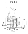
- FIG. 1 is a vertical sectional view of an embodiment of the present invention.
- numeral 4 denotes a porous element (hereinafter called the air feeder) which functions as a fuel foamer and 26 an evaporating dish.
- Fuel is supplied from a fuel tank 19 via a pump 25 and a supply pipe 6 to a combustion chamber 1.
- the evaporating dish 26 and the air feeder are disposed under the combustion chamber 1.
- the combustion chamber 1 is provided with a closed jacket 27 for supplying combustion air.
- the positional relationship between the air feeder 4 and the evaporating dish 26 is such that the surface of the air feeder 4 and the lower end of the evaporating dish 26 may be at the same level or different in level.
- Porous element' is used herein as a general term meaning capillaries, cloth, particle layer, porous plate having holes, sinter metal, porous ceramic or the like.
- Liquid fuel is supplied to the evaporating dish 26 on the air feeder 4.
- the fuel kerosine, light oil or the like
- the fuel in the form of foam is then ignited by an igniting heater 28 and burned.
- the amount of combustion air required for complete combustion is separately supplied from a supply pipe 8 via the closed jacket 27 to cause continuous combustion.
- Numeral 14 denotes a flame.
- the fuel is supplied via the fuel supply pipe 6 and the generation of bubbles is increased by increasing the amount of air supplied from the air supply pipe 7.
- the amount of combustion can readily be increased by increasing the amount of air supplied from the combustion air pipe 8. As the amount of gas (air) supplied from the air supply pipe 7 is increased while the amount of fuel thus supplied is kept constant, the flame grows.
- liquid fuel is formed into bubbles before being ignited according to the present invention, it can easily be ignited simply by directly contacting an ignition source with the bubbled fuel.
- the bubbling expansion ratio (apparent volume/liquid fuel volume in the mixture of liquid and gas) of the bubbles obtained only from liquid fuel such as kerosine, light oil or the like normally ranges from approximately 5 to 50 times.
- the air expansion ratio required for complete combustion is approximately 9,000 times and the amount of air within the bubbles is far too small.
- the amount of air supplied from the combustion air pipe 8 should preferably be in the range of approximately 60 - 250% of the theoretical amount of combustion air.
- a stable formation of bubbles is required particularly during a transition period up to the time that stable combustion is obtained after the flame is ignited.
- 250% as the upper limit indicates a minimum flow rate of air from the combustion air pipe 8 when the amount of air from the air supply pipe 7 is set at the minimum value required for the stable formation of foam.
- An air feeder 4 for generating foam and dispersed bubbles of liquid fuel and a fuel supply pipe 6 were provided under a combustion chamber 1 and a air supply pipe 7 was connected to the air feeder 4 to form a foam generating zone a .
- a number of combustion air inlet openings 9 were provided in the upper side portion of the combustion chamber to form a combustion zone b where liquid fuel was burned.
- the air feeder 4 comprised a porous element having a foaming function, the bottom being pot-shaped.
- the combustion state at this time was such that the mixture of the fuel with the combustion air was promoted in a flame stabilizer 30 to the extent that a blue-white flame extended upward in the flame stabilizer 30, i.e., complete combustion was realized.
- the time required for the flame to be produced in the upper portion of the flame stabilizer 30 after ignition was as short as 20 seconds.
- the amount of fuel being supplied was increased up to 1.0 l/H, whereas the amount of combustion air was set at 160 l/min.
- the flame grew to become blue-white instantly on the flame port plate and stable combustion was continued.
- the stabilizer is constituted with a cylindrical skeleton 33 fitted to the underside of a baffle plate 32 having holes bored therein.
- the stabilizer is set coaxially with the porous element.
- porous plate with holes having a predetermined diameter was used as the air feeder 4 in this experiment, use can also be made of capillaries, a cloth, a particle layer or an air feeding method in combination therewith to generate bubbles.
- the material and shape of such a porous element are not limited to those described in the embodiment shown.
- numeral 1 denotes a combustion chamber, 2 a foam gathering cylinder, 3 an orifice, and 4 an air feeder.
- a fuel supply pipe 6 for supplying liquid fuel is connected to the underside of the foam gathering cylinder 2.
- a foaming air supply pipe 7 is connected to the lower portion of the air feeder 4 so that gas such as air can be supplied from the outside.
- Numeral 8 denotes an air supply pipe, and 9 secondary air supply holes.
- the orifice is located in the lower portion of the combustion chamber 1, which is a cylindrical or polygonal body and provided with a number of combustion air inlet openings.
- the bubbled fuel is introduced from the foam gathering cylinder 2 into the orifice before being supplied to the combustion chamber 1.
- the air contained in the foam and what is supplied from the air inlet openings 9 make the fuel readily burn with its flame formed thereabove.
- Figure 4 shows a combustion state of liquid fuel according to the present invention.
- Reference character h denotes the height of the foam, whereas numeral 11 denotes fuel, 12 foaming air, and 13 combustion air.
- the air feeder 4 is made of sintered metal, porous ceramic or the like. The liquid fuel supplied to the foam gathering cylinder 2 is caused to readily foam by the fine air current jetted out of the air feeder 4.
- the present invention is intended to provide a method and apparatus for freely controlling the amount of combustion of fuel in the form of bubbles. More specifically, the method is intended to control the amount of combustion by changing the level of the liquid fuel on the air feeder installed inside the foam gathering cylinder in the apparatus for burning the liquid fuel in the form of bubbles.
- the amount of combustion increases as the fuel rising through the foam gathering cylinder 2 and supplied to the combustion chamber 1 increases to cause an increase in the thickness of the liquid film of foam even though the amount of air supplied from the foaming air supply pipe 7 is kept constant.
- Figure 5 shows an apparatus for controlling the combustion of liquid fuel by vertically moving a small tank having a built-in float to change the liquid level in the foam gathering cylinder.
- a liquid level regulating tank 16 is connected via a flexible hose 14 to a fuel supply pipe 6.
- the liquid level regulating tank 16 has a built-in float 17 and is provided with a liquid reservoir 15 and an air vent hole 18, whereas a fuel hose 20 from a fuel tank 19 is connected to the liquid level regulating tank 16, the fuel hose being fitted with a fuel flow rate regulating valve 21.
- the liquid regulating tank 16 functions to shut a needle valve 23 provided on the surface of the float by making use of the buoyant force acting on the float 17 and so suspend the supply of fuel from the fuel tank.
- the liquid level regulating tank 16 and the fuel supply pipe 6 are coupled via the flexible hose 14 and they communicate with each other.
- a liquid level regulating tank elevator 22 is used to raise the position of the liquid level regulating tank.
- the position of the liquid level regulating tank is lowered until the fuel level in the foam gathering cylinder is located below the lowermost portion of the hole of the air feeder to move fuel to the liquid level regulating tank in an instant.
- the fuel that has been caused to flow in is temporarily stored in the liquid reservoir 15.
- the liquid level regulating tank is raised by the elevator 22 up to the liquid level z corresponding to the required amount of foam to be generated.
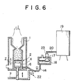
- Figure 6 shows another apparatus embodying the present invention wherein combustion is controlled by elevating a air feeder 4 to change the liquid level of liquid fuel on the air feeder.
- a foaming air supply pipe 7 is fitted to the air feeder 4 provided in a foam gathering cylinder 2 coupled to the lower portion of a combustion chamber 1.
- the air supply pipe 7 is equipped with an elevator 22 for vertically moving the air feeder and a desired liquid level can be set manually or by the operation of a motor.
- a fuel supply pipe 6 is fitted to the lower portion of the foam gathering cylinder 2 and also coupled to a liquid level regulating tank 16.
- the liquid level regulating tank 16 has a built-in float 17, whereas fuel from a fuel tank 19 is led by a fuel hose 20, whereby fuel is supplied when a needle valve 23 opens/shuts as the float 17 moves vertically.
- the liquid level regulating tank 16 is designed to keep the liquid level in the air feeder 4 at a predetermined height at all times during combustion and to continuously replenish the fuel to the extent that the liquid level in the air feeder lowers because of combustion. Since the liquid level regulating tank 16 and the air feeder 4 are coupled together by means of a fuel coupling pipe (flexible hose) 14, the liquid levels in both of them are set equal.
- the air feeder 4 When the amount of combustion in the present state is decrease in this apparatus, the air feeder 4 is raised from the present position. The distance between the air feeder 4 and the liquid fuel level within the foam gathering cylinder 2 is shortened, i. e., the liquid level z is lowered and the amount of bubbles to be generated is decreased. The amount of combustion is also decreased.
- the whole air feeder 4 is raised from the liquid fuel area in the foam gathering cylinder to be exposed above the liquid fuel and stop the supply of gas, while the supply of gas to the air feeder 4 is continued. As shown in Figure 7, the air feeder 4 is raised until it contacts the orifice 3 at the entrance of the combustion chamber and the flame is quickly extinguished.
- foaming gas is supplied to the porous element as it is lowered and immersed in the liquid fuel.
- the amount of foam 5 generated in the foam gathering cylinder 2 i.e., the amount of liquid fuel for use in forming bubbles to be supplied to the combustion chamber 1 is increased.
- the amount of combustion is thus increased.
- the flow rate of foaming air 12 is decreased, the amount of foam 5 generated is decreased. The amount of combustion is therefore decreased.
- the characteristics of the amount of combustion shown in Figure 8 are utilized to facilitate the control of two factors: the liquid level and the flow rate of gas.
- the amount of combustion was 2.0 l/H in terms of the consumption of kerosine while stable combustion was continued.
- the present invention is not limited to the method of controlling these factors.
Landscapes
- Engineering & Computer Science (AREA)
- Chemical & Material Sciences (AREA)
- Combustion & Propulsion (AREA)
- Mechanical Engineering (AREA)
- General Engineering & Computer Science (AREA)
- Evaporation-Type Combustion Burners (AREA)
- Wick-Type Burners And Burners With Porous Materials (AREA)
- Spray-Type Burners (AREA)
Applications Claiming Priority (4)
| Application Number | Priority Date | Filing Date | Title |
|---|---|---|---|
| JP81238/89 | 1989-03-31 | ||
| JP1081238A JPH02259312A (ja) | 1989-03-31 | 1989-03-31 | 液体燃料の燃焼制御方法および装置 |
| JP1081237A JPH0668364B2 (ja) | 1989-03-31 | 1989-03-31 | 液体燃料の燃焼装置 |
| JP81237/89 | 1989-03-31 |
Publications (3)
| Publication Number | Publication Date |
|---|---|
| EP0390141A2 true EP0390141A2 (de) | 1990-10-03 |
| EP0390141A3 EP0390141A3 (de) | 1991-07-03 |
| EP0390141B1 EP0390141B1 (de) | 1996-06-12 |
Family
ID=26422271
Family Applications (1)
| Application Number | Title | Priority Date | Filing Date |
|---|---|---|---|
| EP90106015A Expired - Lifetime EP0390141B1 (de) | 1989-03-31 | 1990-03-29 | Verfahren und Vorrichtung zur Verbrennung von flüssigem Brennstoff |
Country Status (4)
| Country | Link |
|---|---|
| US (1) | US5066219A (de) |
| EP (1) | EP0390141B1 (de) |
| KR (1) | KR950012777B1 (de) |
| DE (1) | DE69027360T2 (de) |
Cited By (5)
| Publication number | Priority date | Publication date | Assignee | Title |
|---|---|---|---|---|
| FR2927150A1 (fr) * | 2008-02-04 | 2009-08-07 | Brisach Soc Par Actions Simpli | Cheminee pour combustion d'un carburant liquide avec de l'air. |
| FR2927149A1 (fr) * | 2008-02-04 | 2009-08-07 | Brisach Soc Par Actions Simpli | Cheminee pour combustion d'un carburant liquide avec de l'air. |
| WO2009101416A3 (en) * | 2008-02-12 | 2010-11-25 | Josef Hacohen | Burner operation |
| WO2011127755A1 (zh) * | 2010-04-15 | 2011-10-20 | Ng King Ching | 一种燃烧燃油减缓温室气体排放方法及无辐射式燃油燃烧器 |
| EP3211304A1 (de) * | 2016-02-25 | 2017-08-30 | Ifire Bvba | Verbesserter bioethanol-kamin |
Families Citing this family (8)
| Publication number | Priority date | Publication date | Assignee | Title |
|---|---|---|---|---|
| CA2049009C (en) * | 1990-03-20 | 1995-02-07 | Norio Anzawa | Method and apparatus for burning foamed liquid fuel |
| FR2899956B1 (fr) * | 2006-04-14 | 2008-07-25 | Thirode Grandes Cuisines Poligny | Bruleur a gaz pour four de cuisine |
| US8124289B2 (en) * | 2007-01-22 | 2012-02-28 | Rolls-Royce Fuel Cell Systems (Us) Inc. | Multistage combustor and method for starting a fuel cell system |
| CN201259252Y (zh) * | 2008-08-18 | 2009-06-17 | 何梅顺 | 一种喷气式燃气灶 |
| US8622053B2 (en) * | 2009-03-16 | 2014-01-07 | Planika Sp. Z O.O. | Burner and method of its operation |
| JP2010230257A (ja) * | 2009-03-27 | 2010-10-14 | Dainichi Co Ltd | 燃焼装置 |
| US9038576B2 (en) * | 2013-05-22 | 2015-05-26 | Plum Combustion, Inc. | Ultra low NOx burner using distributed direct fuel injection |
| US20150153066A1 (en) * | 2013-12-04 | 2015-06-04 | Victory Energy Operations. L.L.C. | Method of providing heat to a heat exchanger apparatus via a burner |
Family Cites Families (14)
| Publication number | Priority date | Publication date | Assignee | Title |
|---|---|---|---|---|
| US70117A (en) * | 1867-10-22 | post and jeptha garbabd | ||
| US1378689A (en) * | 1920-06-02 | 1921-05-17 | Larson John Andrew | Oil-burner |
| US2357587A (en) * | 1942-02-25 | 1944-09-05 | Swartzbaugh Mfg Company | Oil burner |
| US3104696A (en) * | 1961-06-22 | 1963-09-24 | Socony Mobil Oil Co Inc | Foam heating oil burner and method of combustion |
| FR1315899A (fr) * | 1961-12-14 | 1963-01-25 | Procédé et dispositif de combustion pour liquides peu volatils, ainsi que leurs applications | |
| DE1401764A1 (de) * | 1962-09-06 | 1969-04-10 | Peter Boch | OElbrenner in Verbindung mit einer Reguliervorrichtung |
| FR1485604A (fr) * | 1966-03-28 | 1967-06-23 | Perfectionnements apportés aux appareils de chauffage équipés de foyers à combustible liquide | |
| JPS4738368A (de) * | 1971-04-19 | 1972-12-04 | ||
| JPS5111372B2 (de) * | 1972-08-29 | 1976-04-10 | ||
| SU578526A1 (ru) * | 1975-11-17 | 1977-10-30 | Ивановский Энергетический Институт Имени В.И.Лен На | Способ регулировани горени топливо-воздушной смеси |
| SU666382A2 (ru) * | 1976-12-03 | 1979-06-05 | Ивановский энергетический институт им.В.И.Ленина | Барботажна горелка |
| JPS5835713A (ja) * | 1981-08-21 | 1983-03-02 | Matsushita Electric Ind Co Ltd | 垂直磁化記録用磁気ヘツド |
| JPS58203307A (ja) * | 1982-05-20 | 1983-11-26 | Matsushita Electric Ind Co Ltd | 灯芯式石油燃焼装置 |
| JPS6064134A (ja) * | 1983-09-19 | 1985-04-12 | Sanyo Electric Co Ltd | 石油スト−ブ |
-
1990
- 1990-03-27 KR KR1019900004077A patent/KR950012777B1/ko not_active Expired - Fee Related
- 1990-03-28 US US07/500,782 patent/US5066219A/en not_active Expired - Fee Related
- 1990-03-29 EP EP90106015A patent/EP0390141B1/de not_active Expired - Lifetime
- 1990-03-29 DE DE69027360T patent/DE69027360T2/de not_active Expired - Fee Related
Cited By (7)
| Publication number | Priority date | Publication date | Assignee | Title |
|---|---|---|---|---|
| FR2927150A1 (fr) * | 2008-02-04 | 2009-08-07 | Brisach Soc Par Actions Simpli | Cheminee pour combustion d'un carburant liquide avec de l'air. |
| FR2927149A1 (fr) * | 2008-02-04 | 2009-08-07 | Brisach Soc Par Actions Simpli | Cheminee pour combustion d'un carburant liquide avec de l'air. |
| WO2009098167A1 (fr) * | 2008-02-04 | 2009-08-13 | Brisach | Cheminee pour combustion d'un carburant liquide avec de l'air |
| WO2009098168A1 (fr) * | 2008-02-04 | 2009-08-13 | Brisach | Cheminee pour combustion d'un carburant liquide avec de l'air |
| WO2009101416A3 (en) * | 2008-02-12 | 2010-11-25 | Josef Hacohen | Burner operation |
| WO2011127755A1 (zh) * | 2010-04-15 | 2011-10-20 | Ng King Ching | 一种燃烧燃油减缓温室气体排放方法及无辐射式燃油燃烧器 |
| EP3211304A1 (de) * | 2016-02-25 | 2017-08-30 | Ifire Bvba | Verbesserter bioethanol-kamin |
Also Published As
| Publication number | Publication date |
|---|---|
| DE69027360T2 (de) | 1996-12-05 |
| KR950012777B1 (ko) | 1995-10-21 |
| KR900014813A (ko) | 1990-10-25 |
| DE69027360D1 (de) | 1996-07-18 |
| US5066219A (en) | 1991-11-19 |
| EP0390141A3 (de) | 1991-07-03 |
| EP0390141B1 (de) | 1996-06-12 |
Similar Documents
| Publication | Publication Date | Title |
|---|---|---|
| EP0390141A2 (de) | Verfahren und Vorrichtung zur Verbrennung von flüssigem Brennstoff | |
| CA2013302C (en) | Method and apparatus for burning liquid fuel | |
| JPS5830493B2 (ja) | 液体燃料燃焼装置 | |
| US5051090A (en) | Method and apparatus for burning liquid fuel | |
| US1601242A (en) | Oil burner | |
| GB1580383A (en) | Burner for liquid fuel | |
| US4396001A (en) | Combustion device | |
| JPH02259312A (ja) | 液体燃料の燃焼制御方法および装置 | |
| US5192203A (en) | Method and apparatus for burning foamed liquid fuel | |
| JPS6344649Y2 (de) | ||
| US4256450A (en) | Liquid fuel burner | |
| JPS6131808A (ja) | 液体燃料燃焼装置 | |
| US1188083A (en) | Apparatus for vaporizing and burning liquids. | |
| JPS6130018Y2 (de) | ||
| JPS6259309A (ja) | 燃焼装置 | |
| JPH0195205A (ja) | 液体燃料の燃焼方法 | |
| JPS6143049Y2 (de) | ||
| US1783567A (en) | Oil-burner construction | |
| JPS6246972Y2 (de) | ||
| JPH0221106A (ja) | 液体燃料の燃焼装置 | |
| JPS589069Y2 (ja) | 液体燃料燃焼装置 | |
| JPH018840Y2 (de) | ||
| JPS636607Y2 (de) | ||
| KR100249225B1 (ko) | 석유 연소기의 화염 활성화장치 | |
| JPH0531371Y2 (de) |
Legal Events
| Date | Code | Title | Description |
|---|---|---|---|
| PUAI | Public reference made under article 153(3) epc to a published international application that has entered the european phase |
Free format text: ORIGINAL CODE: 0009012 |
|
| AK | Designated contracting states |
Kind code of ref document: A2 Designated state(s): DE FR GB |
|
| 17P | Request for examination filed |
Effective date: 19901228 |
|
| PUAL | Search report despatched |
Free format text: ORIGINAL CODE: 0009013 |
|
| AK | Designated contracting states |
Kind code of ref document: A3 Designated state(s): DE FR GB |
|
| 17Q | First examination report despatched |
Effective date: 19920821 |
|
| GRAH | Despatch of communication of intention to grant a patent |
Free format text: ORIGINAL CODE: EPIDOS IGRA |
|
| GRAH | Despatch of communication of intention to grant a patent |
Free format text: ORIGINAL CODE: EPIDOS IGRA |
|
| GRAA | (expected) grant |
Free format text: ORIGINAL CODE: 0009210 |
|
| AK | Designated contracting states |
Kind code of ref document: B1 Designated state(s): DE FR GB |
|
| REF | Corresponds to: |
Ref document number: 69027360 Country of ref document: DE Date of ref document: 19960718 |
|
| ET | Fr: translation filed | ||
| PG25 | Lapsed in a contracting state [announced via postgrant information from national office to epo] |
Ref country code: GB Effective date: 19970329 |
|
| PLBE | No opposition filed within time limit |
Free format text: ORIGINAL CODE: 0009261 |
|
| STAA | Information on the status of an ep patent application or granted ep patent |
Free format text: STATUS: NO OPPOSITION FILED WITHIN TIME LIMIT |
|
| 26N | No opposition filed | ||
| GBPC | Gb: european patent ceased through non-payment of renewal fee |
Effective date: 19970329 |
|
| PG25 | Lapsed in a contracting state [announced via postgrant information from national office to epo] |
Ref country code: FR Free format text: LAPSE BECAUSE OF NON-PAYMENT OF DUE FEES Effective date: 19971128 |
|
| PG25 | Lapsed in a contracting state [announced via postgrant information from national office to epo] |
Ref country code: DE Effective date: 19971202 |
|
| REG | Reference to a national code |
Ref country code: FR Ref legal event code: ST |