EP0389716B1 - Nockenantrieb und angetriebenes Hydraulikwerkzeug - Google Patents
Nockenantrieb und angetriebenes Hydraulikwerkzeug Download PDFInfo
- Publication number
- EP0389716B1 EP0389716B1 EP89311989A EP89311989A EP0389716B1 EP 0389716 B1 EP0389716 B1 EP 0389716B1 EP 89311989 A EP89311989 A EP 89311989A EP 89311989 A EP89311989 A EP 89311989A EP 0389716 B1 EP0389716 B1 EP 0389716B1
- Authority
- EP
- European Patent Office
- Prior art keywords
- plunger
- ring
- hydraulic
- cylinder chamber
- crank mechanism
- Prior art date
- Legal status (The legal status is an assumption and is not a legal conclusion. Google has not performed a legal analysis and makes no representation as to the accuracy of the status listed.)
- Expired - Lifetime
Links
Images


Classifications
-
- F—MECHANICAL ENGINEERING; LIGHTING; HEATING; WEAPONS; BLASTING
- F16—ENGINEERING ELEMENTS AND UNITS; GENERAL MEASURES FOR PRODUCING AND MAINTAINING EFFECTIVE FUNCTIONING OF MACHINES OR INSTALLATIONS; THERMAL INSULATION IN GENERAL
- F16H—GEARING
- F16H21/00—Gearings comprising primarily only links or levers, with or without slides
- F16H21/10—Gearings comprising primarily only links or levers, with or without slides all movement being in, or parallel to, a single plane
- F16H21/16—Gearings comprising primarily only links or levers, with or without slides all movement being in, or parallel to, a single plane for interconverting rotary motion and reciprocating motion
- F16H21/18—Crank gearings; Eccentric gearings
- F16H21/36—Crank gearings; Eccentric gearings without swinging connecting-rod, e.g. with epicyclic parallel motion, slot-and-crank motion
-
- B—PERFORMING OPERATIONS; TRANSPORTING
- B25—HAND TOOLS; PORTABLE POWER-DRIVEN TOOLS; MANIPULATORS
- B25B—TOOLS OR BENCH DEVICES NOT OTHERWISE PROVIDED FOR, FOR FASTENING, CONNECTING, DISENGAGING OR HOLDING
- B25B27/00—Hand tools, specially adapted for fitting together or separating parts or objects whether or not involving some deformation, not otherwise provided for
- B25B27/14—Hand tools, specially adapted for fitting together or separating parts or objects whether or not involving some deformation, not otherwise provided for for assembling objects other than by press fit or detaching same
- B25B27/146—Clip clamping hand tools
-
- H—ELECTRICITY
- H01—ELECTRIC ELEMENTS
- H01R—ELECTRICALLY-CONDUCTIVE CONNECTIONS; STRUCTURAL ASSOCIATIONS OF A PLURALITY OF MUTUALLY-INSULATED ELECTRICAL CONNECTING ELEMENTS; COUPLING DEVICES; CURRENT COLLECTORS
- H01R43/00—Apparatus or processes specially adapted for manufacturing, assembling, maintaining, or repairing of line connectors or current collectors or for joining electric conductors
- H01R43/04—Apparatus or processes specially adapted for manufacturing, assembling, maintaining, or repairing of line connectors or current collectors or for joining electric conductors for forming connections by deformation, e.g. crimping tool
- H01R43/042—Hand tools for crimping
- H01R43/0427—Hand tools for crimping fluid actuated hand crimping tools
-
- Y—GENERAL TAGGING OF NEW TECHNOLOGICAL DEVELOPMENTS; GENERAL TAGGING OF CROSS-SECTIONAL TECHNOLOGIES SPANNING OVER SEVERAL SECTIONS OF THE IPC; TECHNICAL SUBJECTS COVERED BY FORMER USPC CROSS-REFERENCE ART COLLECTIONS [XRACs] AND DIGESTS
- Y10—TECHNICAL SUBJECTS COVERED BY FORMER USPC
- Y10T—TECHNICAL SUBJECTS COVERED BY FORMER US CLASSIFICATION
- Y10T29/00—Metal working
- Y10T29/53—Means to assemble or disassemble
- Y10T29/5313—Means to assemble electrical device
- Y10T29/532—Conductor
- Y10T29/53209—Terminal or connector
- Y10T29/53213—Assembled to wire-type conductor
- Y10T29/53222—Means comprising hand-manipulatable implement
- Y10T29/53226—Fastening by deformation
Definitions
- the present invention relates to a cam crank mechanism serving as a small and light power transmission mechanism for converting rotational movement into reciprocable movement. Further, the present invention relates to a portable motor driven hydraulic tool including a battery as a power supply source and a cam crank mechanism of the foregoing type preferably employable for a cable laying operation.
- the conventional hydraulic tool is typically constructed such that a hydraulic pump adapted to be driven by an engine or motor is placed on the ground and a pressure resistant hose extends between the hydraulic pump and a tool head carried by an operator which performs a cable laying operation at a high position.
- the hydraulic pump feeds pressurized hydraulic oil to the tool head including a stationary die and a movable die to collapse the terminal or sleeve between the two dies for connecting conductors to each other.
- a manual hydraulic tool of the type having a hydraulic pump incorporated therein has been known.
- This type of hydraulic tool is used for a cable laying operation in such a manner that an operator repeatedly actuates an actuating lever by his hand to increase hydraulic pressure of hydraulic oil and the increased hydraulic pressure displaces a movable tool member toward or away from a stationary tool member to collapse a terminal or sleeve for connecting conductors to each other.
- FR-A-640934 discloses a crank mechanism having a rotatable shaft, an eccentric shaft fixed to the rotatable shaft and a reciprocal plunger having two longitudinal ends. At one of its ends the plunger is secured to a frame engaged at an inner surface by the eccentric shaft; the inner surface is of a non-circular shape.
- DE-A-3719442 discloses a hydraulic tool having a tool head including a stationary tool member and a movable tool member.
- the hydraulic tool also has a piston for displacing the movable tool member towards and away from the stationary tool member and also has a hydraulic pressure transmitting mechanism.
- an electric power supply source which energises a motor. In turn the motor drives a mechanism for generating the hydraulic pressure.
- An object of the present invention is to provide a small and light cam crank mechanism preferably employable for a motor driven hydraulic tool which assures that rotational movement of a motor is converted into reciprocable movement with a high magnitude of output for displacing a movable tool member toward or away from a stationary tool member.
- Another object of the present invention is to provide a motor driven hydraulic tool including a cam crank mechanism of the foregoing type for performing a cable laying operation without necessity for a pressure resistant hose and a power supply cord.
- a cam crank mechanism comprising a rotational shaft, supported on the prime mover side in a casing of the cam crank mechanism, an eccentric shaft formed integrally with said rotational shaft, a cam plunger having a plunger guided in said casing for making a reciprocating motion in a chamber for generating a hydraulic pressure and a ring at one of two longitudinal ends of said plunger for converting rotation of said shaft into said reciprocating motion, said eccentric shaft being fitted in said ring so as to be freely rotatable with respect thereto to reciprocate the plunger, said ring bearing an inner surface formed in a non-circular contour so as to contact with the eccentric shaft solely in a reciprocating direction, wherein said ring is formed integrally with said plunger and said ring is moved in the reciprocating direction of said plunger without contacting the inner surface of said casing surrounding said ring.
- a hydraulic tool for use in cable laying comprising, a tool head including a stationary tool member and a movable tool member, a piston for pressing said movable tool member toward said stationary tool member, a hydraulic pump section for displacing said movable tool member toward and away from said stationary tool member, a cam crank mechanism for generating the hydraulic pressure, a driving mechanism including a motor and a speed reduction unit for driving said cam crank mechanism, said driving mechanism being arranged adjacent to said hydraulic pump section and a portable battery serving as an electric power supply source for said motor, said hydraulic pump section including a liquid tank, a first cylinder chamber communicating with said liquid tank through a liquid feed passage and a first check valve, a second cylinder chamber communicating with said first cylinder chamber through a liquid feed passage and a second check valve, and said piston inserted into said second cylinder chamber, said cam crank mechanism including an eccentric shaft formed integrally with a rotational shaft, and a cam plunger having a plunger characterised in that said
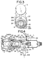
- Figs. 1 to 5 illustrate a motor driven hydraulic tool A in accordance with the present invention.
- reference numeral 1 designates a case made of plastic material
- reference numeral 2 designates a driving mechanism
- reference numeral 3 designates a hydraulic pump section
- reference numeral 4 designates a tool head.
- the case 1 includes a grip portion of which lower end has a connector 5 secured thereto.
- a plug 7 for a connection cord 6 is fitted into the connector 5.
- Opposite end of the connection code 6 is connected to a portable battery 9 via another plug 8.
- the battery 9 can be recharged by a charger 10, as required.
- a shoulder belt 11 is attached to the battery 9 so that the battery 9 can be carried by an operator with the shoulder belt 11 extending round his shoulder.
- the connector 5 is connected to a motor 15 for the drive mechanism 2 via conductors 13 and 14 and a microswitch 12.
- the microswitch 12 is turned on or off by actuating a trigger 17 under the effect of resilient force of a return spring 16.
- the drive mechanism 2 is constituted by a motor 15 and a speed reduction unit 18 operatively connected to an output shaft 15a of the motor 15.
- the speed reduction unit 18 comprises three sets of conventional planetary gear type speed reduction mechanisms each of which comprises a sun gear 18a, three planetary gears 18b meshing with the sun gear 18a and a ring gear 18c meshing with the respective planetary gears 18b.
- An eccentric shaft 19 for a cam crank mechanism 22 is coupled with an output end of the speed reduction unit 18. This coupling is accomplished by fitting a spline portion 19a at the outer end of the eccentric shaft 19 into a spline hole 21 in an annular base plate 20 by which the planetary gear 18b of the planetary gear type speed reduction mechanism at the final stage is rotatably supported.
- the eccentric shaft 19 comprises a rotational shaft portion 19b and an eccentric shaft portion 19c, and the rotational shaft portion 19b is rotatably supported by bearings 23 and 24.
- the one bearing 23 is attached to a casing 18d of the speed reduction unit 18, while the other bearing 24 is attached to a casing 22a of the cam crank mechanism 22.
- the casing 22a is made integral with the hydraulic pump section 3. It should of course be understood that the motor 15, the speed reduction unit 18 and the cam crank mechanism 22 are immovably accommodated in the case 1.
- the eccentric shaft portion 19c of the eccentric shaft 19 is fitted into an annular fitting portion 26a of a cam plunger 26 via a needle bearing 25.
- the inner surface of the fitting portion 26a is designed in such a contour as to permit the eccentric shaft 19 to be rotated while coming in contact with the needle bearing 25 in an eccentric direction only of said bearing as the rotational shaft portion 19b is rotated.
- the needle bearing 25 is intended to prevent the eccentric shaft portion 19c and the fitting portion 26a from wearing due to a large magnitude of power to be transmitted from the eccentric shaft portion 19c to the fitting portion 26a of the cam plunger 26.
- a plunger portion 26b of the cam plunger 26 is reciprocably inserted into a first cylinder chamber 27 of the hydraulic pump section 3.
- the hydraulic pump section 3 is immovably accommodated in the case 1 in the same manner as mentioned above.
- the hydraulic pump section 3 includes an oil tank 29 at the rear part of a cylinder 28 and the oil tank 29 communicates with the first cylinder chamber 27 via an oil filter 30, a feed passage 32 and a check valve 31.
- the first cylinder chamber 27 is communicated with a second cylinder chamber 35 via a feed passage 33 and a check valve 34.
- a piston 36 is slidably inserted into the second cylinder chamber 35.
- a ratio of an inner diameter of the first cylinder chamber 27 to an inner diameter of the second cylinder chamber 35 is determined such that hydraulic pressure in the second cylinder chamber 35 reaches a required value relative to hydraulic pressure in the first cylinder chamber 27, i.e., a preset output value.
- the second cylinder chamber 35 communicates with the oil tank 29 via two return passages 38 with a forcible return mechanism 37 serving also as a pressure limiting valve interposed therebetween.
- the forcible return mechanism 37 includes a valve stem 40 which is reciprocably fitted in a fitting hole 39 to open or close the return passages 38.
- a pressure limiting spring 42 is interposed between an adjustable screw 41 threadably engaged with the outer end of the fitting hole 39 and the inner end of the valve stem 40.
- the pressure limiting spring 42 is adapted to adjust an intensity of resilient force to be given to the valve stem 40 by changing the position where the adjustable screw 41 is threadably engaged with the fitting hole 39.
- Arrangement of the pressure limiting spring 42 allows the valve stem 40 to be opened when hydraulic pressure required for opening the valve stem 40, i.e., hydraulic pressure required for actuating the piston 36 during an operation of collapsing a pressure collapsible terminal 70 is in excess of a preset value.
- the valve stem 40 is reciprocably inserted through a hole of the adjustable screw 41.
- the adjustable screw 41 can be locked at a certain position by tightening a lock nut 43.
- the lower end of the valve stem 40 is inserted through a slit groove 44a at the fore end of a forcible return lever 44 so that the valve stem 40 can not be disconnected from the forcible return lever 44 by tightening a double nut 45.
- the forcible return lever 44 is turnably supported via a pin by an inverted U-shaped lever holder 46 which is firmly secured to the cylinder 28.
- the piston 36 is formed with a fitting hole 47 at the fore end thereof in which the shank 48a of a movable die 48 serving as a movable tool member for a tool head 4 is detachably fitted.
- the shank 48a of the die 48 can immovably be held by a click stopper mechanism 49 comprising a spring and a steel ball.
- the shank 48a of the die 48 is formed with an annular groove 48b for receiving the steel ball of the click stopper mechanism 49.
- a cylinder head 50 is threadably engaged with the head portion of the cylinder 28.
- a return spring 52 is interposed between the cylinder head 50 and the piston 36.
- Two pins 63 are secured onto the annular front face of the cylinder 28 with a properly determined distance kept therebetween, whereas a set screw 64 is fitted into a threaded hole of the cylinder head 50.
- free rotation of the cylinder head 50 is limited within the range of about 180 degrees by engagement of the set screw 64 with one of the pins 63.
- An U-shaped yoke 53 is turnably supported on the cylinder head 50.
- the yoke 53 can be locked at a closed position by inserting a slide pin 56 through holes 54 and 55 in the yoke 53 and the cylinder head 50.
- the yoke 53 is formed with a fitting hole 57 into which the shank 58a of a stationary die 58 serving as a stationary tool member for the tool head 4 is fitted in the same manner as the movable die 48.
- the stationary die 58 is detachably held by a clock stopper mechanism 69.
- a key ring hook 60 is threadably fitted to the cylinder 28 and a key ring 61 is engaged with the key ring hook 60. As shown in Fig. 1, a shoulder belt 62 is inserted through a hole of the key ring 61.
- reference numerals 65 to 67 designate an O-ring, respectively and reference numeral 69 designates an insulating cover. Further, in Fig. 5, reference numeral 68 designates an O-ring.
- an operator walks to a working site while carrying the portable battery 9 and the motor driven hydraulic tool A with the aid of the shoulder belts 11 and 62. At this time, the portable battery 9 and the motor driven hydraulic tool A are previously connected to each other via the cord 6.
- he opens the yoke 53 by his hand and places a collapsible terminal 70 as shown in Fig. 1 between the movable die 48 and the stationary die 58. Then, he closes the yoke 53 to the original position and actuates the trigger 17 by his finger to displace the movable die 48 toward the stationary die 58.
- the collapsible terminal 70 to be temporarily held between the movable die 48 and the stationary die 58 to such an extent that it is not fully collapsed and does not fall out.
- the microswitch 12 is turned on and thereby the motor 15 receives electricity from the portable battery 9 via the cord 6.
- the eccentric shaft 19 is rotated via the speed reduction unit 18. Since the eccentric shaft portion 19c of the eccentric shaft 19 is fitted into the fitting portion 26a of the cam plunger 26, the cam plunger 26 is reciprocably displaced as the eccentric shaft 19 is rotated. This causes hydraulic oil in the oil tank 29 to be introduced into the first cylinder chamber 27 via the oil filter 30 and the check valve 31. Then, the hydraulic oil in the first cylinder chamber 27 is pumped to the second cylinder chamber 35 via the check valve 34. As the second cylinder chamber 35 is filled with pressurized hydraulic oil, the piston 36 moves forwardly to displace the movable die 48 toward the stationary die 58.
- the collapsible terminal 70 While the collapsible terminal 70 is immovably held between the movable die 48 and the stationary die 58, conductors to be connected to each other via the collapsible terminal 70 are inserted into it. Then, he actuates the trigger 17 to drive the motor 51. As the motor 51 is driven, the cam plunger 26 is reciprocably displaced via the speed reduction mechanism 18 to activate the hydraulic pump section 3, whereby the movable die 48 moves forwardly until the collapsible terminal 70 is fully collapsed between the movable die 48 and the stationary die 58.
- the movable die 48 does not move further any longer irrespective of additional feeding of hydraulic oil in the second cylinder chamber 35. This causes hydraulic pressure in the second cylinder chamber 35 to be increased excessively, whereby the valve stem 40 of the forcible return mechanism 37 is opened against resilient force of the pressure limiting spring 42. Thus, a quantity of hydraulic oil corresponding to a fraction in excess of the value set by the pressure limiting spring 42 flows back to the oil tank 29.
- the movable die 48 does not perform a collapsing operation any longer irrespective of how often he actuates the trigger 17, i.e., the movable die 48 performs a so-called idling operation. Consequently, the conductors are connected to each other via the collapsed terminal 70.
- the return lever 44 is actuated by an operator's finger to forcibly displace the valve stem 40 against resilient force of the pressure limiting spring 42, resulting in the return passages 38 being opened.
- This permits the piston 36 to be displaced rearwardly under the effect of resilient force of the return spring 52, whereby hydraulic oil in the second cylinder chamber 35 flows back into the oil tank 29 via the return passages 38.
- the movable die 48 and the stationary die 58 are adequately replaced with others in dependency on the diameter of conductors to be connected to each other, the kind of a collapsible terminal 70 and the kind of other connection portions. Additionally, associated components for the tool head 4 such as a cylinder head, a yoke and others may be replaced with others, as required.
- the portable battery 9 If the portable battery 9 becomes exhausted because of usage for a long period of time, it can be reused by recharging it from a commercial electrical power supply source via the charger 10.
- the motor 15 may be driven directly via the commercial power supply source by connecting the output cable 10a of the charger 10 to the connector 5 of the motor driven hydraulic tool A.
- Fig. 6 illustrates by way of a perspective view another motor driven hydraulic tool A in accordance with the present invention.
- the second embodiment is different from the first embodiment in that a small-sized rechargeable battery 71 is detachably secured to the bottom end of the grip portion of the motor driven hydraulic tool A so that the motor 15 is driven by the battery 71 via the microswitch 12.
- the structure of the second embodiment other than the above-described respect is the same as that of the first embodiment. Thus, repeated description will not be required.
- the cam crank mechanism of the present invention is such that rotational movement of a motor or the like prime mover is converted into reciprocable movement of the piston or plunger of a hydraulic pump with a large magnitude of output.
- a motor or the like prime mover is converted into reciprocable movement of the piston or plunger of a hydraulic pump with a large magnitude of output.
- a cable laying operation can be performed without any necessity for a hydraulic connecting member such as a pressure resistant hose extending between a tool head to be carried by an operator and a hydraulic pump placed on the ground to be driven by an engine or motor as is the case with a conventional hydraulic tool. Accordingly, an operator can walk freely without restrition due to arrangement of such a hydraulic connecting member as mentioned above and thereby a cable laying operation can be accomplish at an excellently high efficiency.
- a hydraulic connecting member such as a pressure resistant hose extending between a tool head to be carried by an operator and a hydraulic pump placed on the ground to be driven by an engine or motor as is the case with a conventional hydraulic tool.
- the motor driven hydraulic tool of the present invention is free from such a problem inherent to the conventional hydraulic tool of the type having a hydraulic motor incorporated therein that an operator is tired within a short period of time because of necessity for a large magnitude of actuating force required for actuating an actuating lever for the conventional hydraulic tool.
- the motor driven hydraulic tool of the present invention can very conveniently be used, without any troublesome actuation, owing to the fact that it is designed in a handy structure and generates high output.
Claims (3)
- Nockenantriebsmechanismus (22), mit einer drehbaren Welle (19), die primärantriebsseitig in einem Gehäuse (22a) des Nockenantriebsmechanismusses (22) gelagert ist, einer exzentrischen Welle (19b), die mit der genannten drehbaren Welle (19) einstückig ausgebildet ist, einem Nockenfolger (26), der einen Plunger (26b) aufweist, der in dem genannten Gehäuse (22a) geführt ist, um eine hin- und hergehende Bewegung in einer Kammer (27) auszuführen, um einen hydraulischen Druck zu erzeugen, und einem Ring (26a) an einem der beiden longitudinalen Enden des genannten Plungers (26b), um die Drehung der genannten Welle (19) in die genannte hin- und hergehende Bewegung umzusetzen, wobei die genannte exzentrische Welle (19) in dem genannten Ring (26a) passend so aufgenommen ist, daß sie relativ zu diesem frei drehbar ist, um den Plunger (26b) hin- und herzubewegen, der genannte Ring (26a) eine innere Oberfläche besitzt, die mit nicht kreisförmiger Kontur geformt ist, so daß sie die exzentrische Welle lediglich in einer einer hin- und hergehenden Bewegung entsprechenden Richtung berührt, wobei der genannte Ring (26a) einstückig mit dem genannten Plunger (26b) ausgebildet ist und der genannte Ring (26a) in der der hin- und hergehenden Bewegung des genannten Plungers (26b) entsprechenden Richtung bewegt wird, ohne die innere Oberfläche des genannten Gehäuses (22a) zu berühren, das den genannten Ring (26a) umgibt.
- Motorisch angetriebenes Hydraulikwerkzeug zur Benutzung bei der Kabelverlegung, welches einen Werkzeugkopf mit einem feststehenden Werkzeugteil (58) und einem beweglichen Werkzeugteil (48), einen Kolben (36), um den genannten beweglichen Werkzeugteil (48) gegen den genannten feststehenden Werkzeugteil (58) hin zu drücken, einen Hydraulikpumpenabschnitt (3) für das Verschieben des genannten beweglichen Werkzeugteiles (48) gegen den genannten feststehenden Werkzeugteil (58) und von diesem weg, einen Nockenantriebsmechanismus (22) zur Erzeugung des hydraulischen Drucks und eine Antriebseinrichtung mit einem Motor und einer Drehzahlverringerungseinheit (18) zum Antreiben des genannten Nockenantriebsmechanismusses (22) besitzt, wobei die genannte Antriebseinrichtung zu dem genannten Hydraulikpumpenabschnitt benachbart ist und eine tragbare Batterie als elektrische Energieversorgungsquelle für den genannten Motor dient, der genannte Hydraulikpumpenabschnitt einen Flüssigkeitstank (29) aufweist, eine erste Zylinderkammer (27) mit dem genannten Flüssigkeitstank (29) über einen Zuführdurchlaß (32) für Flüssigkeit und ein erstes Rückschlagventil (31) in Verbindung ist, eine zweite Zylinderkammer (35) mit der genannten ersten Zylinderkammer (27) über einen Zuführdurchlaß (33) für Flüssigkeit und ein zweites Rückschlagventil (34) in Verbindung ist und der genannte Kolben (36) in die genannte zweite Zylinderkammer (35) eingesetzt ist, wobei der genannte Nockenantriebsmechanismus (22) eine exzentrische Welle (19) aufweist, die mit einer drehbaren Welle (19b) einstückig ist, und ein Nockenfolger (26) einen Plunger (26b) aufweist, dadurch gekennzeichnet, daß der genannte Plunger (26b) einstückig mit einem ringförmigen Paßteil (26a) am einen Ende des Plungers (26b) ausgebildet ist, der genannte ringförmige Paßteil (26a) die genannte exzentrische Welle in sich passend aufnimmt, so daß sie frei drehbar und in einem Gehäuse (22a), das den genannten ringförmigen Teil (26a) umgibt, beweglich ist, ohne die innere Oberfläche des genannten Gehäuses (22a) bei der Drehung der genannten drehbaren Welle (19b) zu berühren, die genannte erste Zylinderkammer (27) den genannten Plunger (26b) für eine darin erfolgende hin- und hergehende Bewegung aufnimmt und die genannte zweite Zylinderkammer (35) mit dem genannten Flüsssigkeitstank (29) über zwei Durchgänge (38) mit einem zwangsmäßigen Rückstellmechanismus (37) in Verbindung ist und die genannte Drehzahlverminderungseinheit (18) drei Planetenradsätze (18b) aufweist, die mit einer Ausgangswelle (15a) des genannten Motors (15) verbunden sind.
- Hydraulikwerkzeug nach Anspruch 2, bei dem eine wiederaufladbare Batterie (71) abnehmbar am unteren Ende eines Griffteiles desselben befestigt ist.
Priority Applications (1)
| Application Number | Priority Date | Filing Date | Title |
|---|---|---|---|
| AT89311989T ATE105926T1 (de) | 1989-03-31 | 1989-11-20 | Nockenantrieb und angetriebenes hydraulikwerkzeug. |
Applications Claiming Priority (4)
| Application Number | Priority Date | Filing Date | Title |
|---|---|---|---|
| JP37855/89U | 1989-03-31 | ||
| JP3785489U JPH02130769U (de) | 1989-03-31 | 1989-03-31 | |
| JP37854/89U | 1989-03-31 | ||
| JP1989037855U JP2529023Y2 (ja) | 1989-03-31 | 1989-03-31 | 油圧工具のカムクランク機構 |
Publications (2)
| Publication Number | Publication Date |
|---|---|
| EP0389716A1 EP0389716A1 (de) | 1990-10-03 |
| EP0389716B1 true EP0389716B1 (de) | 1994-05-18 |
Family
ID=26377011
Family Applications (1)
| Application Number | Title | Priority Date | Filing Date |
|---|---|---|---|
| EP89311989A Expired - Lifetime EP0389716B1 (de) | 1989-03-31 | 1989-11-20 | Nockenantrieb und angetriebenes Hydraulikwerkzeug |
Country Status (4)
| Country | Link |
|---|---|
| US (1) | US5111681A (de) |
| EP (1) | EP0389716B1 (de) |
| DE (2) | DE68915434D1 (de) |
| ES (1) | ES2054028T3 (de) |
Families Citing this family (49)
| Publication number | Priority date | Publication date | Assignee | Title |
|---|---|---|---|---|
| DE10216213A1 (de) * | 2002-04-10 | 2003-10-23 | Klauke Gmbh Gustav | Elektrohydraulisches Verpressgerät und Verfahren zum Betreiben desselben |
| JP3102939B2 (ja) * | 1992-01-10 | 2000-10-23 | 株式会社オグラ | 複動型油圧作動装置 |
| FR2677908B1 (fr) * | 1991-06-20 | 1995-04-07 | Hydr Am | Outil autonome polyvalent tel que cisaille/ecarteur a commande hydraulique. |
| DK167178B1 (da) * | 1992-03-17 | 1993-09-13 | Westergaard Knud E Ind As | Hoejtryksrenser med indkapslet motor-pumpeaggregat |
| DE9210406U1 (de) * | 1992-08-04 | 1993-12-02 | Lai Xiao Wei | Handwerkzeug mit Hydraulikantrieb |
| US5598737A (en) * | 1993-12-03 | 1997-02-04 | Kabushiki Kaisha Ogura | Portable, power driven punch press for working on steel frame members |
| CA2141911C (en) * | 1994-02-24 | 2002-04-23 | Jude S. Sauer | Surgical crimping device and method of use |
| US5520702A (en) * | 1994-02-24 | 1996-05-28 | United States Surgical Corporation | Method and apparatus for applying a cinch member to the ends of a suture |
| US5553478A (en) * | 1994-04-08 | 1996-09-10 | Burndy Corporation | Hand-held compression tool |
| US5634361A (en) * | 1994-05-24 | 1997-06-03 | Advanced Machine Systems | Apparatus and method for straightening damaged or bent wheels |
| DE9412147U1 (de) * | 1994-07-27 | 1994-09-22 | Hugo Junkers Werke Gmbh | Mobiles Hydrauliksystem |
| US5462558A (en) * | 1994-08-29 | 1995-10-31 | United States Surgical Corporation | Suture clip applier |
| US5477680A (en) * | 1994-09-13 | 1995-12-26 | Burndy Corporation | Motor driven hydraulic tool with variable displacement hydraulic pump |
| FR2724422B1 (fr) * | 1994-09-13 | 1996-11-15 | Leduc Rene Hydro Sa | Dispositif hydraulique pour la mise en oeuvre d'un verin |
| US5531763A (en) * | 1994-10-07 | 1996-07-02 | United States Surgical Corporation | Suture cinching apparatus |
| SE505162C2 (sv) * | 1995-03-22 | 1997-07-07 | Pressmaster Tool Ab | Verktygshuvud |
| US5727417A (en) * | 1995-09-22 | 1998-03-17 | Greenlee Textron Inc. | Portable battery powered crimper |
| DE19649932A1 (de) * | 1996-12-02 | 1998-06-04 | Klauke Gmbh Gustav | Hydraulisches Handgerät |
| IT1295321B1 (it) * | 1997-10-13 | 1999-05-04 | Cbc Spa | Dispositivo strozzatubi a trasmissione idraulica |
| WO1999019947A1 (de) * | 1997-10-15 | 1999-04-22 | Gustav Klauke Gmbh | Hydraulisches pressgerät und verfahren zum betreiben desselben |
| ES2424141T3 (es) * | 1999-08-31 | 2013-09-27 | Graco Minnesota Inc. | Bomba de pulverización sin aire |
| US6752067B1 (en) * | 1999-08-31 | 2004-06-22 | Graco Minnesota Inc. | Airless spray pump |
| DE19944229B4 (de) * | 1999-09-15 | 2016-07-28 | Gustav Klauke Gmbh | Hydraulisches Handpressgerät und auswechselbarer Gerätekopf hierfür |
| DE50001848D1 (de) * | 1999-11-24 | 2003-05-28 | Von Arx Ag Sissach | Presswerkzeuggerät und Verfahren zu dessen Steuerung |
| ES2277907T3 (es) | 2000-05-25 | 2007-08-01 | Von Arx Ag | Herramienta de compresion para la compresion de elementos de acoplamiento. |
| US6662620B1 (en) | 2000-09-12 | 2003-12-16 | Black & Decker Inc. | Steel stud crimper |
| US6446482B1 (en) | 2001-09-17 | 2002-09-10 | Fci Americas Technology, Inc. | Battery operated hydraulic compression tool with rapid ram advance |
| US6668613B2 (en) * | 2002-04-09 | 2003-12-30 | Fci Americas Technology, Inc. | Hydraulic compression tool and hydraulic compression tool motor |
| US6666064B2 (en) | 2002-04-19 | 2003-12-23 | Fci Americas Technology, Inc. | Portable hydraulic crimping tool |
| US6619101B1 (en) * | 2002-04-19 | 2003-09-16 | Fci Americas Technology, Inc. | Crimping tool head with reinforcing beams for optimizing weight |
| WO2005000722A2 (en) * | 2003-06-05 | 2005-01-06 | Epm. Av Corporation | Heavy cable crimping block |
| US20040244188A1 (en) * | 2003-06-05 | 2004-12-09 | Hutchinson Harold D. | Heavy cable crimping block |
| FR2862558B1 (fr) | 2003-11-20 | 2006-04-28 | Pellenc Sa | Outil portatif electrique autonome de puissance |
| DE202006013693U1 (de) | 2006-09-07 | 2008-01-17 | Gustav Klauke Gmbh | Pressbackenpaar für hydraulische oder elektrische Verpressgeräte |
| US7216523B2 (en) | 2004-07-02 | 2007-05-15 | Gustav Klauke Gmbh | Pair of pressing jaws for hydraulic or electric pressing tools, and insulating covering for a pressing jaw |
| US7426782B2 (en) | 2006-04-17 | 2008-09-23 | Tyco Electronics Corporation | Methods and apparatus for connecting conductors using a wedge connector |
| PL2146823T3 (pl) | 2007-05-16 | 2014-05-30 | Klauke Gmbh Gustav | Sposób działania ręcznego urządzenia prasującego napędzanego silnikiem |
| US9199389B2 (en) | 2011-04-11 | 2015-12-01 | Milwaukee Electric Tool Corporation | Hydraulic hand-held knockout punch driver |
| EP2714340B1 (de) * | 2011-06-01 | 2015-08-12 | Cembre S.p.A. | Hydrodynamisches werkzeug, hydraulikpumpe und mechanismus zur umwandlung einer drehbewegung in eine oszillierende translationsbewegung für ein solches werkzeug |
| KR101207817B1 (ko) | 2012-08-29 | 2012-12-04 | (주) 대진유압기계 | 전동식 자동리턴 유압공구 |
| US9388885B2 (en) | 2013-03-15 | 2016-07-12 | Ideal Industries, Inc. | Multi-tool transmission and attachments for rotary tool |
| CN103671329B (zh) * | 2013-12-23 | 2016-09-07 | 台州巨力工具有限公司 | 常开型液压控制阀 |
| US9484700B2 (en) | 2014-10-06 | 2016-11-01 | Milwaukee Electric Tool Corporation | Hydraulic power tool |
| US10312653B2 (en) | 2015-05-06 | 2019-06-04 | Milwaukee Electric Tool Corporation | Hydraulic tool |
| US10058984B2 (en) * | 2016-07-23 | 2018-08-28 | Raul G. Pena Gil | Circular hydraulic press and method for reforming and resizing a chamber opening in a combustion chamber housing |
| CN106944959B (zh) * | 2017-03-10 | 2024-02-02 | 台州瑞祺工具股份有限公司 | 一种自动回油式液压压管钳 |
| US10847943B2 (en) * | 2017-12-05 | 2020-11-24 | Te Connectivity Corporation | 4-way indent tool |
| DE102019217816A1 (de) | 2018-11-29 | 2020-06-04 | Ridge Tool Company | Werkzeugköpfe für scherarbeiten |
| CN214443619U (zh) | 2020-11-27 | 2021-10-22 | 米沃奇电动工具公司 | 电动螺纹杆切割机 |
Family Cites Families (14)
| Publication number | Priority date | Publication date | Assignee | Title |
|---|---|---|---|---|
| FR640934A (fr) * | 1927-08-20 | 1928-07-24 | Dispositif permettant la transformation dans les machines et moteurs d'un mouvement alternatif rectiligne en mouvement rotatif | |
| CH272666A (de) * | 1948-08-04 | 1950-12-31 | Suter Arnold | Kontinuierlich angetriebenes Getriebe zum Antrieb eines auf und ab zu bewegenden Teiles, insbesondere der Waschglocke einer Waschmaschine. |
| US2759665A (en) * | 1954-10-28 | 1956-08-21 | Portable Electric Tools Inc | Air compressors |
| US2965258A (en) * | 1957-03-04 | 1960-12-20 | Olympic Screw & Rivet Corp | Blind rivet pulling tool |
| US2926840A (en) * | 1958-07-09 | 1960-03-01 | Worthington Corp | Enclosed motor-compressor unit |
| US3612728A (en) * | 1970-06-03 | 1971-10-12 | Bendix Corp | Resilient alignment bearing |
| US3906603A (en) * | 1971-09-07 | 1975-09-23 | Danfoss As | Method of assembling a piston compressor for small encased refrigerating machines |
| JPS5620297U (de) * | 1979-07-25 | 1981-02-23 | ||
| US4248050A (en) * | 1980-01-22 | 1981-02-03 | The United States Of America As Represented By The Secretary Of The Army | Double-yoke balanced compressor |
| IT1149409B (it) * | 1982-01-07 | 1986-12-03 | Cembre Srl | Martinetto idraulica manuale per la compressione di connettori elettrici su cavi elettrici e conduttori in genere |
| US4498372A (en) * | 1983-12-23 | 1985-02-12 | Lear Siegler, Inc. | Pump with ring retained floating wrist pins and connecting rods |
| FI71242C (fi) * | 1985-05-07 | 1986-12-19 | Tuomo Saarinen | Nitningsanordning |
| GB2181693B (en) * | 1985-09-27 | 1989-05-10 | Black & Decker Inc | Improvements in and relating to power tools |
| DE3719442A1 (de) * | 1987-06-11 | 1988-12-22 | Pfisterer Elektrotech Karl | Tragbare presse zur herstellung von pressverbindungen |
-
1989
- 1989-11-20 DE DE68915434A patent/DE68915434D1/de not_active Expired - Lifetime
- 1989-11-20 ES ES89311989T patent/ES2054028T3/es not_active Expired - Lifetime
- 1989-11-20 EP EP89311989A patent/EP0389716B1/de not_active Expired - Lifetime
- 1989-11-20 DE DE68915434T patent/DE68915434T4/de not_active Expired - Lifetime
-
1991
- 1991-02-04 US US07/649,184 patent/US5111681A/en not_active Expired - Lifetime
Also Published As
| Publication number | Publication date |
|---|---|
| DE68915434T4 (de) | 1997-11-06 |
| DE68915434D1 (de) | 1994-06-23 |
| DE68915434T2 (de) | 1994-09-01 |
| US5111681A (en) | 1992-05-12 |
| EP0389716A1 (de) | 1990-10-03 |
| ES2054028T3 (es) | 1994-08-01 |
Similar Documents
| Publication | Publication Date | Title |
|---|---|---|
| EP0389716B1 (de) | Nockenantrieb und angetriebenes Hydraulikwerkzeug | |
| US5195354A (en) | Cam crank mechanism and motor driven hydraulic tool | |
| US5727417A (en) | Portable battery powered crimper | |
| EP1294061B1 (de) | Batteriegespeistes hydraulisches Crimpwerkzeug mit schnellem Pressstempelvorschub | |
| US20160329674A1 (en) | Hydraulic Tool | |
| EP1337016A2 (de) | Batteriegetriebenes hydraulisches Werkzeug | |
| US20020007658A1 (en) | Pressing tool for pressing coupling elements | |
| US5477680A (en) | Motor driven hydraulic tool with variable displacement hydraulic pump | |
| US20070256554A1 (en) | Hydraulic tool with wobble plate transmission | |
| JP6974017B2 (ja) | 流体力学的圧縮または切断工具 | |
| US20230120099A1 (en) | Portable hand-held hydraulic tools | |
| EP1529604A2 (de) | Vorrichtung zur Reduktion der Schwingungen eines kraftangetriebenen Werkzeugs und Kraftwerkzeug mit einer solchen Vorrichtung | |
| EP2129495A1 (de) | Handwerkzeugmaschine | |
| US3430708A (en) | Transmission for rotary hammer | |
| US3127045A (en) | Blind rivet setting tools | |
| US4914941A (en) | Power tool for crimping terminal elements for connecting lead wires thereto | |
| KR0160759B1 (ko) | 전동 유압공구 | |
| GB1215155A (en) | Improvements in or relating to portable power tools | |
| US3862482A (en) | Portable crimping tool | |
| JP2529023Y2 (ja) | 油圧工具のカムクランク機構 | |
| WO2014077672A1 (en) | Motorized cutting tool | |
| CN108262718A (zh) | 保持架组件及具有该保持架组件的电动工具 | |
| US4645015A (en) | Powered impact instrument | |
| JP2617031B2 (ja) | 変速機構付電動圧着工具 | |
| US1877462A (en) | Mechanical hammer |
Legal Events
| Date | Code | Title | Description |
|---|---|---|---|
| PUAI | Public reference made under article 153(3) epc to a published international application that has entered the european phase |
Free format text: ORIGINAL CODE: 0009012 |
|
| 17P | Request for examination filed |
Effective date: 19891130 |
|
| AK | Designated contracting states |
Kind code of ref document: A1 Designated state(s): AT BE DE ES FR GB IT NL SE |
|
| 17Q | First examination report despatched |
Effective date: 19920520 |
|
| ITF | It: translation for a ep patent filed |
Owner name: INTERPATENT ST.TECN. BREV. |
|
| GRAA | (expected) grant |
Free format text: ORIGINAL CODE: 0009210 |
|
| AK | Designated contracting states |
Kind code of ref document: B1 Designated state(s): AT BE DE ES FR GB IT NL SE |
|
| REF | Corresponds to: |
Ref document number: 105926 Country of ref document: AT Date of ref document: 19940615 Kind code of ref document: T |
|
| REF | Corresponds to: |
Ref document number: 68915434 Country of ref document: DE Date of ref document: 19940623 |
|
| REG | Reference to a national code |
Ref country code: ES Ref legal event code: FG2A Ref document number: 2054028 Country of ref document: ES Kind code of ref document: T3 |
|
| ET | Fr: translation filed | ||
| EAL | Se: european patent in force in sweden |
Ref document number: 89311989.1 |
|
| PLBE | No opposition filed within time limit |
Free format text: ORIGINAL CODE: 0009261 |
|
| STAA | Information on the status of an ep patent application or granted ep patent |
Free format text: STATUS: NO OPPOSITION FILED WITHIN TIME LIMIT |
|
| 26N | No opposition filed | ||
| REG | Reference to a national code |
Ref country code: GB Ref legal event code: IF02 |
|
| PGFP | Annual fee paid to national office [announced via postgrant information from national office to epo] |
Ref country code: NL Payment date: 20041103 Year of fee payment: 16 |
|
| PGFP | Annual fee paid to national office [announced via postgrant information from national office to epo] |
Ref country code: SE Payment date: 20041105 Year of fee payment: 16 |
|
| PGFP | Annual fee paid to national office [announced via postgrant information from national office to epo] |
Ref country code: AT Payment date: 20041111 Year of fee payment: 16 |
|
| PGFP | Annual fee paid to national office [announced via postgrant information from national office to epo] |
Ref country code: ES Payment date: 20041214 Year of fee payment: 16 |
|
| PGFP | Annual fee paid to national office [announced via postgrant information from national office to epo] |
Ref country code: BE Payment date: 20050202 Year of fee payment: 16 |
|
| PG25 | Lapsed in a contracting state [announced via postgrant information from national office to epo] |
Ref country code: IT Free format text: LAPSE BECAUSE OF NON-PAYMENT OF DUE FEES;WARNING: LAPSES OF ITALIAN PATENTS WITH EFFECTIVE DATE BEFORE 2007 MAY HAVE OCCURRED AT ANY TIME BEFORE 2007. THE CORRECT EFFECTIVE DATE MAY BE DIFFERENT FROM THE ONE RECORDED. Effective date: 20051120 Ref country code: AT Free format text: LAPSE BECAUSE OF NON-PAYMENT OF DUE FEES Effective date: 20051120 |
|
| PG25 | Lapsed in a contracting state [announced via postgrant information from national office to epo] |
Ref country code: ES Free format text: LAPSE BECAUSE OF NON-PAYMENT OF DUE FEES Effective date: 20051121 Ref country code: SE Free format text: LAPSE BECAUSE OF NON-PAYMENT OF DUE FEES Effective date: 20051121 |
|
| PG25 | Lapsed in a contracting state [announced via postgrant information from national office to epo] |
Ref country code: BE Free format text: LAPSE BECAUSE OF NON-PAYMENT OF DUE FEES Effective date: 20051130 |
|
| PG25 | Lapsed in a contracting state [announced via postgrant information from national office to epo] |
Ref country code: NL Free format text: LAPSE BECAUSE OF NON-PAYMENT OF DUE FEES Effective date: 20060601 |
|
| EUG | Se: european patent has lapsed | ||
| NLV4 | Nl: lapsed or anulled due to non-payment of the annual fee |
Effective date: 20060601 |
|
| REG | Reference to a national code |
Ref country code: ES Ref legal event code: FD2A Effective date: 20051121 |
|
| BERE | Be: lapsed |
Owner name: *IZUMI PRODUCTS CY Effective date: 20051130 Owner name: JAPAN *STORAGE BATTERY CY LTD Effective date: 20051130 |
|
| PGFP | Annual fee paid to national office [announced via postgrant information from national office to epo] |
Ref country code: DE Payment date: 20081114 Year of fee payment: 20 |
|
| PGFP | Annual fee paid to national office [announced via postgrant information from national office to epo] |
Ref country code: FR Payment date: 20081112 Year of fee payment: 20 |
|
| PGFP | Annual fee paid to national office [announced via postgrant information from national office to epo] |
Ref country code: GB Payment date: 20081119 Year of fee payment: 20 |
|
| REG | Reference to a national code |
Ref country code: GB Ref legal event code: PE20 Expiry date: 20091119 |
|
| PG25 | Lapsed in a contracting state [announced via postgrant information from national office to epo] |
Ref country code: GB Free format text: LAPSE BECAUSE OF EXPIRATION OF PROTECTION Effective date: 20091119 |