EP0388525A1 - Vorrichtung zur Kühlung und Geräuschdämpfung einer Druckluftkompressoreinheit - Google Patents
Vorrichtung zur Kühlung und Geräuschdämpfung einer Druckluftkompressoreinheit Download PDFInfo
- Publication number
- EP0388525A1 EP0388525A1 EP89123104A EP89123104A EP0388525A1 EP 0388525 A1 EP0388525 A1 EP 0388525A1 EP 89123104 A EP89123104 A EP 89123104A EP 89123104 A EP89123104 A EP 89123104A EP 0388525 A1 EP0388525 A1 EP 0388525A1
- Authority
- EP
- European Patent Office
- Prior art keywords
- heat accumulator
- compressor unit
- unit
- sound
- compressor
- Prior art date
- Legal status (The legal status is an assumption and is not a legal conclusion. Google has not performed a legal analysis and makes no representation as to the accuracy of the status listed.)
- Granted
Links
Images


Classifications
-
- F—MECHANICAL ENGINEERING; LIGHTING; HEATING; WEAPONS; BLASTING
- F04—POSITIVE - DISPLACEMENT MACHINES FOR LIQUIDS; PUMPS FOR LIQUIDS OR ELASTIC FLUIDS
- F04B—POSITIVE-DISPLACEMENT MACHINES FOR LIQUIDS; PUMPS
- F04B39/00—Component parts, details, or accessories, of pumps or pumping systems specially adapted for elastic fluids, not otherwise provided for in, or of interest apart from, groups F04B25/00 - F04B37/00
- F04B39/06—Cooling; Heating; Prevention of freezing
-
- B—PERFORMING OPERATIONS; TRANSPORTING
- B60—VEHICLES IN GENERAL
- B60G—VEHICLE SUSPENSION ARRANGEMENTS
- B60G17/00—Resilient suspensions having means for adjusting the spring or vibration-damper characteristics, for regulating the distance between a supporting surface and a sprung part of vehicle or for locking suspension during use to meet varying vehicular or surface conditions, e.g. due to speed or load
- B60G17/02—Spring characteristics, e.g. mechanical springs and mechanical adjusting means
- B60G17/04—Spring characteristics, e.g. mechanical springs and mechanical adjusting means fluid spring characteristics
- B60G17/0408—Spring characteristics, e.g. mechanical springs and mechanical adjusting means fluid spring characteristics details, e.g. antifreeze for suspension fluid, pumps, retarding means per se
-
- F—MECHANICAL ENGINEERING; LIGHTING; HEATING; WEAPONS; BLASTING
- F04—POSITIVE - DISPLACEMENT MACHINES FOR LIQUIDS; PUMPS FOR LIQUIDS OR ELASTIC FLUIDS
- F04B—POSITIVE-DISPLACEMENT MACHINES FOR LIQUIDS; PUMPS
- F04B39/00—Component parts, details, or accessories, of pumps or pumping systems specially adapted for elastic fluids, not otherwise provided for in, or of interest apart from, groups F04B25/00 - F04B37/00
- F04B39/0027—Pulsation and noise damping means
- F04B39/0033—Pulsation and noise damping means with encapsulations
-
- B—PERFORMING OPERATIONS; TRANSPORTING
- B60—VEHICLES IN GENERAL
- B60G—VEHICLE SUSPENSION ARRANGEMENTS
- B60G2202/00—Indexing codes relating to the type of spring, damper or actuator
- B60G2202/10—Type of spring
- B60G2202/15—Fluid spring
- B60G2202/152—Pneumatic spring
-
- B—PERFORMING OPERATIONS; TRANSPORTING
- B60—VEHICLES IN GENERAL
- B60G—VEHICLE SUSPENSION ARRANGEMENTS
- B60G2600/00—Indexing codes relating to particular elements, systems or processes used on suspension systems or suspension control systems
- B60G2600/72—Cooling or warming means
Definitions
- the invention relates to a device according to the preamble of claim 1.
- a device for cooling and noise reduction of compressors and vacuum pumps for a stationary system in which the units are arranged in a closed container filled with water, which has an external cooler. Sound insulation is achieved by completely encasing the container, which is arranged at a distance from the units, with a sound-reducing layer.
- Such a device does not adequately insulate the noise and cannot be used in a motor vehicle due to the possible movement of the liquid in the container and the external cooling for reasons of space and because of the high cost.
- the object of the invention is to provide a device for cooling and noise insulation for a compressor unit in a motor vehicle, which avoids overloading the units by warming up and at the same time brings about improved noise insulation.
- a heat accumulator which covers the unit consisting of a pressure compressor, a motor and an air dryer over a large area, in particular in the area of the functional units, achieves heat transfer from the unit to a body wall of the vehicle, on which the unit is mounted in close contact. Due to the high heat storage capacity of the liquid consisting of water and antifreeze in the storage unit, the heat generated in the compressor unit flows away due to the temperature gradient between the unit and the heat storage unit. The warming up of the entire system is delayed and significantly more switching cycles are possible.
- the arrangement of the structural unit in sound-reducing half-shells, which enclose this unit, is inherently relatively unfavorable from a thermal point of view, which is compensated for by the heat accumulator, which is in extensive contact with the structural wall and is embedded in a half-shell and is additionally sound-reducing with this half-shell works.
- the entire unit is enclosed all around, which corresponds to an encapsulation that has a sound-reducing effect and serves to dissipate heat.
- the device is installed in a motor vehicle and essentially comprises a compressor unit 1, consisting of a compressed air compressor 2 for supplying energy to a pneumatic level control system, which is not shown in detail.
- a compressor unit 1 consisting of a compressed air compressor 2 for supplying energy to a pneumatic level control system, which is not shown in detail.
- An electric motor 3 and an air dryer 4 are connected to the compressor 2.
- This unit 1 is arranged in a bowl-shaped container 5 and is elastically supported towards the bottom 7 of the container 5 via a sound-reducing lower element 6.
- the element 6 is designed as a half-shell and surrounds the unit on all sides up to a plane X-X.
- This plane X-X runs approximately in a central transverse plane of the aggregates 3 and 4.
- the compressor unit 1 is covered with its side exposed in the container 5 by a heat accumulator 9, which is held embedded in a cutout 10 of the upper element 8.
- the half-shells of the sound-reducing elements 6 and 8 and the heat accumulator are largely adapted to the contours of the housing of the pump 2, the motor 3 and the air dryer 4, so that in particular the heat accumulator 9 has direct surface contact with these units and an optimal heat transfer is ensured .
- the bowl-shaped container 5 is connected to a body wall 10 of the vehicle, against which a wall 11 of the heat accumulator 9 is in contact, whereby additional heat is dissipated.
- This wall 11 is provided opposite a further wall 12 which is in contact with the housings of the units 2, 3 and 4.
- the half-shell 8 is also adapted to the shape of the structural wall 10.
- the heat accumulator 9 preferably consists of a thin-walled plastic container, the walls of which are flexible.
- the wall 12 facing the units is made thicker than the opposite wall 11 in order to be caused by friction of the units Counteract wear and tear.
- the heat accumulator 9 is filled with a liquid consisting of a mixture of water and antifreeze.
- the half-shells 6 and 8 enclose the unit 1 all around on the front and top and bottom in the container 5, the heat accumulator 9 also having a sound-reducing effect in addition to its function as a heat-dissipating element, and for this purpose it is inserted in an opening 13 in the upper half-shell 8, as shown in FIG. 2 shows in more detail. Furthermore, Fig. 2 also shows that the heat accumulator 9 mainly covers the most heat-producing electric motor 3 and the air dryer 4, which is an essential source of heat, so that heat transfer to the compressed air compressor 2 is prevented. A further extension e.g. Over the entire unit 1 is also possible, especially since a sound reduction is also achieved by the heat accumulator.
Landscapes
- Engineering & Computer Science (AREA)
- Mechanical Engineering (AREA)
- General Engineering & Computer Science (AREA)
- Compressor (AREA)
- Compressors, Vaccum Pumps And Other Relevant Systems (AREA)
- Air-Conditioning For Vehicles (AREA)
Abstract
Description
- Die Erfindung bezieht sich auf eine Vorrichtung nach dem Oberbegriff des Anspruchs 1.
- Aus der DE-A 28 04 653 ist eine Vorrichtung zur Kühlung und Geräuschdämpfung von Kompressoren und Vakuumpumpen für eine stationäre Anlage bekannt, bei der die Aggregate in einem mit Wasser gefüllten geschlossenen Behälter angeordnet sind, der einen äußeren Kühler aufweist. Eine Schalldämmung erfolgt durch eine vollständige Ummantelung des im Abstand zu den Aggregaten angeordneten Behälters mit einer schallmindernden Schicht. Eine derartige Vorrichtung dämmt nicht ausreichend die Geräusche und ist zur Anwendung in einem Kraftfahrzeug aufgrund der möglichen Bewegung der Flüssigkeit im Behälter sowie der äußeren Kühlung aus Platzgründen und wegen hoher Kosten nicht verwendbar.
- Aufgabe der Erfindung ist es, eine Vorrichtung zur Kühlung und Geräuschdämmung für eine Kompressoreinheit in einem Kraftfahrzeug zu schaffen, die eine Überlastung der Aggregate durch Aufwärmung vermeidet und gleichzeitig eine verbesserte Geräuschdämmung bewirkt.
- Die Aufgabe der Erfindung wird durch die Merkmale des Anspruchs 1 gelöst. Weitere vorteilhafte Merkmale beinhalten die Unteransprüche.
- Mit einem Druckluftkompressor für eine Niveauregelanlage eines Kraftfahrzeugs soll ein geschwindigkeitsabhängiges Absenken des Fahrzeugs sowie ein Anheben auf ein Normalniveau bei geringen Geschwindigkeiten auch im Stop-and-Go-Verkehr möglich sein, ohne daß der Kompressor wegen Überlastung abgeschaltet wird, was einen Ausfall der Niveauregelanlage zur Folge hat.
- Durch einen Wärmespeicher, der die aus einem Druckkompressor, einem Motor und einem Lufttrockner bestehende Baueinheit großflächig, insbesondere im Bereich der Funktionseinheiten, flächenhaft abdeckt, wird ein Wärmeübergang von der Einheit zu einer Aufbauwand des Fahrzeugs erzielt, an der die Einheit anliegend montiert ist. Durch die hohe Wärmespeicherfähigkeit der aus Wasser und Frostschutzmittel bestehenden Flüssigkeit im Speicher fließt in der Kompressoreinheit die entstehende Wärme durch das Temperaturgefälle zwischen der Baueinheit und dem Wärmespeicher ab. Hierbei verzögert sich die Aufwärmung des gesamten Systems und es sind deutlich mehr Schaltzyklen möglich.
- Die Anordnung der Baueinheit in schallmindernden Halbschalen, welche diese Einheit umschließen, ist wärmetechnisch an und für sich relativ ungünstig, was durch den Wärmespeicher ausgeglichen wird, der flächenhaft mit der Aufbauwand in Kontakt steht und in der einen Halbschale eingebettet ist und mit dieser Halbschale zusätzlich schallmindernd wirkt.
- Durch die Anordnung der beiden Halbschalen und des Wärmespeichers ist die Baueinheit rundum ganzflächig umschlossen, was einer Kapselung entspricht, die schallmindernd wirkt und der Wärmeabfuhr dient.
- Ein Ausführungsbeispiel der Erfindung ist in der Zeichnung dargestellt und wird im folgenden näher beschrieben.
- Es zeigen
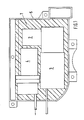
- Fig. 1 eine Draufsicht auf eine in einem schalenförmigen Behältnis angeordnete Kompressoreinheit, bestehend aus Druckkompressor, Motor und Lufttrockner,
- Fig. 2 eine Draufsicht gemäß Fig. 1 mit einer über ein Schalldämmelement und einem Wärmespeicher abgedeckten Kompressoreinheit,
- Fig. 3 einen Schnitt nach der Linie III-III der Fig. 2, und
- Fig. 4 einen Schnitt nach der Linie IV-IV der Fig. 3.
- Die Vorrichtung ist in einem Kraftfahrzeug eingebaut und umfaßt im wesentlichen eine Kompressoreinheit 1, bestehend aus einem Druckluftkompressor 2 für eine Energieversorgung einer pneumatischen Niveauregelanlage, die nicht näher gezeigt ist. Mit dem Kompressor 2 ist ein Elektromotor 3 und ein Lufttrockner 4 verbunden.
- Diese Einheit 1 ist in einem schalenförmigen Behältnis 5 angeordnet und über ein schallminderndes unteres Element 6 zum Boden 7 des Behältnisses 5 hin elastisch abgestützt. Das Element 6 ist als Halbschale ausgeführt und umgibt die Einheit bis zu einer Ebene X-X allseitig. Diese Ebene X-X verläuft etwa in einer Mittelquerebene der Aggregate 3 und 4. Ein weiteres schallminderndes oberes und als Halbschale ausgeführtes Element 8 schließt sich lückenlos an das untere Halbschalen-Element 6 an und umgibt alle Aggregate 2, 3 und 4.
- Die Kompressoreinheit 1 ist mit ihrer im Behältnis 5 freiliegenden Seite von einem Wärmespeicher 9 abgedeckt, der in einem Ausschnitt 10 des oberen Elements 8 eingebettet gehalten ist.
- Die Halbschalen der schallmindernden Elemente 6 und 8 sowie der Wärmespeicher sind den Konturen der Gehäuse der Pumpe 2, des Motors 3 und des Lufttrockners 4 weitestgehend angepasst, so daß insbesondere der Wärmespeicher 9 einen unmittelbaren flächigen Kontakt mit diesen Aggregaten aufweist und ein optimaler Wärmeübergang gewährleistet ist.
- Das schalenförmige Behältnis 5 wird mit einer Aufbauwand 10 des Fahrzeugs verbunden, an die eine Wand 11 des Wärmespeichers 9 anliegend ist, wodurch zusätzlich Wärme abgeführt wird. Diese Wand 11 ist gegenüberstehend einer weiteren Wand 12 vorgesehen, welche mit den Gehäusen der Aggregate 2, 3 und 4 in Kontakt steht. Wie Fig. 4 näher zeigt, ist auch die Halbschale 8 dem Verlauf der Aufbauwand 10 angepasst.
- Der Wärmespeicher 9 besteht vorzugsweise aus einem dünnwandigen Kunststoffbehälter, dessen Wände flexibel ausgeführt sind. Die den Aggregaten zugerichtete Wand 12 ist dicker ausgeführt als die gegenüberliegende Wand 11, um durch Reibung der Aggregate verursachten Abnutzungen entgegenzuwirken. Der Wärmespeicher 9 ist mit einer Flüssigkeit, bestehend aus einem Gemisch aus Wasser und Frostschutzmittel gefüllt.
- Die Halbschalen 6 und 8 umschließen die Einheit 1 rundum stirnseitig sowie oben- und unterseitig im Behältnis 5, wobei der Wärmespeicher 9 neben seiner Funktion als Wärmeabfuhrelement zusätzlich auch schallmindernd wirkt und hierzu paßgenau in eine Öffnung 13 der oberen Halbschale 8 eingefügt ist, wie Fig. 2 näher zeigt. Desweiteren zeigt Fig. 2 auch, daß der Wärmespeicher 9 hauptsächlich den die meiste Wärme verursachenden E-Motor 3 und den Lufttrockner 4 überdeckt, welche wesentliche Wärmequellen darstellt, so daß ein Wärmeübergang zum Druckluftkompressor 2 unterbunden wird. Eine weitere Erstreckung z.B. über die gesamte Einheit 1 ist ebenfalls möglich, zumal eine Schallminderung auch durch den Wärmespeicher erzielt wird.
Claims (6)
Applications Claiming Priority (2)
| Application Number | Priority Date | Filing Date | Title |
|---|---|---|---|
| DE3909563A DE3909563A1 (de) | 1989-03-23 | 1989-03-23 | Vorrichtung zur kuehlung und geraeuschdaempfung einer druckluftkompressoreinheit |
| DE3909563 | 1989-03-23 |
Publications (2)
| Publication Number | Publication Date |
|---|---|
| EP0388525A1 true EP0388525A1 (de) | 1990-09-26 |
| EP0388525B1 EP0388525B1 (de) | 1993-03-03 |
Family
ID=6377039
Family Applications (1)
| Application Number | Title | Priority Date | Filing Date |
|---|---|---|---|
| EP89123104A Expired - Lifetime EP0388525B1 (de) | 1989-03-23 | 1989-12-14 | Vorrichtung zur Kühlung und Geräuschdämpfung einer Druckluftkompressoreinheit |
Country Status (2)
| Country | Link |
|---|---|
| EP (1) | EP0388525B1 (de) |
| DE (2) | DE3909563A1 (de) |
Cited By (7)
| Publication number | Priority date | Publication date | Assignee | Title |
|---|---|---|---|---|
| WO1999022794A1 (en) * | 1997-11-03 | 1999-05-14 | Resmed Limited | Noise damping mounting body for cpap compressor |
| US6776155B2 (en) | 1997-05-16 | 2004-08-17 | Resmed Limited | Nasal ventilation as a treatment for stroke |
| US6810876B2 (en) | 1996-09-23 | 2004-11-02 | Resmed Ltd. | Assisted ventilation to match patient respiratory need |
| EP1596067A1 (de) * | 2004-05-14 | 2005-11-16 | COPELAND CORPORATION (a Delaware corp.) | Schalldämpfung für Verdichter |
| US7302950B2 (en) | 1991-12-20 | 2007-12-04 | Resmed Limited | Patient interface for respiratory apparatus |
| EP2423015A1 (de) * | 2010-08-27 | 2012-02-29 | Spheros GmbH | Vorrichtung zur schwingungsdämpfenden Lagerung eines Aggregates |
| US9153225B2 (en) | 2011-12-16 | 2015-10-06 | Emerson Climate Technologies, Inc. | Sound enclosure for enclosing a compressor assembly |
Families Citing this family (8)
| Publication number | Priority date | Publication date | Assignee | Title |
|---|---|---|---|---|
| DE19522895C2 (de) * | 1995-06-23 | 1998-10-15 | Daimler Benz Ag | Aus zwei Halbschalen bestehende, ein Geräusche abgebendes Bauteil in einem Kraftwagen umgebende Kunststoffverkleidung |
| EP0862474A4 (de) | 1995-09-18 | 2000-05-03 | Resmed Ltd | Druckregelung bei cpap-behandlung oder bei assistierte beatmung |
| AUPO742297A0 (en) | 1997-06-18 | 1997-07-10 | Resmed Limited | An apparatus for supplying breathable gas |
| DE19820818C2 (de) * | 1998-05-09 | 2002-12-05 | Viessmann Werke Kg | Wärmepumpe |
| DE102008027207A1 (de) * | 2008-06-06 | 2009-12-10 | Bayerische Motoren Werke Aktiengesellschaft | Kraftfahrzeug mit einem Motorraum |
| DE102011003133A1 (de) * | 2011-01-25 | 2012-07-26 | Bayerische Motoren Werke Aktiengesellschaft | Maschinenhalterung in einem Fahrzeug |
| DE102019131835A1 (de) * | 2019-11-25 | 2021-05-27 | Bayerische Motoren Werke Aktiengesellschaft | Verdichtereinrichtung für ein Fahrzeug, insbesondere für ein Kraftfahrzeug, sowie Fahrzeug |
| JP7347305B2 (ja) | 2020-03-31 | 2023-09-20 | 株式会社豊田自動織機 | 電動圧縮機 |
Citations (3)
| Publication number | Priority date | Publication date | Assignee | Title |
|---|---|---|---|---|
| DE1809941U (de) * | 1960-02-10 | 1960-04-21 | Kloeckner Humboldt Deutz Ag | Achsangetriebener kompressor. |
| US3830596A (en) * | 1972-01-18 | 1974-08-20 | R Kondo | Air pump |
| DE2804653A1 (de) * | 1978-01-24 | 1979-08-09 | Bjoern Olov Erling Olofsson | Vorrichtung zur kuehlung und geraeuschdaempfung von kompressoren und vakuumpumpen |
Family Cites Families (4)
| Publication number | Priority date | Publication date | Assignee | Title |
|---|---|---|---|---|
| DE688946C (de) * | 1938-03-24 | 1940-03-06 | Siemens Schuckertwerke Akt Ges | Foerderpumpe, insbesondere Kompressor fuer Kaeltemaschinen |
| DE1051295B (de) * | 1957-02-16 | 1959-02-26 | Wilhelm Bock | Verfluessiger-Aggregat fuer Kaeltemaschinen |
| DE2804563A1 (de) * | 1978-02-03 | 1979-08-09 | Guenter Dipl Chem Dr Koenig | Mittel gegen knospenfrass an nutz- und bluetenstraeuchern |
| DE3323561A1 (de) * | 1983-06-30 | 1984-03-15 | Daimler-Benz Ag, 7000 Stuttgart | Schaumstoff-ummantelung zur geraeuschdaemmung fuer eine luftpumpe |
-
1989
- 1989-03-23 DE DE3909563A patent/DE3909563A1/de active Granted
- 1989-12-14 EP EP89123104A patent/EP0388525B1/de not_active Expired - Lifetime
- 1989-12-14 DE DE8989123104T patent/DE58903680D1/de not_active Expired - Fee Related
Patent Citations (3)
| Publication number | Priority date | Publication date | Assignee | Title |
|---|---|---|---|---|
| DE1809941U (de) * | 1960-02-10 | 1960-04-21 | Kloeckner Humboldt Deutz Ag | Achsangetriebener kompressor. |
| US3830596A (en) * | 1972-01-18 | 1974-08-20 | R Kondo | Air pump |
| DE2804653A1 (de) * | 1978-01-24 | 1979-08-09 | Bjoern Olov Erling Olofsson | Vorrichtung zur kuehlung und geraeuschdaempfung von kompressoren und vakuumpumpen |
Cited By (14)
| Publication number | Priority date | Publication date | Assignee | Title |
|---|---|---|---|---|
| US7302950B2 (en) | 1991-12-20 | 2007-12-04 | Resmed Limited | Patient interface for respiratory apparatus |
| US7931023B2 (en) | 1991-12-20 | 2011-04-26 | Resmed Limited | Patient interface assembly for CPAP respiratory apparatus |
| US8733351B2 (en) | 1996-09-23 | 2014-05-27 | Resmed Limited | Method and apparatus for providing ventilatory assistance |
| US6810876B2 (en) | 1996-09-23 | 2004-11-02 | Resmed Ltd. | Assisted ventilation to match patient respiratory need |
| US7137389B2 (en) | 1996-09-23 | 2006-11-21 | Resmed Limited | Method and apparatus for determining instantaneous inspired volume of a subject during ventilatory assistance |
| US9974911B2 (en) | 1996-09-23 | 2018-05-22 | Resmed Limited | Method and apparatus for providing ventilatory assistance |
| US7644713B2 (en) | 1996-09-23 | 2010-01-12 | Resmed Limited | Method and apparatus for determining instantaneous leak during ventilatory assistance |
| US8051853B2 (en) | 1996-09-23 | 2011-11-08 | Resmed Limited | Method and apparatus for providing ventilatory assistance |
| US6776155B2 (en) | 1997-05-16 | 2004-08-17 | Resmed Limited | Nasal ventilation as a treatment for stroke |
| WO1999022794A1 (en) * | 1997-11-03 | 1999-05-14 | Resmed Limited | Noise damping mounting body for cpap compressor |
| EP1596067A1 (de) * | 2004-05-14 | 2005-11-16 | COPELAND CORPORATION (a Delaware corp.) | Schalldämpfung für Verdichter |
| US7398855B2 (en) | 2004-05-14 | 2008-07-15 | Emerson Climate Technologies, Inc. | Compressor sound attenuation enclosure |
| EP2423015A1 (de) * | 2010-08-27 | 2012-02-29 | Spheros GmbH | Vorrichtung zur schwingungsdämpfenden Lagerung eines Aggregates |
| US9153225B2 (en) | 2011-12-16 | 2015-10-06 | Emerson Climate Technologies, Inc. | Sound enclosure for enclosing a compressor assembly |
Also Published As
| Publication number | Publication date |
|---|---|
| DE3909563C2 (de) | 1992-09-17 |
| DE58903680D1 (de) | 1993-04-08 |
| DE3909563A1 (de) | 1990-09-27 |
| EP0388525B1 (de) | 1993-03-03 |
Similar Documents
| Publication | Publication Date | Title |
|---|---|---|
| EP0388525B1 (de) | Vorrichtung zur Kühlung und Geräuschdämpfung einer Druckluftkompressoreinheit | |
| EP0958646B2 (de) | Elektromotor mit vorgeschaltetem frequenzumrichter | |
| DE69702033T2 (de) | Elektronisches Steuergerät mit Kühlkörper | |
| DE19959632B4 (de) | Hydraulische Steuervorrichtung mit integrierter Motorantriebsschaltung | |
| DE4015080C2 (de) | Klemmenkasten für einen frequenzumrichtergespeisten Elektromotor | |
| DE112007000991T5 (de) | Kondensatormodul | |
| DE10329843A1 (de) | Verfahren zum wasserdichten Abdichten eines Leistungsschaltkreisabschnittes und Leistungsmodul mit einem derartigen Leistungsschaltkreisabschnitt | |
| DE29909117U1 (de) | Hermetisches Kompressoraggregat mit verbesserten Steuer- und Kontrolleinrichtungen | |
| EP3124881A1 (de) | Peltierluftentfeuchter für den einbau in einen behälter | |
| DE102007024320A1 (de) | Batteriemodul für ein elektrisches Handwerkzeug | |
| EP0705530B1 (de) | Stromrichtermodul | |
| DE10306692A1 (de) | Stromversorgungseinheit | |
| EP0294500B1 (de) | Wärmespeicher, insbesondere für durch Motorabwärme gespeiste Kraftfahrzeugheizungen | |
| DE19512804C2 (de) | Hydraulikaggregat für eine blockiergeschützte Fahrzeugbremsanlage | |
| WO2023147816A1 (de) | Elektrisches system und elektrische antriebseinheit | |
| EP1343671A1 (de) | Aggregat mit einem motor | |
| EP3928600B1 (de) | Gehäuseanordnung | |
| EP1289011A2 (de) | Schalt- oder Steuergerät | |
| DE19813365A1 (de) | Stromrichterbaugruppe für ein Stromrichtergerät | |
| DE10050367A1 (de) | Halterungsaufbau für eine elektrische Einrichtung in einem tragbaren elektrischen Werkzeug | |
| EP1104079B1 (de) | Elektromotor für insbesondere eine Kreiselpumpe | |
| DE19904279B4 (de) | Halbleitervorrichtung | |
| EP1968170B1 (de) | Antriebseinheit insbesondere für Flurförderzeug | |
| DE3305301A1 (de) | Antriebsvorrichtung | |
| DE10032306B4 (de) | Mit Motor vereinigte Steuerung und in dieser verwendete Schaltungsplatinengehäuse |
Legal Events
| Date | Code | Title | Description |
|---|---|---|---|
| PUAI | Public reference made under article 153(3) epc to a published international application that has entered the european phase |
Free format text: ORIGINAL CODE: 0009012 |
|
| AK | Designated contracting states |
Kind code of ref document: A1 Designated state(s): DE FR GB IT |
|
| 17P | Request for examination filed |
Effective date: 19901221 |
|
| 17Q | First examination report despatched |
Effective date: 19920529 |
|
| ITF | It: translation for a ep patent filed | ||
| GRAA | (expected) grant |
Free format text: ORIGINAL CODE: 0009210 |
|
| AK | Designated contracting states |
Kind code of ref document: B1 Designated state(s): DE FR GB IT |
|
| REF | Corresponds to: |
Ref document number: 58903680 Country of ref document: DE Date of ref document: 19930408 |
|
| GBT | Gb: translation of ep patent filed (gb section 77(6)(a)/1977) |
Effective date: 19930317 |
|
| ET | Fr: translation filed | ||
| PG25 | Lapsed in a contracting state [announced via postgrant information from national office to epo] |
Ref country code: GB Effective date: 19931214 |
|
| PLBE | No opposition filed within time limit |
Free format text: ORIGINAL CODE: 0009261 |
|
| STAA | Information on the status of an ep patent application or granted ep patent |
Free format text: STATUS: NO OPPOSITION FILED WITHIN TIME LIMIT |
|
| 26N | No opposition filed | ||
| GBPC | Gb: european patent ceased through non-payment of renewal fee |
Effective date: 19931214 |
|
| PG25 | Lapsed in a contracting state [announced via postgrant information from national office to epo] |
Ref country code: FR Effective date: 19940831 |
|
| PG25 | Lapsed in a contracting state [announced via postgrant information from national office to epo] |
Ref country code: DE Effective date: 19940901 |
|
| REG | Reference to a national code |
Ref country code: FR Ref legal event code: ST |
|
| PG25 | Lapsed in a contracting state [announced via postgrant information from national office to epo] |
Ref country code: IT Free format text: LAPSE BECAUSE OF NON-PAYMENT OF DUE FEES;WARNING: LAPSES OF ITALIAN PATENTS WITH EFFECTIVE DATE BEFORE 2007 MAY HAVE OCCURRED AT ANY TIME BEFORE 2007. THE CORRECT EFFECTIVE DATE MAY BE DIFFERENT FROM THE ONE RECORDED. Effective date: 20051214 |