EP0387773B1 - Automatically fittable and illuminated electrical cigar lighter - Google Patents
Automatically fittable and illuminated electrical cigar lighter Download PDFInfo
- Publication number
- EP0387773B1 EP0387773B1 EP90104697A EP90104697A EP0387773B1 EP 0387773 B1 EP0387773 B1 EP 0387773B1 EP 90104697 A EP90104697 A EP 90104697A EP 90104697 A EP90104697 A EP 90104697A EP 0387773 B1 EP0387773 B1 EP 0387773B1
- Authority
- EP
- European Patent Office
- Prior art keywords
- cigar lighter
- lighter according
- electric cigar
- cup
- dashboard
- Prior art date
- Legal status (The legal status is an assumption and is not a legal conclusion. Google has not performed a legal analysis and makes no representation as to the accuracy of the status listed.)
- Expired - Lifetime
Links
Images


Classifications
-
- B—PERFORMING OPERATIONS; TRANSPORTING
- B60—VEHICLES IN GENERAL
- B60N—SEATS SPECIALLY ADAPTED FOR VEHICLES; VEHICLE PASSENGER ACCOMMODATION NOT OTHERWISE PROVIDED FOR
- B60N3/00—Arrangements or adaptations of other passenger fittings, not otherwise provided for
- B60N3/14—Arrangements or adaptations of other passenger fittings, not otherwise provided for of electrically-heated lighters
Definitions
- the invention relates to an electric cigar lighter according to the preamble of claim 1.
- an electric cigar lighter to be installed in particular in the dashboard of a motor vehicle is known, the lighting device of which essentially consists of a lamp, a lamp housing and a light ring arranged between the dashboard and the cigar lighter socket.
- This lighting device known in the prior art is in need of improvement from the point of view of an assembly-oriented product design, the latter being a prerequisite for economical assembly automation. So it is disadvantageous, for example, lamp and Arrange the lamp housing eccentrically outside the area specified by the light ring diameter. For this reason, the known lighting device does not allow a linear joining movement when inserted into the installation opening of the dashboard. Instead, a curved installation movement is required, which prevents the use of assembly robots. It is also disadvantageous that the lighting device cannot be preassembled together with the socket in the supplying plant, as a result of which three individual assembly steps are required in the automobile plant.
- the socket So after inserting the light ring, the socket must be sunk into its opening, the light ring being held until the clamping tongues formed in the light ring are spread out by the inserted socket for the purpose of locking in the dashboard. These clamping tongues also deteriorate the uniform light distribution in the light ring. The correct mutual positioning of the light ring and socket must also be ensured. For this purpose, directional tongues in the illuminated ring are required, which break away when the socket is inserted. Finally, in a third assembly step, a mating connector located in the rear part of the dashboard for the power supply to the lamp and the cigar lighter heating element must be connected. Furthermore, the lighting device known in the prior art also has a relatively large number of individual parts. The lamp holder alone consists of five individual parts, plus the lamp housing with the sliding contact tab required for the ground contact to be made to the socket and the light ring itself.
- the socket can now be preassembled in the adapter sleeve on the supplier side.
- the jointly preassembled clamping sleeve and socket can be inserted into the dashboard opening of a motor vehicle by an industrial robot with the aid of a linear joining movement. Due to the central penetration of all contact parts arranged on the cup base of the socket through the cup base of the adapter sleeve, a central connection is ensured, which offers further assembly advantages. With a single straight insertion movement, the vehicle electrical system connector can already be contacted.
- the adapter sleeve according to the invention can be preassembled with the socket, it is necessary to design the latching of the adapter sleeve in the dashboard independently of the separate insertion of the socket disclosed in the prior art.
- several groups of clamping ribs of different lengths are therefore arranged rotationally symmetrically on the surface of the preferably hollow cylindrical cup wall of the clamping sleeve. In this way, with the holding forces remaining constant on the periphery, a secure locking of the clamping sleeve can be achieved with a single joining movement even with dashboards of different thicknesses.
- the cup base is beveled conically in the form of a truncated cone.
- the contact parts can also be designed as contact tabs, which, in conjunction with a T-shaped or I-shaped arrangement of the contact parts, already provides a coding of the contact parts desired for the azimuthal alignment of the clamping sleeve.
- the contact parts reaching through the cup base in the form of a coaxial connection.
- strip-shaped light passage slots can be provided in the hollow cylindrical, coaxially arranged ring contacts, so that the light of a lamp, preferably arranged centrally axially in the cup base, can flood into the material of the cup wall.
- the coaxial connection can also be arranged on the outside of the connector plug on the bottom of the clamping sleeve, as a result of which no light passage slots are then required.
- a rotationally symmetrical arrangement of the contact parts and the lamp is additionally created, which enables completely direction-independent automatic assembly.
- the lamp receptacle can be formed eccentrically or centrally axially in the cup base and can be open-shaped on the connector side. This enables the lamp itself to be installed in the connector, while the location of the greatest luminance is within the cup base.
- the lamp receptacle in the wall of the cup base is aligned radially and in this case pierces a centrally arranged contact part designed as a contact lug in a bore provided in it.
- This combines the advantages of a central arrangement of the contact parts with the advantage of a central arrangement of the lamp.
- the sliding contact lug on the lamp housing which is still required in the prior art and which establishes the ground connection, is dispensed with, since in this arrangement the lamp connecting wires can be soldered directly to the corresponding contact parts.
- the shape of the clamping ribs which serves to lock the clamping sleeve in place is preferably aligned equidistantly and parallel to the axis. This ensures a rotationally symmetrical distribution of the latching forces.
- the individual clamping ribs have run-on bevels, which enables easy insertion of the clamping sleeve into a preferably thermoplastic dashboard.
- the cross-sectional profiles of the clamping ribs are advantageously designed to be elastic, so that the clamping ribs first deflect during the sliding on and spring open again behind the pushed-on dashboard.
- cavities 16 can preferably be present under the clamping ribs 20 in order to enable the clamping ribs 20 to have a spring effect. In this way, an almost vibration and twist-proof assembly of the adapter sleeve according to the invention is guaranteed in the dashboard.
- the clamping sleeve 1 shows a median section of a first exemplary embodiment of the clamping sleeve 1 according to the invention, together with the socket 2 which it largely embraces in a form-fitting manner.
- the clamping sleeve 1 has a cup wall 3 with a cup base 4 formed integrally from light-conducting material.
- the cup wall 3 is in the form of a straight hollow cylinder formed, whereas the cup bottom 4 is substantially fully cylindrical, the cup bottom 4 being beveled in the shape of a truncated cone by means of a bevel 22 and the cup wall 3 and cup bottom 4 having a circular cross-sectional area.
- other, for example elliptical, cross-sectional areas are also conceivable.
- a first plus potential contact part 5 and a minus potential contact part 7 are arranged on the bottom of the socket 2, which is also cup-shaped and accommodates a holding body together with the glow head (not shown). Therefor the cup bottom 4 has a cone-shaped receptacle 32.
- a second plus potential contact part 6 (FIG. 4.5) is locked in the cup base 4 of the clamping sleeve 1 without reaching through the cup base 4.
- the contact parts 5, 7 extend through recesses 12 formed in the cup base 4 (FIG. 2). All contact parts 5, 6, 7 are arranged within a spatial area delimited by a fictitious hollow cylinder surface MF 'of a fictitious hollow cylinder.
- the fictitious hollow cylinder surface MF 'adjoins the cup wall 3 in the socket insertion direction, the outer diameter of the fictitious hollow cylinder corresponding to the outer diameter of the clamping sleeve 1.
- the assembly movement of an assembly robot runs along a central axis ZA.
- the clamping sleeve 1 is securely locked behind a dashboard 18 with the aid of clamping ribs 20 which have run-on bevels 21.
- the enlarged detail view b) shows a variant of the clamping ribs 20 with an additional run-off slope 28.
- a corresponding bevel on the dashboard 18 additionally supports the snap-on operation of the clamping sleeve 1.
- FIGS. 2, 3 show further sides (sectional) views of the adapter sleeve 1 according to the first embodiment.
- the lighting clamping cup sleeve 1 has locking lugs 27 integrally molded thereon for locking them in the socket 2.
- a lamp holder 10 is formed radially in the cup base 4 and is open laterally.
- a lamp 9, preferably a long-life lamp with a 104 hour burn time, can be inserted here and with Lamp connecting wires 11 to the second positive potential contact part 6 and to the negative potential contact part 7 are conductively connected.
- the cup base 4 has a truncated cone-shaped bevel 22, which facilitates the insertion of the clamping sleeve into the dashboard 18.
- Fig. 4 shows a plan view of the arrangement of the contact parts 5,6,7 of the first embodiment.
- the contact parts 6, 7 are connected to the lamp 9 via lamp connecting wires 11.
- the minus potential contact part 7 contacts the cup wall of the metal socket 2, whereas the first plus potential contact part 5 applies potential to the bimetallic springs 15 which are insulated from the socket 2.
- the clamping ribs 20 are arranged in groups 24 of clamping ribs 20 arranged in a rotationally symmetrical manner. Each group 24 has clamping ribs 20 of different lengths, the distance between the end of a clamping rib 20 and an illuminated ring 19 formed on the cup wall 3 corresponding to the wall thickness of the dashboards 18.
- the clamping ribs 20 can have a right-angled or a beveled end, as the detailed views of FIG. 1 show.
- one or more steel springs 17 can also spring out behind the dashboard 18 and lock the cup wall 3, as shown in particular in FIG. 2.
- all relevant known fasteners thread, adhesive, etc.
- FIG. 6 shows a cross section through the clamping sleeve 1 along the section line VI-VI in FIG. 5. Between the socket 2 and the cup wall 3, spacing webs 29 and cavities 16 are provided in order to enable the clamping ribs 20 to have a spring effect.
- FIG. 7 shows the side sectional view of the clamping sleeve 1 according to the invention in accordance with a second exemplary embodiment, in which the contact parts 5, 7 contacting the connector 8 are designed as a coaxial connection. If necessary, additional contact parts can be arranged coaxially.
- the lamp holder 10 for the lamp 9 is provided axially centered.
- the lamp 9 is installed in the connector 8, while the place of greatest luminance is in the center of the cup base 4.
- an extension 30 is formed on the cup base 4, which forms a dovetail locking mechanism with the material of the connector 8.
- the contact parts 5, 7 formed as hollow cylindrical ring contacts must have strip-shaped light passage slots 23, as shown in FIG. 8.
- FIG. 8 shows a top view of the coaxial arrangement of the contact parts 5, 7 provided with the light passage slots 23 according to the second exemplary embodiment in FIG. 7.
- Fig. 9 shows a side sectional view of the clamping sleeve 1 according to the invention according to a third embodiment.
- the lamp 9 is arranged eccentrically axially in the cup base 4.
Landscapes
- Engineering & Computer Science (AREA)
- Transportation (AREA)
- Mechanical Engineering (AREA)
- Arrangements Of Lighting Devices For Vehicle Interiors, Mounting And Supporting Thereof, Circuits Therefore (AREA)
- Instrument Panels (AREA)
- Fastening Of Light Sources Or Lamp Holders (AREA)
- Coupling Device And Connection With Printed Circuit (AREA)
Description
Die Erfindung betrifft einen elektrischen Zigarrenanzünder nach dem Oberbegriff des Anspruchs 1.The invention relates to an electric cigar lighter according to the preamble of
Wirtschaftliche Montageautomatisierung stellt ein wesentliches Rationalisierungspotential der Zukunft dar, insbesondere unter dem zunehmendem Wettbewerbsdruck, alle Rationalisierungsreserven der Fertigungstechnik auszuschöpfen.Economic assembly automation represents a significant rationalization potential of the future, especially under increasing competitive pressure to exhaust all rationalization reserves of manufacturing technology.
Aus der DE-PS 25 35 080 ist ein insbesondere in das Armaturenbrett eines Kraftfahrzeugs zu installierender elektrischer Zigarrenanzünder bekannt, dessen Beleuchtungseinrichtung im wesentlichen aus einer Lampe, einem Lampengehäuse und einem zwischen dem Armaturenbrett und der Zigarrenanzünder-Steckdose angeordneten Leuchtring besteht.From DE-PS 25 35 080 an electric cigar lighter to be installed in particular in the dashboard of a motor vehicle is known, the lighting device of which essentially consists of a lamp, a lamp housing and a light ring arranged between the dashboard and the cigar lighter socket.
Diese im Stand der Technik bekannte Beleuchtungseinrichtung ist unter dem Gesichtspunkt einer montagegerechten Produktgestaltung noch verbesserungswürdig, wobei letztere Voraussetzung einer wirtschaftlichen Montageautomatisierung ist. So ist es bspw. nachteilig, Lampe und Lampengehäuse exzentrisch außerhalb des durch den Leuchtringdurchmesser vorgegebenen Raumbereichs anzuordnen. Aus diesem Grunde gestattet die bekannte Beleuchtungseinrichtung beim Einsetzen in die Installationsöffnung des Armaturenbretts keine lineare Fügebewegung. Statt dessen ist eine gekrümmte Einbaubewegung erforderlich, was dem Einsatz von Montagerobotern entgegensteht. Auch ist nachteilig, daß die Beleuchtungseinrichtung nicht gemeinsam mit der Steckdose im Zulieferwerk vormontiert werden kann, wodurch im Automobilwerk drei einzelne Montageschritte erforderlich werden. So muß nach dem Einsetzen des Leuchtrings die Steckdose in dessen Öffnung versenkt werden, wobei der Leuchtring solange festzuhalten ist, bis die im Leuchtring ausgebildeten Klemmzungen von der eingeschobenen Steckdose zum Zwecke der Verrastung im Armaturenbrett aufgespreizt sind. Diese Klemmzungen verschlechtern ferner auch die gleichmäßige Lichtverteilung im Leuchtring. Hierbei ist zusätzlich auf die richtige gegenseitige Positionierung von Leuchtring und Steckdose zu achten. Zu diesem Zweck sind Richtzungen im Leuchtring erforderlich, die beim Einsetzen der Steckdose wegbrechen. In einem dritten Montageschritt muß schließlich noch ein im rückwärtigen Teil des Armaturenbretts befindlicher Gegenstecker für die Stromversorgung der Lampe und des Zigarrenanzünder-Heizelements angeschlossen werden. Ferner weist die im Stand der Technik bekannte Beleuchtungseinrichtung auch noch relativ viele Einzelteile auf. So besteht allein die Lampenfassung aus fünf Einzelteilen, wozu noch das Lampengehäuse mit der wegen des zur Steckdose herzustellenden Massekontaktes erforderlichen Schleifkontaktfahne und der Leuchtring selbst hinzukommen.This lighting device known in the prior art is in need of improvement from the point of view of an assembly-oriented product design, the latter being a prerequisite for economical assembly automation. So it is disadvantageous, for example, lamp and Arrange the lamp housing eccentrically outside the area specified by the light ring diameter. For this reason, the known lighting device does not allow a linear joining movement when inserted into the installation opening of the dashboard. Instead, a curved installation movement is required, which prevents the use of assembly robots. It is also disadvantageous that the lighting device cannot be preassembled together with the socket in the supplying plant, as a result of which three individual assembly steps are required in the automobile plant. So after inserting the light ring, the socket must be sunk into its opening, the light ring being held until the clamping tongues formed in the light ring are spread out by the inserted socket for the purpose of locking in the dashboard. These clamping tongues also deteriorate the uniform light distribution in the light ring. The correct mutual positioning of the light ring and socket must also be ensured. For this purpose, directional tongues in the illuminated ring are required, which break away when the socket is inserted. Finally, in a third assembly step, a mating connector located in the rear part of the dashboard for the power supply to the lamp and the cigar lighter heating element must be connected. Furthermore, the lighting device known in the prior art also has a relatively large number of individual parts. The lamp holder alone consists of five individual parts, plus the lamp housing with the sliding contact tab required for the ground contact to be made to the socket and the light ring itself.
Es ist deshalb Aufgabe der Erfindung, unter Vermeidung vorgenannter Nachteile die Beleuchtungs- und Spannvorrichtung eines elektrischen Zigarrenanzünders der im Oberbegriff des Anspruchs 1 genannten Art derart montagegerecht auszubilden, daß eine zeit- und kostengünstige Montageautomatisierung unter Zuhilfenahme von Industrierobotern erreichbar ist.It is therefore an object of the invention, while avoiding the above-mentioned disadvantages, to design the lighting and tensioning device of an electric cigar lighter of the type mentioned in the preamble of
Diese Aufgabe wird durch die im Anspruch 1 näher gekennzeichneten Merkmale gelöst.This object is achieved by the features characterized in more detail in
Weitere Ausgestaltungen der Erfindung sind in den Unteransprüchen näher gekennzeichnet.Further embodiments of the invention are characterized in more detail in the subclaims.
Dadurch, daß die die Lampe tragende Spannhülse becherförmig ausgebildet ist und damit die Steckdose weitgehend formschlüssig aufnimmt, ist eine endmontagefreundliche Produktgestaltung erreicht. Wegen der gegenüber dem Stand der Technik nicht mehr vorhandenen exzentrischen Lampenanordnung läßt sich nunmehr die Steckdose zulieferwerkseitig in der Spannhülse vormontieren. Die gemeinsam vormontierte Spannhülse nebst Steckdose läßt sich von einem Industrieroboter mit Hilfe einer linearen Fügebewegung in die Armaturenbrettöffnung eines Kraftfahrzeugs einführen. Aufgrund des zentralen Durchgriffs aller am Becherboden der Steckdose angeordneten Kontaktteile durch den Becherboden der Spannhülse ist ein Zentralanschluß gewährleistet, welcher weitere Montagevorteile bietet. So läßt sich mit Hilfe einer einzigen geradlinigen Einführfügebewegung auch bereits der Bordnetz-Anschlußstecker kontaktieren. Ein nachträgliches Aufstecken des Anschlußsteckers entfällt somit. Dadurch, daß die Lampenaufnahme für die Lampe im zwischen Becherwandung und Anschlußstecker vorgesehenen Becherboden augebildet ist, wird die im Stand der Technik als nachteilig erkannte Exzentrizität der Lampenanordnung vermieden. Weil das Licht nunmehr im wesentlichen zentral achsennah im Raumbereich des Becherbodens der Spannhülse erzeugt wird und ins kompakte Material des Becherbodens einflutet, wird nach Fortleitung des Lichtes über die Mantelfläche der Becherwandung eine äußerst homogene Lichtverteilung im frontseitig angeordneten Leuchtring erzeugt, wohingegen bei der im Stand der Technik bekannten Anordnung der Lampe das Licht lateral in das Material einflutet, wodurch sich unerwünschte Helligkeitsgradienten entlang des Leuchtrings einstellen.Characterized in that the clamping sleeve carrying the lamp is cup-shaped and thus largely receives the socket in a form-fitting manner, an assembly-friendly product design is achieved. Because of the eccentric lamp arrangement that is no longer available compared to the prior art, the socket can now be preassembled in the adapter sleeve on the supplier side. The jointly preassembled clamping sleeve and socket can be inserted into the dashboard opening of a motor vehicle by an industrial robot with the aid of a linear joining movement. Due to the central penetration of all contact parts arranged on the cup base of the socket through the cup base of the adapter sleeve, a central connection is ensured, which offers further assembly advantages. With a single straight insertion movement, the vehicle electrical system connector can already be contacted. A subsequent plugging in of the connector is therefore not necessary. The fact that the lamp holder for the lamp in the cup bottom provided between the cup wall and the connector is formed, the eccentricity of the lamp arrangement recognized as disadvantageous in the prior art is avoided. Because the light is now generated essentially centrally close to the axis in the area of the cup base of the adapter sleeve and floods into the compact material of the cup base, an extremely homogeneous light distribution in the light ring arranged on the front side is generated after the light is transmitted over the lateral surface of the cup wall, whereas in the state of the Technically known arrangement of the lamp laterally floods the light into the material, which results in undesired brightness gradients along the light ring.
Da die erfindungsgemäße Spannhülse mit der Steckdose vormontiert werden kann, ist es erforderlich, die Verrastung der Spannhülse im Armaturenbrett unabhängig von dem im Stand der Technik offenbarten getrennten Einfügen der Steckdose auszubilden. Nach einer bevorzugten Ausführungsform sind deshalb auf der Oberfläche der vorzugsweise hohlzylinderförmigen Becherwandung der Spannhülse mehrere Gruppen unterschiedlich langer Klemmrippen rotationssymmetrisch angeordnet. Hierdurch läßt sich bei peripher gleichbleibenden Haltekräften in einfacher Weise eine sichere Verrastung der Spannhülse auch bei unterschiedlich dicken Armaturenbrettern mit einer einzigen Fügebewegung erreichen.Since the adapter sleeve according to the invention can be preassembled with the socket, it is necessary to design the latching of the adapter sleeve in the dashboard independently of the separate insertion of the socket disclosed in the prior art. According to a preferred embodiment, several groups of clamping ribs of different lengths are therefore arranged rotationally symmetrically on the surface of the preferably hollow cylindrical cup wall of the clamping sleeve. In this way, with the holding forces remaining constant on the periphery, a secure locking of the clamping sleeve can be achieved with a single joining movement even with dashboards of different thicknesses.
In vorteilhafter Weiterbildung der Erfindung ist außerdem vorgesehen, daß der Becherboden konusförmig in Form eines Kegelstumpfes angeschrägt ist. Hierdurch toleriert der Montageroboter kleine Ausrichtungsabweichungen bei der Teileaufnahme, so daß stets eine nichtklemmende Einfügung der Spannhülse gewährleistet ist.In an advantageous development of the invention it is also provided that the cup base is beveled conically in the form of a truncated cone. As a result, the assembly robot tolerates small alignment deviations when picking up parts, so that a non-clamping insertion of the clamping sleeve is always guaranteed.
Herkömmlicherweise können die Kontaktteile auch als Kontaktfahnen ausgestaltet sein, wodurch in Verbindung mit einer T-förmigen oder I-förmigen Anordnung der Kontaktteile auch bereits eine für die azimutale Ausrichtung der Spannhülse gewünschte Codierung der Kontaktteile gegeben ist.Conventionally, the contact parts can also be designed as contact tabs, which, in conjunction with a T-shaped or I-shaped arrangement of the contact parts, already provides a coding of the contact parts desired for the azimuthal alignment of the clamping sleeve.
In besonders vorteilhafter Weiterbildung ist es zweckmäßig, die den Becherboden durchgreifenden Kontaktteile in Form eines Koaxialanschlusses anzuordnen. Hierbei können in den hohlzylinderförmigen, koaxial angeordneten Ringkontakten streifenförmige Lichtdurchtrittsschlitze vorgesehen werden, damit das Licht einer vorzugsweise zentral axial im Becherboden angeordneten Lampe in das Material der Becherwandung hineinfluten kann. Der Koaxialanschluß kann aber auch anschlußsteckerseitig außen auf dem Boden der Spannhülse angeordnet werden, wodurch dann keine Lichtdurchtrittsschlitze erforderlich sind. Bei dieser besonders bevorzugten Ausführungsform ist somit neben der rotationssymmetrischen Ausbildung der Spannhülse an sich zusätzlich noch eine rotationssymmetrische Anordnung der Kontaktteile und der Lampe geschaffen, wodurch eine völlig richtungsunabhängige automatische Montage ermöglicht ist.In a particularly advantageous development, it is expedient to arrange the contact parts reaching through the cup base in the form of a coaxial connection. In this case, strip-shaped light passage slots can be provided in the hollow cylindrical, coaxially arranged ring contacts, so that the light of a lamp, preferably arranged centrally axially in the cup base, can flood into the material of the cup wall. However, the coaxial connection can also be arranged on the outside of the connector plug on the bottom of the clamping sleeve, as a result of which no light passage slots are then required. In this particularly preferred embodiment, in addition to the rotationally symmetrical design of the clamping sleeve itself, a rotationally symmetrical arrangement of the contact parts and the lamp is additionally created, which enables completely direction-independent automatic assembly.
Nach einer weiteren Ausführungsform kann die Lampenaufnahme exzentrisch oder zentrisch axial im Becherboden ausgebildet und anschlußsteckerseitig offen ausgeformt sein. Hierdurch wird ermöglicht, daß die Lampe selbst im Anschlußstecker installiert werden kann, während der Ort größter Leuchtdichte innerhalb des Becherbodens gegeben ist.According to a further embodiment, the lamp receptacle can be formed eccentrically or centrally axially in the cup base and can be open-shaped on the connector side. This enables the lamp itself to be installed in the connector, while the location of the greatest luminance is within the cup base.
In einer weiteren vorteilhaften Ausführungsform ist vorgesehen, daß die Lampenaufnahme in der Wandung des Becherbodens radial ausgerichtet ist und hierbei einen zentrisch angeordneten und als Kontaktfahne ausgebildeten Kontaktteil in einer in ihm vorgesehenen Durchbohrung durchstößt. Hierdurch werden die Vorteile einer zentralen Anordnung der Kontaktteile mit dem Vorteil einer zentrischen Anordnung der Lampe miteinander verbunden. Außerdem entfällt die im Stand der Technik noch erforderliche, die Masseverbindung herstellende Schleifkontaktfahne am Lampengehäuse, da die Lampenanschlußdrähte bei dieser Anordnung direkt an den entsprechenden Kontaktteilen angelötet werden können.In a further advantageous embodiment it is provided that the lamp receptacle in the wall of the cup base is aligned radially and in this case pierces a centrally arranged contact part designed as a contact lug in a bore provided in it. This combines the advantages of a central arrangement of the contact parts with the advantage of a central arrangement of the lamp. In addition, the sliding contact lug on the lamp housing, which is still required in the prior art and which establishes the ground connection, is dispensed with, since in this arrangement the lamp connecting wires can be soldered directly to the corresponding contact parts.
Die nach einem besonders bevorzugten Ausführungsbeispiel der montagegerechten Verrastung der Spannhülse dienende Ausformung der Klemmrippen ist vorzugsweise äquidistant und achsenparallel ausgerichtet. Hierdurch ist eine rotationssymmetrische Verteilung der Verrastungskräfte gewährleistet. In weiterer Ausbildung weisen die einzelnen Klemmrippen Anlaufschrägen auf, wodurch ein leichtes Einfügen der Spannhülse in ein vorzugsweise thermoplastisches Armaturenbrett ermöglicht ist.According to a particularly preferred embodiment, the shape of the clamping ribs which serves to lock the clamping sleeve in place is preferably aligned equidistantly and parallel to the axis. This ensures a rotationally symmetrical distribution of the latching forces. In a further embodiment, the individual clamping ribs have run-on bevels, which enables easy insertion of the clamping sleeve into a preferably thermoplastic dashboard.
Nach einer weiteren Ausbildung der Erfindung sind die Querschnittsprofile der Klemmrippen in vorteilhafter Weise elastisch ausgebildet, so daß die Klemmrippen während des Aufschiebens zunächst einfedern und hinter dem aufgeschobenen Armaturenbrett wieder auffedern. Hierzu können unter den Klemmrippen 20 vorzugsweise Hohlräume 16 vorhanden sein, um eine Federwirkung der Klemmrippen 20 zu ermöglichen. Auf diese Weise ist eine nahezu rüttel- und verdrehsichere Montage der erfindungsgemäßen Spannhülse im Armaturenbrett gewährleistet.According to a further embodiment of the invention, the cross-sectional profiles of the clamping ribs are advantageously designed to be elastic, so that the clamping ribs first deflect during the sliding on and spring open again behind the pushed-on dashboard. For this purpose,
Die Erfindung soll nachstehend anhand mehrerer Ausführungsbeispiele sowie der schematischen Zeichnung näher beschrieben und erläutert werden.The invention will be described and explained in more detail below with the aid of several exemplary embodiments and the schematic drawing.
Es zeigen
- Fig. 1
- eine Schnittansicht der im
Armaturenbrett 18 eines Kraftfahrzeugs montiertenerfindungsgemäßen Spannhülse 1 nebstSteckdose 2 eines elektrischen Zigarrenanzünders mit zwei Detailansichten, - Fig. 2
- eine Seitenschnittansicht der
erfindungsgemäßen Spannhülse 1 nach einem ersten Ausführungsbeispiel. - Fig. 3
- eine Seitenansicht (teilweise geschnitten) der
erfindungsgemäßen Spannhülse 1 nach dem ersten Ausführungsbeispiel, - Fig. 4
- eine Aufsicht auf die Anordnung der
Kontaktteile - Fig. 5
- eine Seitenansicht auf die
Klemmrippen 20aufweisende Becherwandung 3 dererfindungsgemäßen Spannhülse 1 nach dem ersten Ausführungsbeispiel, - Fig. 6
- einen Querschnitt durch die
Spannhülse 1 nach der Schnittlinie VI-VI in Fig. 5, - Fig. 7
- eine Seitenschnittansicht der
erfindungsgemäßen Spannhülse 1 gemäß einem zweiten Ausführungsbeispiel, bei welchem die den Anschlußstecker 8kontaktierenden Kontaktteile - Fig. 8
- eine Aufsicht auf die Anordnung der
Kontaktteile Figur 7, - Fig. 9
- eine Seitenschnittansicht der erfindungsgemäßen Spannhülse 1 nach einem dritten Ausführungsbeispiel,
- Fig. 10
verschiedene Querschnittsprofile 26der Klemmrippen 20.
- Fig. 1
- 2 shows a sectional view of the
inventive clamping sleeve 1 mounted in thedashboard 18 of a motor vehicle, together with thesocket 2 of an electric cigar lighter, with two detailed views, - Fig. 2
- a sectional side view of the
collet 1 according to the invention according to a first embodiment. - Fig. 3
- 3 shows a side view (partially cut) of the
adapter sleeve 1 according to the invention according to the first exemplary embodiment, - Fig. 4
- a plan view of the arrangement of the
contact parts - Fig. 5
- 3 shows a side view of the
cup wall 3 of the clampingribs 20 of the clampingsleeve 1 according to the first exemplary embodiment, - Fig. 6
- 3 shows a cross section through the clamping
sleeve 1 along the section line VI-VI in FIG. 5, - Fig. 7
- 3 shows a side sectional view of the clamping
sleeve 1 according to the invention in accordance with a second exemplary embodiment, in which thecontact parts - Fig. 8
- 7 shows a top view of the arrangement of the
contact parts - Fig. 9
- 3 shows a sectional side view of the
adapter sleeve 1 according to the invention in accordance with a third exemplary embodiment, - Fig. 10
- different
cross-sectional profiles 26 of the clampingribs 20.
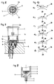
Fig. 1 zeigt einen Medianschnitt eines ersten Ausführungsbeispiels der erfindungsgemäßen Spannhülse 1 nebst der von ihr weitgehend formschlüssig umfaßten Steckdose 2. Die Spannhülse 1 weist eine Becherwandung 3 auf mit einem materialeinheitlich aus lichtleitendem Material angeformten Becherboden 4. Die Becherwandung 3 ist in Form eines geraden Hohlzylinders ausgebildet, wohingegen der Becherboden 4 im wesentlichen vollzylinderförmig ausgebildet ist, wobei der Becherboden 4 mittels einer Anschrägung 22 kegelstumpfförmig angeschrägt ist und wobei Becherwandung 3 und Becherboden 4 eine Kreisquerschnittsfläche aufweisen. Jedoch sind auch andere, z.B. elliptische Querschnittsflächen denkbar. Auf dem Boden der einen Haltekörper nebst Glühkopf (nicht abgebildet) aufnehmenden, ebenfalls becherförmig ausgebildeten Steckdose 2 ist ein erstes Pluspotentialkontaktteil 5 und ein Minuspotentialkontaktteil 7 angeordnet. Hierfür weist der Becherboden 4 eine ebenfalls kegelstumpfförmig ausgebildete Aufnahme 32 auf. Ein zweites Pluspotentialkontaktteil 6 (Fig.4,5) ist im Becherboden 4 der Spannhülse 1 ohne Durchgriff des Becherbodens 4 verrastet. Die Kontaktteile 5,7 durchgreifen im Becherboden 4 ausgeformte Ausnehmungen 12 (Fig.2). Sämtliche Kontaktteile 5,6,7 sind innerhalb eines von einer fiktiven Hohlzylindermantelfläche MF′ eines fiktiven Hohlzylinders umgrenzten Raumbereichs angeordnet. Hierbei schließt die fiktive Hohlzylindermantelfläche MF' in Steckdoseneinsteckrichtung an die Becherwandung 3 an, wobei der Außendurchmesser des fiktiven Hohlzylinders dem Außendurchmesser der Spannhülse 1 entspricht. Entlang einer Zentralachse ZA verläuft die Fügebewegung eines Montageroboters. Die Spannhülse 1 ist mit Hilfe von Klemmrippen 20, welche Anlaufschrägen 21 aufweisen, sicher hinter einem Armaturenbrett 18 verrastet. Die herausvergrößerte Detailansicht b) zeigt eine Variante der Klemmrippen 20 mit einer zusätzlichen Ablaufschräge 28. Eine hiermit korrespondierende Anschrägung am Armaturenbrett 18 unterstützt zusätzlich den Aufrastvorgang der Spannhülse 1.1 shows a median section of a first exemplary embodiment of the clamping
Die Fig. 2,3 zeigen weitere Seiten(schnitt)ansichten der erfindungsgemäßen Spannhülse 1 nach dem ersten Ausführungsbeispiel. In der Mantelfläche der Becherwandung 3 befinden sich erste Durchbrüche 13 für die im Betriebsfall auffedernden Bimetallfedern 15 der Steckdose 2. Der Beleuchtungs-Spannbecherhülse 1 inwändig angeformte Rastnasen 27 sind für deren Verrastung in der Steckdose 2 vorgesehen. Eine Lampenaufnahme 10 ist radial im Becherboden 4 eingeformt und lateral offen. Eine Lampe 9, vorzugsweise eine long-life-Lampe mit 10⁴ Stunden Brenndauer, kann hier eingefügt werden und mit Lampenanschlußdrähten 11 am zweiten Pluspotentialkontaktteil 6 sowie am Minuspotentialkontaktteil 7 leitend angeschlossen werden. Der Becherboden 4 weist eine kegelstumpfförmige Anschrägung 22 auf, welche das Einfügen der Spannhülse in das Armaturenbrett 18 erleichtert.FIGS. 2, 3 show further sides (sectional) views of the
Fig. 4 zeigt eine Aufsicht auf die Anordnung der Kontaktteile 5,6,7 des ersten Ausführungsbeispiels. Die Kontaktteile 6,7 sind über Lampenanschlußdrähte 11 mit der Lampe 9 verbunden. Das Minuspotentialkontaktteil 7 kontaktiert die Becherwandung der metallenen Steckdose 2, wohingegen über das erste Pluspotentialkontaktteil 5 Potential an die gegenüber der Steckdose 2 isoliert angeordneten Bimetallfedern 15 gelegt wird.Fig. 4 shows a plan view of the arrangement of the
Fig. 5 zeigt die Ausbildung der auf der Oberfläche der Becherwandung 3 ausgeformten Klemmrippen 20. Die Klemmrippen 20 sind in rotationssymmetrisch angeordneten Gruppen 24 von Klemmrippen 20 angeordnet. Jede Gruppe 24 weist unterschiedlich lange Klemmrippen 20 auf, wobei der Abstand des Endes einer Klemmrippe 20 zu einem an der Becherwandung 3 angeformten Leuchtring 19 mit der Wandstärke der Armaturenbretter 18 korrespondiert. Die Klemmrippen 20 können ein rechtwinkliges oder ein angeschrägtes Ende aufweisen, wie die Detailansichten zu Figur 1 zeigen. Anstelle der Klemmrippen 20 können auch eine oder mehrere Stahlfedern 17 hinter dem Armaturenbrett 18 ausfedern und die Becherwandung 3 verrasten, wie insbesondere Figur 2 zeigt. Selbstverständlich können auch alle einschlägig bekannten, hinsichtlich der sicheren Verrastung der Spannhülse 1 gleichwirkenden Befestigungsmittel (Gewinde, Kleber u.s.w.) vorgesehen werden.5 shows the design of the clamping
Fig. 6 zeigt einen Querschnitt durch die Spannhülse 1 nach der Schnittlinie VI-VI in Fig. 5. Zwischen der Steckdose 2 und der Becherwandung 3 sind Abstandsstege 29 und Hohlräume 16 vorgesehen, um eine Federwirkung der Klemmrippen 20 zu ermöglichen.FIG. 6 shows a cross section through the clamping
Fig. 7 zeigt die Seitenschnittansicht der erfindungsgemäßen Spannhülse 1 gemäß einem zweiten Ausführungsbeispiel, bei welchem die den Anschlußstecker 8 kontaktierenden Kontaktteile 5,7 als Koaxialanschluß ausgebildet sind. Bei Bedarf können weitere Kontaktteile koaxial angeordnet werden. Axial zentriert ist die Lampenaufnahme 10 für die Lampe 9 vorgesehen. Hierbei ist die Lampe 9 im Anschlußstecker 8 installiert, während der Ort größter Leuchtdichte im Zentrum des Becherbodens 4 liegt. Hierzu ist dem Becherboden 4 ein Ansatz 30 angeformt, der eine Schwalbenschwanzverrastung mit dem Material des Anschlußsteckers 8 bildet. Um eine Lichteinflutung in die Becherwandung 3 zu ermöglichen, müssen bei diesem Ausführungsbeispiel die als hohlzylinderförmige Ringkontakte ausgebildeten Kontaktteile 5,7 streifenförmige Lichtdurchtrittsschlitze 23 aufweisen, wie Fig. 8 zeigt.FIG. 7 shows the side sectional view of the clamping
Fig. 8 zeigt eine Aufsicht auf die koaxiale Anordnung der mit den Lichtdurchtrittsschlitzen 23 versehenen Kontaktteile 5,7 gemäß dem zweiten Ausführungsbeispiel in Figur 7.FIG. 8 shows a top view of the coaxial arrangement of the
Fig. 9 zeigt eine Seitenschnittansicht der erfindungsgemäßen Spannhülse 1 nach einem dritten Ausführungsbeispiel. Hierbei ist die Lampe 9 exzentrisch axial im Becherboden 4 angeordnet.Fig. 9 shows a side sectional view of the clamping
Fig. 10 a) bis f) zeigen verschiedene Querschnittsprofile 26 von Klemmrippen 20, die beim Aufschieben des Armaturenbretts 18 einfedern und hinter dem vollständig aufgeschobenen Armaturenbrett 18 auffedernd verrasten, wozu teilweise Hohlräume 16 und/oder Hinterschneidungen 31 vorgesehen sind.10 a) to f) show different
- 11
- SpannhülseAdapter sleeve
- 22nd
- Steckdosesocket
- 33rd
- BecherwandungCup wall
- 44th
- BecherbodenCup bottom
- 55
- 1. Pluspotentialkontaktteil1. Plus potential contact part
- 66
- 2. Pluspotentialkontaktteil2. Plus potential contact part
- 77
- MinuspotentialkontaktteilMinus potential contact part
- 88th
- AnschlußsteckerConnector
- 99
- Lampelamp
- 1010th
- LampenaufnahmeLamp holder
- 1111
- LampenanschlußdrähteLamp lead wires
- 1212th
- KontaktteilausnehmungenContact part recesses
- 1313
- 1. Durchbrüche in 31. Breakthroughs in 3
- 1414
- 2. Durchbrüche in 32. Breakthroughs in 3
- 1515
- Bimetallfedern von 2Bimetal springs from 2
- 1616
- HohlräumeCavities
- 1717th
- StahlfedernSteel springs
- 1818th
- Armaturenbrettdashboard
- 1919th
- LeuchtringIlluminated ring
- 2020th
- KlemmrippenClamping ribs
- 2121
- Anlaufschrägen von 20Sloping slopes of 20
- 2222
- Anschrägung von 4Bevel of 4
- 2323
- LichtdurchtrittsschlitzeLight transmission slits
- 2424th
- Gruppen von 20Groups of 20
- 2525th
- Duchbohrung von 5Through hole of 5
- 2626
- Querschnittsprofile von 20Cross-sectional profiles of 20
- 2727
- RastnasenLatches
- 2828
- AblaufschrägeRunoff slope
- 2929
- Abstandsstege an 3Spacer bars on 3
- 3030th
- Ansatz von 4Approach of 4
- 3131
- HinterschneidungenUndercuts
- 3232
- Aufnahmeadmission
- MF'MF '
- fiktive Hohlzylindermantelflächefictitious hollow cylinder surface
- ZAZA
- ZentralachseCentral axis
Claims (20)
- Electric cigar lighter which is to be installed more especially in the dashboard of a motor vehicle, the contact members of such lighter each comprising at least one positive potential contact member and one negative potential contact member and making contact with a connecting member disposed behind the front surface of the dashboard, the lighter having a socket which accommodates a retaining body together with an incandescent head, and a light-conducting clamping sleeve disposed between the socket and dashboard, the clamping sleeve having a light-transmitting ring at its front end and a lamp at its rear end and being adapted to accommodate the socket, characterised- in that the clamping sleeve (1) has a cup-shaped configuration with a cup wall (3) and a cup base (4);- in that all of the contact members (5, 6, 7), which are associated with one another at the connecting member end are disposed inwardly of an area which is defined by an imaginary surface (MF') of an imaginary hollow cylinder extending in the direction of insertion of the socket, said surface communicating with the cup wall (3), the external diameter of said hollow cylinder corresponding to the external diameter of the clamping sleeve (1);- and in that a lamp holder (10) is provided for the lamp (9) in the cup base (4).
- Electric cigar lighter according to claim 1, characterised in that the cup wall (3) has a hollow-cylindrical configuration, and the cup base (4) has a solid-cylindrical configuration.
- Electric cigar lighter according to claim 1 or 2, characterised in that the cup base (4) is inclined in a frustoconical manner by means of an inclined portion (22).
- Electric cigar lighter according to one of claims 1 to 3, characterised in that the first positive potential contact member (5) intersects the cup base (4) centrally or eccentrically, and in that the negative potential contact member (7) intersects the cup base (4) eccentrically, or vice versa.
- Electric cigar lighter according to claim 4, characterised in that the contact members (5, 7) are contact lugs and are associated with one another in a T-shaped manner.
- Electric cigar lighter according to one of the preceding claims, characterised in that a second positive potential contact member (6) intersects the cup base (4) eccentrically or is located in the cup base (4).
- Electric cigar lighter according to claim 6, characterised in that the contact members (5, 6, 7) are associated with one another in an I-shaped manner.
- Electric cigar lighter according to one of claims 4 or 6, characterised in that the contact members (5, 6, 7) are provided in the form of a coaxial connection.
- Electric cigar lighter according to claim 8, characterised in that the contact members (5, 6, 7) are hollow-cylindrical annular contacts having slots (23) which permit light to pass therethrough.
- Electric cigar lighter according to one of the preceding claims, characterised in that the lamp holder (10) is shaped eccentrically or centrally axially and is open at the connecting member end.
- Electric cigar lighter according to one of the preceding claims, characterised in that the lamp holder (10) is radially orientated in the wall of the cup base (4), and in that the first positive potential contact member (5), which is a contact lug and intersects the cup base (4) centrally, has a through-bore (25) corresponding to the diameter of the lamp (9).
- Electric cigar lighter according to one of the preceding claims, characterised in that the lamp connecting wires (11) are conductively connected, on the one hand, to the negative potential contact member (7) and, on the other hand, either to the first positive potential contact member (5) or to the second positive potential contact member (6).
- Electric cigar lighter according to one of the preceding claims, characterised in that securing means, more especially locking or clamping means, are provided on the external surface of the cup wall (3) facing the dashboard (18).
- Electric cigar lighter according to one of the preceding claims, characterised in that the external surface of the cup wall (3) is provided with clamping ribs (20).
- Electric cigar lighter according to one of the preceding claims, characterised in that the individual clamping ribs (20) have upward inclines (21) and/or downward inclines (28).
- Electric cigar lighter according to one of the preceding claims, characterised in that cross-sectional profiles (26) of the clamping ribs (20) are so resilient that the clamping ribs (20), corresponding to a particular dashboard thickness, spring inwardly initially while the dashboard (18) is being slipped thereover and spring upwardly so as to lock behind the slipped-over dashboard (18).
- Electric cigar lighter according to one of the preceding claims, characterised in that the clamping ribs (20) are orientated in an equidistant and axis-parallel manner.
- Electric cigar lighter according to one of the preceding claims, characterised in that spacer webs (29) and cavities (16) are provided between the socket (2) and the cup wall (3) in order to permit a spring action of the clamping ribs (20).
- Electric cigar lighter according to one of the preceding claims, characterised in that, instead of the clamping ribs (20), one or a plurality of steel springs (17) spring outwardly behind the dashboard and thus lock the cup sleeve (3).
- Electric cigar lighter according to one of the preceding claims, characterised in that the clamping ribs (20) are disposed in rotationally symmetrically arranged groups (24) of clamping ribs (20) having varying lengths or are integrally moulded, the spacing between the clamping ribs (20) with the same length from each group (24) and the rear end of the light-transmitting ring (19) corresponding to the particular wall thicknesses of different dashboards (18).
Applications Claiming Priority (2)
| Application Number | Priority Date | Filing Date | Title |
|---|---|---|---|
| DE3908617 | 1989-03-16 | ||
| DE3908617A DE3908617A1 (en) | 1989-03-16 | 1989-03-16 | AUTOMATICALLY MOUNTED AND ILLUMINATED ELECTRIC CIGAR LIGHTER |
Publications (3)
| Publication Number | Publication Date |
|---|---|
| EP0387773A2 EP0387773A2 (en) | 1990-09-19 |
| EP0387773A3 EP0387773A3 (en) | 1990-11-14 |
| EP0387773B1 true EP0387773B1 (en) | 1994-02-02 |
Family
ID=6376493
Family Applications (1)
| Application Number | Title | Priority Date | Filing Date |
|---|---|---|---|
| EP90104697A Expired - Lifetime EP0387773B1 (en) | 1989-03-16 | 1990-03-13 | Automatically fittable and illuminated electrical cigar lighter |
Country Status (3)
| Country | Link |
|---|---|
| US (1) | US5029048A (en) |
| EP (1) | EP0387773B1 (en) |
| DE (2) | DE3908617A1 (en) |
Families Citing this family (11)
| Publication number | Priority date | Publication date | Assignee | Title |
|---|---|---|---|---|
| DE10025000C5 (en) * | 2000-05-22 | 2013-01-31 | Witte & Sutor Gmbh | Plug-in light, in particular as a vehicle interior light |
| FR2663593B1 (en) * | 1990-06-21 | 1993-12-10 | Valeo Neiman | IGNITION BODY FOR CIGARETTE LIGHTERS, PARTICULARLY FOR MOTOR VEHICLES AND IGNITION BODY ASSEMBLY WITH LIGHTING RING COMPRISING SUCH AN IGNITION BODY. |
| DE4106322C2 (en) * | 1991-02-28 | 1996-02-15 | Schoeller & Co Elektrotech | Lighting device for an electric cigar lighter |
| DE4202120C2 (en) * | 1992-01-27 | 1995-04-13 | Schoeller & Co Elektrotech | Electric cigar lighter, in particular for motor vehicles |
| US5475577A (en) * | 1992-07-07 | 1995-12-12 | Donnelly Corporation | Accessory attachment plate for vehicle panels |
| FR2730461B1 (en) * | 1994-12-13 | 1997-04-04 | Valeo Vision | LIGHTING FIXING RING FOR CIGARETTE LIGHTERS, ESPECIALLY FOR MOTOR VEHICLES |
| FR2758111B1 (en) * | 1997-01-06 | 1999-03-05 | Valeo Vision | CIGARETTE LIGHTERS WITH LOCKING MEANS, PARTICULARLY FOR MOTOR VEHICLES |
| US6198272B1 (en) * | 1997-11-18 | 2001-03-06 | Lisle Corporation | Plug construction having positive and negative poles for circuit testing on vehicles |
| FR2801691B1 (en) * | 1999-11-30 | 2005-04-08 | Valeo Vision | DEVICE FOR CONTROLLING MULTIPLE STABLE POSITIONS, IN PARTICULAR FOR CIGAR LIGHTER |
| US20090034246A1 (en) * | 2007-07-30 | 2009-02-05 | John Alfred Ayres | Flashlight Assembly from Oil Type Lighters |
| US10759339B2 (en) * | 2016-08-15 | 2020-09-01 | Ford Global Technologies, Llc | Vehicle light system |
Family Cites Families (20)
| Publication number | Priority date | Publication date | Assignee | Title |
|---|---|---|---|---|
| US2506181A (en) * | 1946-03-22 | 1950-05-02 | Automatic Devices Corp | Illuminated cigar lighter |
| US2701297A (en) * | 1950-12-27 | 1955-02-01 | Casco Products Corp | Illuminated electric cigar lighter |
| GB767444A (en) * | 1954-05-18 | 1957-02-06 | Lawrence Edward Fenn | Improvements in or relating to electric cigarette lighters |
| US3424414A (en) * | 1966-11-03 | 1969-01-28 | Casco Products Corp | Cigar lighter receptacle |
| DE2203163C3 (en) * | 1972-01-24 | 1976-01-08 | Schoeller & Co, Elektrotechnische Fabrik, 6000 Frankfurt | Lighting device for cigar lighters, in particular for motor vehicles |
| DE2329040C3 (en) * | 1973-06-07 | 1978-06-22 | Gebr. Happich Gmbh, 5600 Wuppertal | Ashtrays, in particular for vehicles |
| DE7321282U (en) * | 1973-06-07 | 1973-10-11 | Gebr Happich Gmbh | ASCHER IN PARTICULAR FOR VEHICLES |
| DE7323648U (en) * | 1973-06-26 | 1973-10-11 | Schoeller & Co | ELECTRIC CIGAR LIGHTER |
| DE2535080C2 (en) * | 1975-08-06 | 1977-12-08 | Schoeller & Co, Elektrotechnische Fabrik Gmbh & Co, 6000 Frankfurt | Lighting device for cigar lighter |
| DE2652857C3 (en) * | 1976-11-20 | 1981-06-11 | Schoeller & Co Elektrotechnische Fabrik Gmbh & Co, 6000 Frankfurt | Electric cigar lighter with a bimetal switch designed as a snap disk |
| FR2436939B1 (en) * | 1978-09-19 | 1985-08-16 | Seima | LIGHTER |
| FR2436940A1 (en) * | 1978-09-19 | 1980-04-18 | Seima | Vehicle cigar lighter - has locking tab in cylinder engaged in slot by rotation |
| IT1108189B (en) * | 1978-12-19 | 1985-12-02 | Pramaggiore Luigi | REFINEMENTS IN CIGARETTE LIGHTERS, PARTICULARLY FOR VEHICLES |
| FR2446992A1 (en) * | 1979-01-22 | 1980-08-14 | Iao Industrie Riunite Spa | Vehicle cigarette or cigar lighter - fits into panel opening from front via radially deformable annular retaining element with ridged outer surface |
| IT7953065V0 (en) * | 1979-03-15 | 1979-03-15 | Iao Industrie Riunite Spa | CIGAR LIGHTER ESPECIALLY FOR MOTOR VEHICLES |
| IT1166499B (en) * | 1980-12-05 | 1987-05-06 | Iao Industrie Riunite Spa | ELECTRIC CIGARETTE LIGHTER FOR VEHICLES |
| JPS6086766U (en) * | 1983-11-16 | 1985-06-14 | ナイルス部品株式会社 | Car cigarette lighter |
| IT8553240V0 (en) * | 1985-04-16 | 1985-04-16 | Pramaggiore Luigi | ELECTRIC DEVICE FOR THE QUICK IGNITION OF CIGARS OR CIGARETTES ESPECIALLY FOR VEHICLES |
| US4713733A (en) * | 1987-03-25 | 1987-12-15 | Casco Products Corporation | Cigar lighter incorporating glow ring |
| DE8903941U1 (en) * | 1989-03-31 | 1989-07-27 | Schoeller & Co Elektrotechnische Fabrik Gmbh & Co, 6000 Frankfurt | Automatically mountable and illuminated electric cigar lighter |
-
1989
- 1989-03-16 DE DE3908617A patent/DE3908617A1/en active Granted
-
1990
- 1990-03-13 EP EP90104697A patent/EP0387773B1/en not_active Expired - Lifetime
- 1990-03-13 DE DE90104697T patent/DE59004455D1/en not_active Expired - Fee Related
- 1990-03-16 US US07/494,382 patent/US5029048A/en not_active Expired - Fee Related
Also Published As
| Publication number | Publication date |
|---|---|
| DE3908617C2 (en) | 1991-06-13 |
| DE3908617A1 (en) | 1990-09-27 |
| EP0387773A2 (en) | 1990-09-19 |
| DE59004455D1 (en) | 1994-03-17 |
| US5029048A (en) | 1991-07-02 |
| EP0387773A3 (en) | 1990-11-14 |
Similar Documents
| Publication | Publication Date | Title |
|---|---|---|
| EP0919074B1 (en) | Electrical connection | |
| EP2297561B1 (en) | Pre-installation assembly for a contact arrangement of a sensor assembly | |
| EP0387773B1 (en) | Automatically fittable and illuminated electrical cigar lighter | |
| DE102020130894A1 (en) | Module connector and contact protection element | |
| DE9200625U1 (en) | Connection cover for electric fuel pump | |
| EP1133813B1 (en) | Device for contacting an electric cable, especially a flat conductor cable | |
| EP2034562B1 (en) | Connector with an integrated insulating body | |
| DE3445326A1 (en) | ELECTRICAL CONNECTOR DEVICE FOR A CIGAR OR CIGARETTE LIGHTER | |
| WO2003030213A2 (en) | Headlamp bulb | |
| EP1503463B1 (en) | Insert socket | |
| EP0398063B1 (en) | Automatically mountable and illuminated electrical cigar lighter | |
| DE10237666B4 (en) | connector element | |
| DE8903941U1 (en) | Automatically mountable and illuminated electric cigar lighter | |
| EP3399599B1 (en) | Plug connector, connector and connector system | |
| DE3914892A1 (en) | Electric cigarette lighter incorporated in vehicle dashboard | |
| DE4211228C2 (en) | Adapter for a jack plug | |
| EP1610056B1 (en) | Connection device for detachably connecting a lamp | |
| EP4092330B1 (en) | Lamp socket with lamp retaining clip | |
| EP0139950B1 (en) | Lamp holder | |
| DE10065281A1 (en) | Electric motor with brush holder | |
| DE8616081U1 (en) | High frequency coaxial socket | |
| EP1171942A1 (en) | End shield for a commutator machine and a method for producing such an end shield | |
| DE102018100787B4 (en) | Rope holder for attaching an object to a rope | |
| EP0139882A1 (en) | Connection between armature coil ends and relative commutator segments | |
| DE202023100299U1 (en) | Electrical connector with integrated contact protection |
Legal Events
| Date | Code | Title | Description |
|---|---|---|---|
| PUAI | Public reference made under article 153(3) epc to a published international application that has entered the european phase |
Free format text: ORIGINAL CODE: 0009012 |
|
| AK | Designated contracting states |
Kind code of ref document: A2 Designated state(s): DE ES FR GB IT |
|
| PUAL | Search report despatched |
Free format text: ORIGINAL CODE: 0009013 |
|
| AK | Designated contracting states |
Kind code of ref document: A3 Designated state(s): DE ES FR GB IT |
|
| 17P | Request for examination filed |
Effective date: 19910220 |
|
| PGFP | Annual fee paid to national office [announced via postgrant information from national office to epo] |
Ref country code: LU Payment date: 19920903 Year of fee payment: 5 |
|
| EPTA | Lu: last paid annual fee | ||
| 17Q | First examination report despatched |
Effective date: 19930212 |
|
| GRAA | (expected) grant |
Free format text: ORIGINAL CODE: 0009210 |
|
| AK | Designated contracting states |
Kind code of ref document: B1 Designated state(s): DE ES FR GB IT |
|
| PG25 | Lapsed in a contracting state [announced via postgrant information from national office to epo] |
Ref country code: IT Free format text: LAPSE BECAUSE OF FAILURE TO SUBMIT A TRANSLATION OF THE DESCRIPTION OR TO PAY THE FEE WITHIN THE PRE;WARNING: LAPSES OF ITALIAN PATENTS WITH EFFECTIVE DATE BEFORE 2007 MAY HAVE OCCURRED AT ANY TIME BEFORE 2007. THE CORRECT EFFECTIVE DATE MAY BE DIFFERENT FROM THE ONE RECORDED.SCRIBED TIME-LIMIT Effective date: 19940202 Ref country code: GB Effective date: 19940202 Ref country code: FR Effective date: 19940202 Ref country code: ES Free format text: THE PATENT HAS BEEN ANNULLED BY A DECISION OF A NATIONAL AUTHORITY Effective date: 19940202 |
|
| REF | Corresponds to: |
Ref document number: 59004455 Country of ref document: DE Date of ref document: 19940317 |
|
| PGFP | Annual fee paid to national office [announced via postgrant information from national office to epo] |
Ref country code: GB Payment date: 19940322 Year of fee payment: 5 |
|
| PGFP | Annual fee paid to national office [announced via postgrant information from national office to epo] |
Ref country code: FR Payment date: 19940324 Year of fee payment: 5 |
|
| EN | Fr: translation not filed | ||
| GBV | Gb: ep patent (uk) treated as always having been void in accordance with gb section 77(7)/1977 [no translation filed] |
Effective date: 19940202 |
|
| PLBE | No opposition filed within time limit |
Free format text: ORIGINAL CODE: 0009261 |
|
| STAA | Information on the status of an ep patent application or granted ep patent |
Free format text: STATUS: NO OPPOSITION FILED WITHIN TIME LIMIT |
|
| 26N | No opposition filed | ||
| PGFP | Annual fee paid to national office [announced via postgrant information from national office to epo] |
Ref country code: DE Payment date: 19950310 Year of fee payment: 6 |
|
| PG25 | Lapsed in a contracting state [announced via postgrant information from national office to epo] |
Ref country code: DE Effective date: 19961203 |