EP3399599B1 - Plug connector, connector and connector system - Google Patents
Plug connector, connector and connector system Download PDFInfo
- Publication number
- EP3399599B1 EP3399599B1 EP18000234.7A EP18000234A EP3399599B1 EP 3399599 B1 EP3399599 B1 EP 3399599B1 EP 18000234 A EP18000234 A EP 18000234A EP 3399599 B1 EP3399599 B1 EP 3399599B1
- Authority
- EP
- European Patent Office
- Prior art keywords
- plug
- lance
- configuration
- sleeve
- plug connector
- Prior art date
- Legal status (The legal status is an assumption and is not a legal conclusion. Google has not performed a legal analysis and makes no representation as to the accuracy of the status listed.)
- Active
Links
Images


Classifications
-
- H—ELECTRICITY
- H01—ELECTRIC ELEMENTS
- H01R—ELECTRICALLY-CONDUCTIVE CONNECTIONS; STRUCTURAL ASSOCIATIONS OF A PLURALITY OF MUTUALLY-INSULATED ELECTRICAL CONNECTING ELEMENTS; COUPLING DEVICES; CURRENT COLLECTORS
- H01R13/00—Details of coupling devices of the kinds covered by groups H01R12/70 or H01R24/00 - H01R33/00
- H01R13/62—Means for facilitating engagement or disengagement of coupling parts or for holding them in engagement
- H01R13/627—Snap or like fastening
- H01R13/6275—Latching arms not integral with the housing
-
- H—ELECTRICITY
- H01—ELECTRIC ELEMENTS
- H01R—ELECTRICALLY-CONDUCTIVE CONNECTIONS; STRUCTURAL ASSOCIATIONS OF A PLURALITY OF MUTUALLY-INSULATED ELECTRICAL CONNECTING ELEMENTS; COUPLING DEVICES; CURRENT COLLECTORS
- H01R13/00—Details of coupling devices of the kinds covered by groups H01R12/70 or H01R24/00 - H01R33/00
- H01R13/62—Means for facilitating engagement or disengagement of coupling parts or for holding them in engagement
- H01R13/627—Snap or like fastening
- H01R13/6277—Snap or like fastening comprising annular latching means, e.g. ring snapping in an annular groove
-
- H—ELECTRICITY
- H01—ELECTRIC ELEMENTS
- H01R—ELECTRICALLY-CONDUCTIVE CONNECTIONS; STRUCTURAL ASSOCIATIONS OF A PLURALITY OF MUTUALLY-INSULATED ELECTRICAL CONNECTING ELEMENTS; COUPLING DEVICES; CURRENT COLLECTORS
- H01R13/00—Details of coupling devices of the kinds covered by groups H01R12/70 or H01R24/00 - H01R33/00
- H01R13/62—Means for facilitating engagement or disengagement of coupling parts or for holding them in engagement
- H01R13/639—Additional means for holding or locking coupling parts together, after engagement, e.g. separate keylock, retainer strap
-
- H—ELECTRICITY
- H01—ELECTRIC ELEMENTS
- H01R—ELECTRICALLY-CONDUCTIVE CONNECTIONS; STRUCTURAL ASSOCIATIONS OF A PLURALITY OF MUTUALLY-INSULATED ELECTRICAL CONNECTING ELEMENTS; COUPLING DEVICES; CURRENT COLLECTORS
- H01R13/00—Details of coupling devices of the kinds covered by groups H01R12/70 or H01R24/00 - H01R33/00
- H01R13/46—Bases; Cases
- H01R13/502—Bases; Cases composed of different pieces
- H01R13/506—Bases; Cases composed of different pieces assembled by snap action of the parts
Definitions
- the invention relates to a connector system comprising a connector, in particular a push-pull connector, and a plug for such a connector.
- connector systems for separating or connecting two line sections which are formed for carrying an electrical current and / or for transmitting electronic signals.
- the individual connectors of these connector systems have connecting sections which can be coupled by means of a form fit and / or a force fit and which, in particular when used in devices that require the connection to be secured against unintentional loosening, such as when used in industrial systems or in a motor vehicle, by means of a screw connection can be secured.
- push-pull connector systems in which the connector system is coupled without the provision of a thread or a nut. The problem is that only one of the different types of systems can be used in each case, since the conventional connector systems are incompatible with one another.
- EP 1 115 179 A2 discloses a multi-toothed locking ring for a rotary coupling system which traverses a thread of a complementary half of the rotary coupling system in the axial direction and engages on the external thread of the complementary half.
- EP 0 881 713 A1 discloses a lockable electrical connector having at least one contact-carrying first part and at least one contact-carrying second part, each part having a housing in which the corresponding contact is held by insulating material, the housing of the second part on the housing of the first Part can be plugged in and to lock the second part on the first part at the end of the mating process, the housing of the two parts carries a movable ring.
- EP 1 672 751 A1 discloses a socket for compact fluorescent lamps with bases of the types G23 or G24 with a socket housing part made of insulating material containing electrical contacts, with locking springs arranged in the socket housing part engaging behind the locking lugs present on the lamp socket for locking the lamp socket.
- the object of the present invention is to provide an improved connector, a plug for such a connector and a connector system.
- a connector system according to claim 1 is provided.
- the connector according to the invention is suitable for separating or connecting two current-carrying line sections in devices that require the use of vibration-proof connections or connections secured against unintentional loosening during operation of the device due to vibrations and / or frequent relative movements of individual components against each other, and which nevertheless quickly and should be easy to solve.
- plug connectors and / or plugs can have a connection contact.
- the plug connector and / or the plug can have an insulating body or a plug insulating body, in which the connection contacts can be arranged.
- the insulation body or plug insulation body can have a plurality of essentially cylindrical insulation body recesses which extend in the axial direction through the insulation body or plug insulation body.
- the connection contacts which can each have a stranded wire connection section, can be arranged in the insulation body recesses.
- the strand connection sections can each be connectable to the electrical lines or the individual strands of a respectively assigned electrically conductive cable.
- the strand connection sections are each connected to an associated strand, for example by soldering or clamping the strand to the strand connection section.
- the number of connection contacts of a connector or plug is not limited, and can be, for example, 2 to 8 or more.
- connection contacts also each have a contacting section, wherein the contacting section can be designed as a female or a male variant.
- the connection contacts of the plug are preferably each formed as a male contact section, the male contact section being designed in such a way that it can be inserted into a female contact section.
- the connection contacts of the plug connector are preferably each formed as a female contacting section, the female contacting section being designed such that it can accommodate a complementary male contacting section.
- the female connector can also be referred to as a socket. If contact is established between the preferably male contacting sections of the plug and the preferably female contacting sections of the plug connector, the plug and the plug connector are connected in an electrically conductive manner.
- the male contacting sections of the complementary plug are pushed in a plugging direction into the female contacting sections of the plug connector, the plugging direction resulting from a directed movement of the plug and plug connector along their axial extent to one another.
- the receiving area of the connector can in particular be defined by the movable sleeve element and the at least one lance, the sleeve element at least partially enclosing the lance.
- the sleeve element can be movable in the axial and / or in the radial direction relative to the lance. Instead of a single lance, a plurality of lances can be provided which are at least partially enclosed by the sleeve element.
- the lance extends with its longitudinal dimension along the longitudinal axis of the sleeve element and has a latching hook which can undercut a holding configuration formed on the complementary plug in such a way that the Connection of connector and plug is held positively in the plug position.
- the latching hook can extend at least radially inward from the lance, the holding configuration of the plug then extending radially outward from the plug, so that the latching hook can undercut the holding configuration.
- the term undercutting can in principle also mean reaching behind or hooking or hooking behind. In other words, the terms “undercut”, “gripping behind”, “rear hook” or “hooking in” can be used synonymously in this application.
- the plug can have several holding configurations, in particular one per lance.
- the latching hook of the lance and / or the holding configuration of the plug can each be formed with a slope so that the latching hook can slide past the holding configuration with little resistance during an insertion movement.
- the lance is elastically displaceable in particular while the latching hook slides past the holding configuration and springs back after sliding past, as a result of which the latching hook can latch in a form-fitting manner behind the holding configuration. Since the lance can be moved outwards, various external profiles can be formed on the plug without hindering the connection of the plug connector and plug.
- the sleeve element can have a lifting configuration per lance, which can interact with a displacement configuration formed on each lance such that the lance can be displaced radially outward when the sleeve element moves relative to the lance.
- the radial displacement here means a movement of the lance in a radial direction, that is to say along an imaginary axis of symmetry through the connector that extends orthogonally to the length.
- the term “outward” denotes the direction of movement of the lance during the elastic displacement in relation to the receiving area, viewed in a radial cross section, the receiving area representing an inner area. So the lance shifts in Outward direction, away from the shooting area.
- the sleeve element can be moved relative to the lance in such a way that the lifting configuration of the sleeve element is approximately congruent with the displacement configuration of the lance, whereby the lance is displaced elastically outward in the radial direction.
- the displacement configuration and / or the lifting configuration can each have a slope. As a result, the displacement configuration and the lifting configuration slide with a relative movement along the inclines and the relative movement can be carried out with little and approximately constant expenditure of force.
- the plug is free of the form-fitting connection between the locking hook of the lance and the holding configuration of the plug and the connection area of the plug can be pulled out of the receiving area of the plug connector, whereby the electrically conductive connection can be separated.
- At least one limiting section can also be formed on the connector, which limits a relative movement of the sleeve element to the lance in such a way that, during the relative movement, the lifting configuration of the sleeve element cannot be moved beyond a provided position on or beyond the displacement configuration of the lance.
- the relative movement of the sleeve element can, depending on the embodiment, take place either in the axial direction relative to the lance or in a radial rotary movement relative to the lance.
- the bevels on the displacement configuration of the lance and / or on the lifting configuration of the sleeve element can be provided in accordance with the intended relative movement.
- the sleeve element is preferably essentially cylindrical and extends coaxially with the plug connector or the insulation body.
- the sleeve element can be coupled to the plug connector or the insulation body via the lance or the lances, in particular it can be coupled to the plug connector or the insulation body exclusively via the lance or the lances.
- the sleeve element has a sleeve ring lying radially on the inside and the lifting configuration is formed on the sleeve ring.
- the sleeve ring of the sleeve element can advantageously be manufactured inexpensively by means of various manufacturing processes.
- the sleeve element can be formed in one piece with the sleeve ring by means of an injection molding process, or the sleeve element and sleeve ring are formed in several pieces, with the sleeve element being connected to the sleeve ring by subsequent joining, for example by gluing, pressing or welding.
- the sleeve element formed in this way with a radially inner sleeve ring moves the sleeve ring and thus the lifting configuration when the sleeve element moves relative to the lance, whereby the lifting configuration can engage the displacement configuration when the sleeve element moves relative to the lance.
- the sleeve ring preferably has at least one recess, and the lance extends through the recess in such a way that the lifting configuration is arranged radially on the inside of the lance, and by means of a relative movement of the sleeve element to the lance, the lifting configuration engages with the displacement configuration, whereby the lance is elastically displaceable radially outward.
- the recess can be formed on the sleeve ring radially on the outside and open radially outwards, whereby the lance can be displaced elastically radially outwards. This ensures that the lance can be displaced without hindrance will.
- the sleeve ring can otherwise be connected to the sleeve element at the remaining sections.
- the number of recesses in the sleeve ring can correspond to the number of lances, with one lance each being able to be arranged in a recess.
- the latching hooks of the plurality of lances can be released simultaneously from the holding configurations of the plug, whereby the plug can be unlocked and removed in one working step.
- the sleeve element and the sleeve ring are preferably separate components.
- the sleeve ring can be arranged in the sleeve element.
- the sleeve element and the sleeve ring can each be formed as one-piece components.
- the sleeve element and the sleeve ring can also be designed as a multi-part component. If the sleeve ring is arranged in the sleeve element, a two-part sleeve assembly is formed. In particular, casting, milling or injection molding can be used as a method for producing the sleeve element and the sleeve ring.
- the latching hook and the displacement configuration preferably point in the same radial direction. Consequently, the latching hook and the displacement configuration can point either together or at the same time in the radial direction inward or in the radial direction outward.
- the sleeve element can have at least one radially inwardly deformed lance passage area, the lance passage area extending in the axial direction along a section of the sleeve element, and wherein the lance passage area has a recess and the lance thus extends through the recess along the radially inwardly deformed lance passage area that the lifting configuration is arranged radially on the inside of the lance, and by means of a relative movement of the Sleeve element for the lance, the lifting configuration engages with the displacement configuration, whereby the lance is elastically displaceable radially outward.
- the radially inwardly deformed lance passage area of the sleeve element can extend in some areas in the direction of the longitudinal axis of the sleeve element and have a depth at which the lance can extend from the passage of the lance through the recess along the radially inwardly deformed lance passage area.
- the lifting configuration can be formed on a suitable section of the lance passage area as a structure extending radially outward from the sleeve element or the lance passage area.
- the suitable section means in particular the section of the lance passage area which is located in the axial direction, i.e. in the direction of the longitudinal axis of the sleeve element, approximately at the level of the displacement configuration of the lance.
- the displacement configuration can point or protrude inward in the radial direction.
- the lifting configuration can come into engagement with the displacement configuration, whereby the lance can be displaced elastically radially outward.
- the sleeve element can also be produced in this way without the provision of a sleeve ring, the lifting configuration being formed in a cost-effective manner by providing the inwardly deformed lance passage area with the recess.
- the connector preferably has a plurality of lances, the lances being formed on a carrier element and the displacement configurations of the lances in each case interacting with the lifting configuration of the sleeve elements in such a way that when the sleeve element moves relative to the plurality of lances, the lances simultaneously radially outward are elastically displaceable.
- the carrier element can be ring-shaped and / or sleeve-shaped and forms the base for the lance or preferably the plurality of lances.
- the lances extend axially forward in a starting from the carrier element Insertion direction of the connector, which runs opposite to an insertion direction of the connector.
- a plurality of lances can be produced in one piece together with the carrier element, for example as a turned part or by means of an injection molding process, which results in inexpensive production and simple assembly in the connector.
- the carrier element for example as a turned part or by means of an injection molding process, which results in inexpensive production and simple assembly in the connector.
- no further supports for the majority of lances need to be provided on the connector.
- the lances are preferably spaced apart from one another at regular angular intervals.
- the receptacle area of the connector is formed with a uniform distribution of lances, so that when the connector is electrically connected to the complementary plug, insufficient electrical contact between individual, complementary connection contacts of the plug connector and plug is avoided.
- the latching hook and the displacement configuration preferably extend radially inward from the lance.
- the lance can be elastically displaced radially outward, whereby the positive connection between the latching hook and the holding configuration can be released by means of one work step, the connector having a smooth profile on the outside.
- the connector therefore advantageously takes up little space.
- the latching hook and / or the displacement configuration preferably have an inclined section.
- the lance therefore slides advantageously with little resistance along the lifting configuration of the sleeve element and along the holding configuration of the plug, overcoming the elastic deformation of the Lance, whereby the plug can be connected to the connector without great effort.
- a plug for the connector system wherein the plug has a connection area with a thread and a holding configuration, and wherein the thread has at least one axially extending lowered area, wherein on the rear portion of the connector in the plugging direction of the lowered area, the holding configuration is formed, wherein in a plugged position of the plug and the connector the lance is arranged in the lowered area such that the holding configuration of the plug is undercut by the latching hook of the at least one lance.
- the plug can have a plug insulation body, wherein the plug insulation body can have a plurality of essentially cylindrical insulation body recesses which extend in the axial direction through the plug insulation body. Terminal contacts can be arranged in the insulation body recesses, each of which has a strand connection section.
- the strand connection sections can each be connectable to the electrical lines or the individual strands of a respectively assigned electrically conductive cable. In order to produce such an electrically conductive connection, the strand connection sections can each be connected to an associated strand, for example by soldering or clamping the strand to the strand connection section.
- connection contacts also each have a contacting section, wherein the contacting section can be designed as a female or a male variant.
- the connection contacts of the plug are preferably each formed as a male contacting section, the male contacting section being designed such that it can be inserted into the preferably female contacting section of the plug connector.
- the thread of the plug can have a plurality of recessed areas, which can be approximately strip-shaped, the recessed areas extending from the holding configuration, starting in the plugging direction or in the axial direction.
- the recessed areas can be produced, for example, by means of milling and can be designed as a flattened residual thread or completely without a thread.
- the lowered areas can also be referred to as thread recesses.
- the recessed areas can be formed along the periphery of the connection area in the areas which, in the mating position, correspond to the areas of the lances and the lifting configurations of the connector.
- the plug preferably has three recessed areas. The lowered areas can have different widths in the circumferential direction.
- a lowered area can be wider in the circumferential direction, while the other lowered areas have a — preferably identical — narrow dimension in the circumferential direction.
- the wider, recessed area can serve as a visual orientation aid which, in order to connect correctly to the connector, must be aligned with an orientation marking or orientation recess of the connector.
- one of the lances and / or the lifting configurations of the plug connector can be made wider in the circumferential direction than the remaining lances or lifting configurations, so that the plug can only be inserted into the plug connector correctly aligned with the plug connector.
- the plug With correct alignment, the plug can be guided in its plugging movement towards the plug connector through the interaction of the lowered areas with the lances or lifting configurations to the plugging position before it reaches the plugging position.
- the lowered area or the lowered areas are flanked, in particular, in the circumferential direction by threaded sections.
- the threaded sections allow the connector to be screwed to the connector by means of a fastening nut.
- the plug for arranging a plurality of lances can have a plurality of lowered areas or threaded sections, the plug can be screwed into a conventional complementary screw connector with an internal thread by means of the thread.
- the plug is therefore advantageous both for conventional connectors with an internal thread and for the Connector according to one aspect of the present invention is provided.
- the thread preferably has a plurality of depressed areas, and one depressed area has a dimension that is wider in the circumferential direction than the other depressed areas.
- a plug-in movement from the plug into the plug-in connector can position from plug-to-plug connector from the first contact from Snap hooks or lifting configuration to the lowered area.
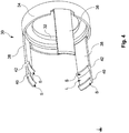
- Fig. 1 shows a perspective exploded view of a plug connector 10 according to an embodiment, comprising a cable 12 with in the present case five strands 14 thereof.
- the cable 12 or the strands 14 are formed for carrying an electrical current and / or for transmitting electronic signals.
- the strands 14 are each connected to a strand connection section of a connection contact AK of an insulation body 16, the insulation body 16 having a plurality of the connection contacts AK.
- the insulation body 16 has a plurality of essentially cylindrical insulation body recesses which extend in the axial direction through the insulation body.
- the connection contacts AK are arranged in each of these insulation body recesses.
- the insulation body 16 has five connection contacts AK, which can each be contacted via the end faces 20a, 20b.
- the insulation body 16 essentially has a cylindrical shape and is formed from a non-conductive material, in the present case from thermoplastic polyurethane (TPU).
- TPU thermoplastic polyurethane
- the insulation body 16 can, however, also be formed from another suitable plastic.
- the connection of the individual strands 14 to the respective strand connection section is formed in the present case by means of soldering.
- the protective sleeve 26 is connected to the end section 22 and the rear end section 24 by means of extrusion coating, wherein this extrusion coating can be the last work step in the assembly of the connector 10.
- the protective sleeve 26 is formed from a non-conductive material, in the present case from thermoplastic polyurethane (TPU).
- TPU thermoplastic polyurethane
- the cable 12 or the strands 14 thereof are connected with the non-free end to an electronic component or an electronic device.
- On the insulation body 16 is between the Face 20a and face 20b a flange ring 28 is formed on the insulation body 16 is between the Face 20a and face 20b a flange ring 28 is formed.
- the flange ring 28 is approximately in the middle between the two end faces 20a, 20b, but at a distance from the rear end section 24 or from the protective sleeve 26 (see FIG Fig. 3 ), arranged.
- the plug connector 10 further has a carrier element 30, the carrier element 30 being pushed in the axial direction 18 from the end face 20b onto the insulation body 16.
- the carrier element 30 is formed as a carrier ring 32 with a carrier wall 34 lying radially on the outside of the carrier ring 32 (see also FIG Fig. 4 ).
- the arrow 36 shows the radial direction, the center of an area enclosed by the carrier ring 32 representing the innermost point when viewed in a radial plan view.
- the carrier ring 32 has a centrally arranged opening that fits precisely to the rear end section 24 and is connected to an end face of the flange ring 28 by means of a joining process, in this case pressing, with an end face facing the flange ring 28, the end face of the flange ring 28 being that face , which in turn faces the carrier ring 32.
- a plurality of lances 38 is formed on the support wall 34 of the support element 30, more precisely it is three lances 38.
- the support element 30 is produced in one piece as a turned part.
- the lances 38 extend axially from the support wall 34 in the plug-in direction of the plug connector SR SV and are arranged radially on the outside of the support ring 32, whereby the lances are spaced apart from the insulation body 16 by the radial width of the support ring 32.
- the lances 38 are also spaced apart from one another on the carrier ring 32 by the same angular distance, in the present case 120 degrees.
- the carrier element 30 is made of a metal such as brass or a spring steel.
- the lances 38 are elastically displaceable radially outward and each have a latching hook 40 and a displacement configuration 42.
- the locking hook 40 and the displacement configuration 42 are rigid and essentially non-elastically deformable.
- the latching hook 40 and the displacement configuration 42 extend radially inward from the lance 38 and each have a ramp-like shape with a slope S.
- the latching hook 40 is formed for undercutting an associated holding configuration 44, likewise including a bevel S, of a complementary plug 46 (see FIG Fig. 7 and 8th ), whereby in a plug-in position of the complementary plug 46 with the plug connector 10, the plug connector system, which comprises the plug 46 and the plug connector 10, is in the present case positively connected.
- the plug 46 and plug connector 10 are pushed together in the axial direction 18, the bevels S of the latching hook 40 and the holding configuration 44 being able to slide on one another, whereby the lance 38 can be displaced elastically radially outward.
- the latching hook 40 has passed the incline S of the holding configuration 44, the lance 38 moves back into the original position and the latching hook 40 latches behind the holding configuration 44.
- the carrier element 30 is surrounded by a sleeve element 48, the sleeve element 48 being essentially formed as a hollow cylinder, the longitudinal extent of which is arranged along the axial direction 18.
- the sleeve element 48 consequently also surrounds the region of the insulation body 16 which is surrounded by the carrier element 30.
- the sleeve element is produced from zinc by means of a die-casting process and has, in sections, a circumferential corrugation R, on which the sleeve element 48 can be gripped in a non-slip manner.
- the corrugation R can be formed from a rubber coating arranged on the sleeve element 48.
- the corrugation R also has an orientation recess which enables the plug to be placed on the connector in a precisely positioned manner.
- a sleeve ring 50 is formed on the sleeve element 48 radially on the inside and essentially at the end (see also Fig. 6 and 8th ).
- the sleeve element 48 and the sleeve ring 50 form a sleeve assembly 64 (see Fig. 6 ).
- the sleeve ring 50 is made as a separate component, ie as an independent component by means of an injection molding process from a plastic or by means of machining from a metal and pressed with the hollow cylinder by means of press fitting.
- the sleeve ring 50 in the present case has three lifting configurations 52, one lifting configuration 52 per lance 38.
- the lifting configuration 52 is formed as a recessed section of the sleeve ring 50 and can each come into engagement with the displacement configuration 42 of an associated lance 38.
- the sleeve ring 50 is formed in the area of the lifting configuration 52 with a recess 54, in which the lance 38 is arranged with an intermediate lance section L arranged between the latching hook 40 and the displacement configuration 42, whereby the lifting configuration 52 is arranged radially on the inside of the lance 38.
- the sleeve element 48 and the sleeve ring 50 formed thereon are movable in the axial direction 18 relative to the lance 38, so that by means of a relative movement of the sleeve element 48 or the sleeve assembly 64 to the lance 38 in the plug-in direction of the plug SR S, the lifting configuration 52 with the displacement configuration 42 in Engagement occurs, whereby the lance 38 is elastically displaced radially outward.
- a distance A is provided between the protective sleeve 26 and the flange ring 28 or the carrier ring 32 arranged on the flange ring 28 (see Fig. 3 ).
- the sleeve element 48 can also be designed with a shape that can surround the protective sleeve 26, so that no distance A has to be provided.
- the engagement between the lifting configuration 52 and the displacement configuration 42 takes place in such a way that due to the axial relative movement of the sleeve element 48 or the sleeve assembly 64 to the lance 38, the lifting configuration 52 slides along the slope S of the displacement configuration 42 and thereby the lance 38 slides radially outward relocated.
- the sleeve element is radial in the insertion direction SR SV expanding inside
- the lifting configuration 52 slides back along the displacement configuration 42 into the original position, namely to the position at which the lance intermediate section L is arranged between the latching hook 40 and the displacement configuration 42 is, whereby the lance 38 is no longer displaced.
- the carrier element 30 is designed with three lances 38 and the sleeve ring 50 has three recesses 54 or three lifting configurations 52, ie one per lance 38, the relative movement of the sleeve element 48 or the sleeve assembly 64 to the lance 38 in the direction of the end face 20b, all three lances 38 can be elastically displaced radially outward at the same time. As a result, a hook behind the holding configurations 44 of the complementary plug 46 can be released by the latching hook 40 of the lance 38, as a result of which the plug 46 can be separated from the plug connector 10.
- the plug connector is formed as a female part of the plug connector system, ie the plug connector has the female connection contacts AK, which are formed for receiving the male connection contacts of the plug 46.
- the connector 10 can also be designed as a male part of the connector system.
- a molded seal 56 is arranged on an area of the flange ring 28, which ensures a flush connection between the plug 46 and the plug connector 10.
- Fig. 2 shows the assembled state of the plug connector 10 in a perspective view.
- the connection contacts AK which are formed to accommodate the current-carrying connection contacts of the plug 46, are arranged on the end face 20a of the insulating body 16.
- Fig. 3 shows a side view of the connector 10, from which the arrangement of the sleeve element 48 in relation to the protective sleeve 26 with a distance A can be seen.
- the sleeve element 48 is for unlocking a connection between plug 46 and plug connector 10 (not shown here) in the direction of the protective sleeve 26 displaceable by the distance A, as a result of which the lances 38 enclosed by the sleeve element 48 can move elastically radially outward, so that a rear hook of the holding configuration 44 of the plug 46 can be released by the latching hook 40 in the plug-in position.
- the corrugation R is used for comfortable and slip-proof gripping of the protective sleeve.
- Fig. 4 shows in detail the carrier element 30 on whose carrier wall 34 the lances 38 are formed.
- the latching hooks 40 and the displacement configurations 42 are formed on the end section in the insertion direction SR SV of the lances 38 (see FIG Fig. 1 ).
- the lance intermediate section L on which the lifting configuration 52 and the recess 54 of the sleeve ring 50 are arranged lies between the latching hooks 40 and the displacement configurations 42.
- the locking hooks 40 and the displacement configurations 42 each have the slope S, the slope S of the locking hook not having to run at the same angle to the lance 38 as the slope S of the displacement configurations 42.
- the respective slopes of different embodiments can be different.
- Fig. 5 shows the carrier element 30 with the sleeve ring 50 arranged thereon, the sleeve ring 50 with the lifting configuration 52 being arranged in the area of the lance intermediate section L.
- the lances 38 are in a non-displaced state. If the sleeve ring 50 is displaced in the insertion direction SR S by means of a movement of the sleeve element 48 (see FIG Fig. 1 ), the lifting configurations 52 each press on the slope S of the displacement configurations 42 (see FIG Fig. 4 , here covered by the lifting configuration 52), whereby the lances 38 are increasingly elastically displaced radially outward. If the lifting configuration 52 glides back along the bevels S to the intermediate lance sections L, the lances shift back into their original position.
- FIG. 14 is a perspective view of the sleeve assembly 64, with FIG In the present embodiment, the sleeve assembly 64 comprises the sleeve element 48 and the sleeve ring 50.
- the sleeve ring 50 has a recess 54 in each of its lifting configurations 52, whereby the lifting configuration 52 is spaced from the hollow cylindrical body of the sleeve element 48 such that the lance 38 can be arranged between the sleeve element 48 and the lifting configuration 52.
- the number of recesses 54 corresponds in the present case to the number of lances 38, namely three.
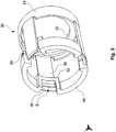
- Fig. 7 shows a perspective view of a plug 46.
- the plug 46 is formed in the present case as a male connector, ie the plug 46 is formed with its male connection contacts for insertion into the female connection contacts AK of the connector 10, and has a cable (not shown) with five in the present case Line contacts or strands (not shown) thereof.
- the cable or the strands are formed for carrying an electrical current and / or transmitting electronic signals.
- the strands are each connected to a connection contact (not shown) of a plug insulation body (not shown).
- the plug insulation body essentially has a cylindrical shape and is made of a non-conductive material, in this case thermoplastic polyurethane (TPU).
- TPU thermoplastic polyurethane
- the plug 46 has a radially outer thread 58, the thread 58 having a plurality of axially extending lowered areas 60, a holding configuration 44 also being formed on the rear sections of the lowered areas 60 in the plug-in direction of the plug connector 10.
- lances 38 extend along lowered areas 60 up to holding configuration 44 and undercut holding configuration 44 with latching hooks 40.
- a lowered area 60 is provided on plug 46 for each lance 38 .
- the lowered areas 60 can be produced by milling out the thread 58.
- the holding configuration 44 has a bevel S on which the bevel S of the latching hook 40 can slide, as a result of which the lance 38 is elastically displaced radially outward until the latching hook 40 engages behind the holding configuration 44 and undercuts the holding configuration 44.
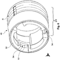
- Fig. 8 shows the connector system comprising the plug 46 and the plug connector 10 in the separated state, the arrow 62 showing the plug direction in which the plug 46 can be pushed into the plug connector to establish an electrically conductive connection.
Description
Die Erfindung betrifft ein Steckverbindersystem aufweisend einen Steckverbinder, insbesondere ein Push-Pull-Steckverbinder, und einen Stecker für einen solchen Steckverbinder.The invention relates to a connector system comprising a connector, in particular a push-pull connector, and a plug for such a connector.
Zum Trennen oder Verbinden zweier Leitungsabschnitte, die zum Führen eines elektrischen Stroms und/oder Übertragen von elektronischen Signalen gebildet sind, ist es bekannt Steckverbindersysteme einzusetzen. Die einzelnen Steckverbinder dieser Steckverbindersysteme weisen Verbindungsabschnitte auf, die mittels eines Formschlusses und/oder eines Kraftschlusses koppelbar sind und die insbesondere beim Einsatz in Vorrichtungen die ein Sichern der Verbindung gegen unbeabsichtigtes Lösen erfordern, wie etwa beim Einsatz in industriellen Anlagen oder in einem Kraftfahrzeug, mittels einer Verschraubung sicherbar sind. Darüber hinaus gibt es sogenannte Push-Pull-Stecksysteme bei denen ohne das Vorsehen eines Gewindes bzw. einer Mutter ein Koppeln des Stecksystems erreicht wird. Problematisch ist, dass lediglich nur jeweils eines der verschiedenartigen Systeme Anwendung finden kann, da die herkömmlichen Steckverbindersysteme untereinander inkompatibel sind.It is known to use connector systems for separating or connecting two line sections which are formed for carrying an electrical current and / or for transmitting electronic signals. The individual connectors of these connector systems have connecting sections which can be coupled by means of a form fit and / or a force fit and which, in particular when used in devices that require the connection to be secured against unintentional loosening, such as when used in industrial systems or in a motor vehicle, by means of a screw connection can be secured. In addition, there are so-called push-pull connector systems in which the connector system is coupled without the provision of a thread or a nut. The problem is that only one of the different types of systems can be used in each case, since the conventional connector systems are incompatible with one another.
Aufgabe der vorliegenden Erfindung ist es, einen verbesserten Steckverbinder, einen Stecker für einen solchen Steckverbinder und ein Steckverbindersystem bereitzustellen.The object of the present invention is to provide an improved connector, a plug for such a connector and a connector system.
Gemäß einem Aspekt der Erfindung wird ein Steckverbindersystem nach Anspruch 1 bereitgestellt.According to one aspect of the invention, a connector system according to claim 1 is provided.
Vorteilhafterweise ist der erfindungsgemäße Steckverbinder zum Trennen oder Verbinden zweier stromführender Leitungsabschnitte in Vorrichtungen geeignet, die im Betrieb der Vorrichtung aufgrund von entstehenden Vibrationen und/oder häufiger Relativbewegungen einzelner Bauelemente gegeneinander den Einsatz von vibrationsfesten bzw. gegen ein unbeabsichtigtes Lösen gesicherter Verbindungen erfordern und die dennoch schnell und einfach lösbar sein sollen.Advantageously, the connector according to the invention is suitable for separating or connecting two current-carrying line sections in devices that require the use of vibration-proof connections or connections secured against unintentional loosening during operation of the device due to vibrations and / or frequent relative movements of individual components against each other, and which nevertheless quickly and should be easy to solve.
Zum Herstellen einer elektrisch leitenden Verbindung zwischen dem Steckverbinder und dem komplementären Stecker können Steckverbinder und/oder Stecker einen Anschlusskontakt aufweisen. Der Steckverbinder und/oder der Stecker können einen Isolationskörper bzw. einen Steckerisolationskörper aufweisen, in dem die Anschlusskontakte angeordnet sein können. Der Isolationskörper bzw. Steckerisolationskörper kann mehrere im Wesentlichen zylindrische Isolationskörperausnehmungen aufweisen, die sich in axialer Richtung durch den Isolationskörper bzw. Steckerisolationskörper erstrecken. In den Isolationskörperausnehmungen können die Anschlusskontakte angeordnet sein, die jeweils einen Litzenverbindungsabschnitt aufweisen können. Die Litzenverbindungsabschnitte können jeweils mit den elektrischen Leitungen bzw. den einzelnen Litzen eines jeweils zugeordneten elektrisch leitenden Kabels verbindbar sein. Zum Herstellen einer solchen elektrisch leitenden Verbindung werden die Litzenverbindungsabschnitte jeweils mit einer zugeordneten Litze verbunden, etwa mittels verlöten oder verklemmen der Litze mit dem Litzenverbindungsabschnitt. Die Anzahl der Anschlusskontakte eines Steckverbinders bzw. Steckers ist nicht begrenzt, und kann beispielsweise 2 bis 8 oder mehr betragen.In order to produce an electrically conductive connection between the plug connector and the complementary plug, plug connectors and / or plugs can have a connection contact. The plug connector and / or the plug can have an insulating body or a plug insulating body, in which the connection contacts can be arranged. The insulation body or plug insulation body can have a plurality of essentially cylindrical insulation body recesses which extend in the axial direction through the insulation body or plug insulation body. The connection contacts, which can each have a stranded wire connection section, can be arranged in the insulation body recesses. The strand connection sections can each be connectable to the electrical lines or the individual strands of a respectively assigned electrically conductive cable. To establish such an electrically conductive connection, the strand connection sections are each connected to an associated strand, for example by soldering or clamping the strand to the strand connection section. The number of connection contacts of a connector or plug is not limited, and can be, for example, 2 to 8 or more.
Die Anschlusskontakte weisen ferner jeweils einen Kontaktierungsabschnitt auf, wobei der Kontaktierungsabschnitt als weibliche oder als männliche Variante ausgeführt sein kann. Die Anschlusskontakte des Steckers sind vorzugsweise jeweils als männlicher Kontaktierungsabschnitt gebildet, wobei der männliche Kontaktierungsabschnitt derart ausgebildet ist, dass er in einen weiblichen Kontaktierungsabschnitt einführbar ist. Die Anschlusskontakte des Steckverbinders sind vorzugsweise jeweils als weiblicher Kontaktierungsabschnitt gebildet, wobei der weibliche Kontaktierungsabschnitt derart ausgebildet ist, dass er einen komplementären männlichen Kontaktierungsabschnitt aufnehmen kann. Der weibliche Steckverbinder kann auch als Buchse bezeichnet werden. Wird ein Kontakt zwischen den vorzugsweise männlichen Kontaktierungsabschnitten des Steckers und den vorzugsweise weiblichen Kontaktierungsabschnitten des Steckverbinders hergestellt, sind der Stecker und der Steckverbinder elektrisch leitend verbunden. In anderen Worten werden zum Herstellen einer elektrisch leitenden Verbindung bzw. der Steckverbindung die männlichen Kontaktierungsabschnitte des komplementären Steckers in einer Steckrichtung in die weiblichen Kontaktierungsabschnitte des Steckverbinders geschoben, wobei sich die Steckrichtung aus einer gerichteten Bewegung von Stecker und Steckverbinder entlang deren axialer Erstreckung zueinander ergibt.The connection contacts also each have a contacting section, wherein the contacting section can be designed as a female or a male variant. The connection contacts of the plug are preferably each formed as a male contact section, the male contact section being designed in such a way that it can be inserted into a female contact section. The connection contacts of the plug connector are preferably each formed as a female contacting section, the female contacting section being designed such that it can accommodate a complementary male contacting section. The female connector can also be referred to as a socket. If contact is established between the preferably male contacting sections of the plug and the preferably female contacting sections of the plug connector, the plug and the plug connector are connected in an electrically conductive manner. In other words, to establish an electrically conductive connection or the plug connection, the male contacting sections of the complementary plug are pushed in a plugging direction into the female contacting sections of the plug connector, the plugging direction resulting from a directed movement of the plug and plug connector along their axial extent to one another.
Der Aufnahmebereich des Steckverbinders kann insbesondere von dem beweglichen Hülsenelement und der mindestens einen Lanze definiert sein, wobei das Hülsenelement die Lanze zumindest teilweise umschließt. Das Hülsenelement kann dabei in axialer und/oder in radialer Richtung relativ zur Lanze beweglich sein. Anstelle einer einzelnen Lanze kann auch eine Mehrzahl von Lanzen vorgesehen sein, die von dem Hülsenelement zumindest teilweise umschlossen sind.The receiving area of the connector can in particular be defined by the movable sleeve element and the at least one lance, the sleeve element at least partially enclosing the lance. The sleeve element can be movable in the axial and / or in the radial direction relative to the lance. Instead of a single lance, a plurality of lances can be provided which are at least partially enclosed by the sleeve element.
Die Lanze erstreckt sich mit ihrer Längsabmessung entlang der Längsachse des Hülsenelements und weist einen Rasthaken auf, der eine an dem komplementären Stecker ausgebildete Haltekonfiguration derart hinterschneiden kann, dass die Verbindung von Steckverbinder und Stecker in der Steckposition formschlüssig gehalten ist. Der Rasthaken kann sich von der Lanze zumindest radial nach innen erstrecken, wobei dann die Haltekonfiguration des Steckers sich von dem Stecker radial nach außen erstreckt, so dass der Rasthaken die Haltekonfiguration hinterschneiden kann. Mit dem Begriff Hinterschneiden kann grundsätzlich auch ein Hintergreifen oder ein Hinter- bzw. Einhaken gemeint sein. In anderen Worten können in dieser Anmeldung die Begriffe "Hinterschneiden", "Hintergreifen", "Hinterhaken" oder "Einhaken" synonym verwendet werden.The lance extends with its longitudinal dimension along the longitudinal axis of the sleeve element and has a latching hook which can undercut a holding configuration formed on the complementary plug in such a way that the Connection of connector and plug is held positively in the plug position. The latching hook can extend at least radially inward from the lance, the holding configuration of the plug then extending radially outward from the plug, so that the latching hook can undercut the holding configuration. The term undercutting can in principle also mean reaching behind or hooking or hooking behind. In other words, the terms “undercut”, “gripping behind”, “rear hook” or “hooking in” can be used synonymously in this application.
Sind mehrere Lanzen an dem Steckverbinder vorgesehen, kann der Stecker mehrere Haltekonfigurationen aufweisen, insbesondere jeweils eine pro Lanze. Der Rasthaken der Lanze und/oder die Haltekonfiguration des Steckers können jeweils mit einer Schräge gebildet sein, so dass während einer Steckbewegung der Rasthaken widerstandsarm an der Haltekonfiguration vorbeigleiten kann. Die Lanze ist insbesondere während des Vorbeigleitens des Rasthakens an der Haltekonfiguration elastisch verlagerbar und federt nach dem Vorbeigleiten zurück, wodurch der Rasthaken formschlüssig hinter der Haltekonfiguration einrasten kann. Da die Lanze nach außen verlagerbar ist, können am Stecker verschiedene Außenprofile ausgebildet sein, ohne ein Verbinden von Steckverbinder und Stecker zu behindern.If several lances are provided on the connector, the plug can have several holding configurations, in particular one per lance. The latching hook of the lance and / or the holding configuration of the plug can each be formed with a slope so that the latching hook can slide past the holding configuration with little resistance during an insertion movement. The lance is elastically displaceable in particular while the latching hook slides past the holding configuration and springs back after sliding past, as a result of which the latching hook can latch in a form-fitting manner behind the holding configuration. Since the lance can be moved outwards, various external profiles can be formed on the plug without hindering the connection of the plug connector and plug.
Zum Lösen der formschlüssigen Verbindung zwischen Rasthaken und Haltekonfiguration kann das Hülsenelement eine Hebekonfiguration je Lanze aufweisen, die derart mit einer an jeder Lanze ausgebildeten Verlagerungskonfiguration zusammenwirken kann, dass bei einer Relativbewegung des Hülsenelements zur Lanze die Lanze radial nach außen verlagerbar ist. Mit der radialen Verlagerung ist dabei eine Bewegung der Lanze in einer radialen Richtung gemeint, also entlang einer gedachten, orthogonal zur Länge nach verlaufenden Symmetrieachse durch den Steckverbinder. Der Begriff "nach außen" bezeichnet die Bewegungsrichtung der Lanze während der elastischen Verlagerung in Bezug auf den Aufnahmebereich in einem radialen Querschnitt betrachtet, wobei der Aufnahmebereich einen inneren Bereich darstellt. Die Lanze verlagert sich also in Richtung auswärts, von dem Aufnahmebereich weg.To release the positive connection between the latching hook and the holding configuration, the sleeve element can have a lifting configuration per lance, which can interact with a displacement configuration formed on each lance such that the lance can be displaced radially outward when the sleeve element moves relative to the lance. The radial displacement here means a movement of the lance in a radial direction, that is to say along an imaginary axis of symmetry through the connector that extends orthogonally to the length. The term “outward” denotes the direction of movement of the lance during the elastic displacement in relation to the receiving area, viewed in a radial cross section, the receiving area representing an inner area. So the lance shifts in Outward direction, away from the shooting area.
Zur Verlagerung der Lanze kann das Hülsenelements relativ zur Lanze derart bewegt werden, dass die Hebekonfiguration des Hülsenelements in etwa deckungsgleich zur Verlagerungskonfiguration der Lanze angeordnet ist, wodurch die Lanze sich in radialer Richtung elastisch nach außen verlagert. Um ein Verkanten der Verlagerungskonfiguration mit der Hebekonfiguration bei der Relativbewegung zu vermeiden, können die Verlagerungskonfiguration und/oder die Hebekonfiguration jeweils eine Schräge aufweisen. Dadurch gleiten die Verlagerungskonfiguration und die Hebekonfiguration bei einer Relativbewegung entlang der Schrägen und die Relativbewegung ist mit geringem und in etwa gleichbleibendem Kraftaufwand ausführbar. Bei nachlassendem Kraftaufwand gleiten die Verlagerungskonfiguration und die Hebekonfiguration entlang der Schrägen derart voneinander ab, dass eine ursprüngliche Position des Hülsenelements, also die Position vor der Relativbewegung, im Wesentlichen wieder erreicht ist, wodurch die Lanze nicht länger elastisch verformt ist.To displace the lance, the sleeve element can be moved relative to the lance in such a way that the lifting configuration of the sleeve element is approximately congruent with the displacement configuration of the lance, whereby the lance is displaced elastically outward in the radial direction. In order to prevent the displacement configuration from tilting with the lifting configuration during the relative movement, the displacement configuration and / or the lifting configuration can each have a slope. As a result, the displacement configuration and the lifting configuration slide with a relative movement along the inclines and the relative movement can be carried out with little and approximately constant expenditure of force. When the effort is reduced, the displacement configuration and the lifting configuration slide from one another along the inclines in such a way that an original position of the sleeve element, i.e. the position before the relative movement, is essentially reached again, whereby the lance is no longer elastically deformed.
Sobald die Lanze elastisch nach außen verlagert ist, ist der Stecker frei von der formschlüssigen Verbindung zwischen dem Rasthaken der Lanze und der Haltekonfiguration des Steckers und der Verbindungsbereich des Steckers kann aus dem Aufnahmebereich des Steckverbinders gezogen werden, wodurch die elektrisch leitende Verbindung trennbar ist.As soon as the lance is elastically displaced outwards, the plug is free of the form-fitting connection between the locking hook of the lance and the holding configuration of the plug and the connection area of the plug can be pulled out of the receiving area of the plug connector, whereby the electrically conductive connection can be separated.
Am Steckverbinder kann ferner auch mindestens ein Begrenzungsabschnitt ausgebildet sein, der eine Relativbewegung des Hülsenelements zur Lanze derart begrenzt, dass bei der Relativbewegung die Hebekonfiguration des Hülsenelements nicht über eine vorgesehene Position auf bzw. jenseits der Verlagerungskonfiguration der Lanze hinaus bewegbar ist.At least one limiting section can also be formed on the connector, which limits a relative movement of the sleeve element to the lance in such a way that, during the relative movement, the lifting configuration of the sleeve element cannot be moved beyond a provided position on or beyond the displacement configuration of the lance.
Die Relativbewegung des Hülsenelements kann je nach Ausführungsform entweder in axialer Richtung relativ zur Lanze oder aber in einer radialen Drehbewegung relativ zur Lanze erfolgen. Die Schrägen an der Verlagerungskonfiguration der Lanze und/oder an der Hebekonfiguration des Hülsenelements sind entsprechend der vorgesehenen Relativbewegung vorsehbar. Das Hülsenelement ist vorzugsweise im Wesentlichen zylindrisch ausgebildet und erstreckt sich koaxial mit dem Steckverbinder bzw. dem Isolationskörper. Das Hülsenelement kann über die Lanze bzw. die Lanzen mit dem Steckverbinder bzw. dem Isolationskörper gekoppelt sein, insbesondere ausschließlich über die Lanze bzw. die Lanzen mit dem Steckverbinder bzw. dem Isolationskörper gekoppelt sein.The relative movement of the sleeve element can, depending on the embodiment, take place either in the axial direction relative to the lance or in a radial rotary movement relative to the lance. The bevels on the displacement configuration of the lance and / or on the lifting configuration of the sleeve element can be provided in accordance with the intended relative movement. The sleeve element is preferably essentially cylindrical and extends coaxially with the plug connector or the insulation body. The sleeve element can be coupled to the plug connector or the insulation body via the lance or the lances, in particular it can be coupled to the plug connector or the insulation body exclusively via the lance or the lances.
Das Hülsenelement weist radial innen liegend einen Hülsenring auf und die Hebekonfiguration ist an dem Hülsenring ausgebildet.The sleeve element has a sleeve ring lying radially on the inside and the lifting configuration is formed on the sleeve ring.
Der Hülsenring des Hülsenelements ist vorteilhafterweise mittels verschiedener Herstellverfahren kostengünstig herstellbar. So kann etwa das Hülsenelement mit dem Hülsenring mittels eines Spritzgussverfahrens einstückig gebildet sein, oder aber Hülsenelement und Hülsenring sind mehrstückig gebildet, wobei mittels anschließendem Fügen das Hülsenelement mit dem Hülsenring verbunden wird, etwa mittels Verkleben, Verpressen oder Verschweißen. Das derartig gebildete Hülsenelement mit radial innen liegendem Hülsenring bewegt bei einer Relativbewegung des Hülsenelements zur Lanze den Hülsenring und damit die Hebekonfiguration, wodurch bei einer Relativbewegung des Hülsenelements zur Lanze die Hebekonfiguration mit der Verlagerungskonfiguration in Eingriff treten kann.The sleeve ring of the sleeve element can advantageously be manufactured inexpensively by means of various manufacturing processes. For example, the sleeve element can be formed in one piece with the sleeve ring by means of an injection molding process, or the sleeve element and sleeve ring are formed in several pieces, with the sleeve element being connected to the sleeve ring by subsequent joining, for example by gluing, pressing or welding. The sleeve element formed in this way with a radially inner sleeve ring moves the sleeve ring and thus the lifting configuration when the sleeve element moves relative to the lance, whereby the lifting configuration can engage the displacement configuration when the sleeve element moves relative to the lance.
Vorzugsweise weist der Hülsenring mindestens eine Ausnehmung auf, und die Lanze erstreckt sich derart durch die Ausnehmung, dass die Hebekonfiguration zur Lanze radial innen liegend angeordnet ist, und mittels einer Relativbewegung des Hülsenelements zur Lanze die Hebekonfiguration mit der Verlagerungskonfiguration in Eingriff tritt, wodurch die Lanze radial nach außen elastisch verlagerbar ist.The sleeve ring preferably has at least one recess, and the lance extends through the recess in such a way that the lifting configuration is arranged radially on the inside of the lance, and by means of a relative movement of the sleeve element to the lance, the lifting configuration engages with the displacement configuration, whereby the lance is elastically displaceable radially outward.
Die Ausnehmung kann radial außen liegend am Hülsenring ausgebildet und radial nach außen offen sein, wodurch die Lanze radial nach außen elastisch verlagerbar ist. Hierdurch kann eine behinderungsfreie Verlagerbarkeit der Lanze gewährleistet werden. Der Hülsenring kann an den verbleibenden Abschnitten ansonsten mit dem Hülsenelement verbunden sein.The recess can be formed on the sleeve ring radially on the outside and open radially outwards, whereby the lance can be displaced elastically radially outwards. This ensures that the lance can be displaced without hindrance will. The sleeve ring can otherwise be connected to the sleeve element at the remaining sections.
Weist der Steckverbinder eine Mehrzahl von Lanzen auf, so kann die Anzahl der Ausnehmungen des Hülsenrings der Anzahl der Lanzen entsprechen, wobei jeweils eine Lanze in einer Ausnehmung anordenbar ist. Vorteilhafterweise können derart mittels einer einzigen Relativbewegung des Hülsenelements zu den Lanzen die Rasthaken der Mehrzahl von Lanzen gleichzeitig von den Haltekonfigurationen des Steckers gelöst werden, wodurch der Stecker mittels eines Arbeitsschritts entriegelt und abziehbar ist.If the plug connector has a plurality of lances, the number of recesses in the sleeve ring can correspond to the number of lances, with one lance each being able to be arranged in a recess. Advantageously, by means of a single movement of the sleeve element relative to the lances, the latching hooks of the plurality of lances can be released simultaneously from the holding configurations of the plug, whereby the plug can be unlocked and removed in one working step.
Vorzugsweise sind das Hülsenelement und der Hülsenring gesonderte Bauteile. Der Hülsenring kann in dem Hülsenelement angeordnet sein. Das Hülsenelement und der Hülsenring können jeweils als einteilige Bauteile gebildet sein. Das Hülsenelement und der Hülsenring können auch als jeweils mehrteiliges Bauteil ausgeführt sein. Ist der Hülsenring in dem Hülsenelement angeordnet, ist eine zweiteilige Hülsenbaugruppe gebildet. Als Verfahren zur Herstellung des Hülsenelements und des Hülsenrings können insbesondere Gießen, Fräsen oder Spritzgießen Anwendung finden.The sleeve element and the sleeve ring are preferably separate components. The sleeve ring can be arranged in the sleeve element. The sleeve element and the sleeve ring can each be formed as one-piece components. The sleeve element and the sleeve ring can also be designed as a multi-part component. If the sleeve ring is arranged in the sleeve element, a two-part sleeve assembly is formed. In particular, casting, milling or injection molding can be used as a method for producing the sleeve element and the sleeve ring.
Vorzugsweise weisen der Rasthaken und die Verlagerungskonfiguration in dieselbe radiale Richtung. Folglich können der Rasthaken und die Verlagerungskonfiguration entweder zusammen bzw. zugleich in radialer Richtung nach innen oder in radialer Richtung nach außen weisen.The latching hook and the displacement configuration preferably point in the same radial direction. Consequently, the latching hook and the displacement configuration can point either together or at the same time in the radial direction inward or in the radial direction outward.
Beispielsweise kann das Hülsenelement mindestens einen radial nach innen verformten Lanzendurchtrittsbereich aufweisen, wobei der Lanzendurchtrittsbereich sich in axialer Richtung entlang eines Abschnitts des Hülsenelements erstreckt, und wobei der Lanzendurchtrittsbereich eine Ausnehmung aufweist und sich die Lanze derart durch die Ausnehmung entlang des radial nach innen verformten Lanzendurchtrittsbereichs erstreckt, dass die Hebekonfiguration zur Lanze radial innen liegend angeordnet ist, und mittels einer Relativbewegung des Hülsenelements zur Lanze die Hebekonfiguration mit der Verlagerungskonfiguration in Eingriff tritt, wodurch die Lanze radial nach außen elastisch verlagerbar ist.For example, the sleeve element can have at least one radially inwardly deformed lance passage area, the lance passage area extending in the axial direction along a section of the sleeve element, and wherein the lance passage area has a recess and the lance thus extends through the recess along the radially inwardly deformed lance passage area that the lifting configuration is arranged radially on the inside of the lance, and by means of a relative movement of the Sleeve element for the lance, the lifting configuration engages with the displacement configuration, whereby the lance is elastically displaceable radially outward.
Der radial nach innen verformten Lanzendurchtrittsbereich des Hülsenelements kann sich in anderen Worten bereichsweise in Richtung der Längsachse des Hülsenelements erstrecken und eine Tiefe aufweisen, in der sich die Lanze ab dem Durchtritt der Lanze durch die Ausnehmung entlang des radial nach innen verformten Lanzendurchtrittsbereichs erstrecken kann. Die Hebekonfiguration kann an einem geeigneten Abschnitt des Lanzendurchtrittsbereichs als eine sich von dem Hülsenelement bzw. dem Lanzendurchtrittsbereich radial nach außen erstreckende Struktur gebildet sein. Mit dem geeigneten Abschnitt ist insbesondere der Abschnitt des Lanzendurchtrittsbereichs gemeint, der sich in axialer Richtung, d.h. in Richtung der Längsachse des Hülsenelements, in etwa auf der Höhe der Verlagerungskonfiguration der Lanze befindet. Die Verlagerungskonfiguration kann in radialer Richtung nach innen weisen bzw. ragen. Mittels einer Relativbewegung des Hülsenelements zur Lanze kann die Hebekonfiguration mit der Verlagerungskonfiguration in Eingriff treten, wodurch die Lanze radial nach außen elastisch verlagerbar ist. Vorteilhafterweise ist das Hülsenelement derart auch ohne das Vorsehen eines Hülsenrings herstellbar, wobei die Hebekonfiguration auf kostengünstige Weise durch das Vorsehen des nach innen verformten Lanzendurchtrittsbereichs mit der Ausnehmung gebildet ist.In other words, the radially inwardly deformed lance passage area of the sleeve element can extend in some areas in the direction of the longitudinal axis of the sleeve element and have a depth at which the lance can extend from the passage of the lance through the recess along the radially inwardly deformed lance passage area. The lifting configuration can be formed on a suitable section of the lance passage area as a structure extending radially outward from the sleeve element or the lance passage area. The suitable section means in particular the section of the lance passage area which is located in the axial direction, i.e. in the direction of the longitudinal axis of the sleeve element, approximately at the level of the displacement configuration of the lance. The displacement configuration can point or protrude inward in the radial direction. By means of a movement of the sleeve element relative to the lance, the lifting configuration can come into engagement with the displacement configuration, whereby the lance can be displaced elastically radially outward. Advantageously, the sleeve element can also be produced in this way without the provision of a sleeve ring, the lifting configuration being formed in a cost-effective manner by providing the inwardly deformed lance passage area with the recess.
Vorzugsweise weist der Steckverbinder eine Mehrzahl von Lanzen auf, wobei die Lanzen an einem Trägerelement ausgebildet sind und jeweils die Verlagerungskonfigurationen der Lanzen derart mit der Hebekonfigurationen der Hülsenelemente zusammenwirken, dass bei einer Bewegung des Hülsenelements relativ zu der Mehrzahl von Lanzen die Lanzen gleichzeitig radial nach außen elastisch verlagerbar sind.The connector preferably has a plurality of lances, the lances being formed on a carrier element and the displacement configurations of the lances in each case interacting with the lifting configuration of the sleeve elements in such a way that when the sleeve element moves relative to the plurality of lances, the lances simultaneously radially outward are elastically displaceable.
Das Trägerelement kann ringförmig und/oder hülsenförmig gebildet sein und bildet die Basis für die Lanze oder vorzugsweise die Mehrzahl von Lanzen. Die Lanzen erstrecken sich ausgehend vom Trägerelement axial nach vorne in einer Steckrichtung des Steckverbinders, die einer Steckrichtung des Steckers entgegengesetzt verläuft.The carrier element can be ring-shaped and / or sleeve-shaped and forms the base for the lance or preferably the plurality of lances. The lances extend axially forward in a starting from the carrier element Insertion direction of the connector, which runs opposite to an insertion direction of the connector.
Vorteilhafterweise ist Mehrzahl von Lanzen zusammen mit dem Trägerelement einstückig herstellbar, etwa als ein Drehteil oder mittels eines Spritzgussverfahrens, wodurch eine kostengünstige Herstellung und ein einfache Montage in den Steckverbinder erreicht sind. Zudem sind keinerlei weitere Auflager für die Mehrzahl von Lanzen an dem Steckverbinder vorzusehen.Advantageously, a plurality of lances can be produced in one piece together with the carrier element, for example as a turned part or by means of an injection molding process, which results in inexpensive production and simple assembly in the connector. In addition, no further supports for the majority of lances need to be provided on the connector.
Vorzugsweise sind die Lanzen in gleichmäßigen Winkelabständen voneinander beabstandet. Vorteilhafterweise ist der Aufnahmebereich des Steckverbinders derart mit einer gleichmäßigen Verteilung von Lanzen gebildet, wodurch beim elektrisch leitenden Verbinden des Steckverbinders mit dem komplementären Stecker ein unzureichender elektrischer Kontakt zwischen einzelnen, komplementären Anschlusskontakten von Steckverbinder und Stecker vermieden ist. Zudem ist sichergestellt, dass bei einer Belastung des Steckverbindersystems, also dem Steckverbinder und dem komlementären Stecker, mit einer Kraft alle Lanzen in etwa denselben Betrag der Kraft zu halten haben, wodurch eine Beschädigung einzelner Lanzen, etwa durch Bruch oder plastische Verformung, vermieden ist.The lances are preferably spaced apart from one another at regular angular intervals. Advantageously, the receptacle area of the connector is formed with a uniform distribution of lances, so that when the connector is electrically connected to the complementary plug, insufficient electrical contact between individual, complementary connection contacts of the plug connector and plug is avoided. In addition, it is ensured that when the connector system, i.e. the connector and the complementary plug, is loaded, all lances have to hold approximately the same amount of force with one force, thereby avoiding damage to individual lances, for example through breakage or plastic deformation.
Vorzugsweise erstreckt sich der Rasthaken und die Verlagerungskonfiguration von der Lanze radial nach innen. Dadurch kann mit einer Relativbewegung des Hülsenelements zur Lanze die Lanze radial nach außen elastisch verlagert werden, wodurch die formschlüssige Verbindung zwischen Rasthaken und Haltekonfiguration mittels eines Arbeitsschrittes lösbar ist, wobei der Steckverbinder nach außen ein glattes Profil aufweist. Der Steckverbinder hat also vorteilhafterweise einen geringen Platzbedarf.The latching hook and the displacement configuration preferably extend radially inward from the lance. As a result, with a relative movement of the sleeve element to the lance, the lance can be elastically displaced radially outward, whereby the positive connection between the latching hook and the holding configuration can be released by means of one work step, the connector having a smooth profile on the outside. The connector therefore advantageously takes up little space.
Vorzugsweise weisen der Rasthaken und/oder die Verlagerungskonfiguration einen schrägen Abschnitt auf. Die Lanze gleitet daher vorteilhafterweise widerstandsarm entlang der Hebekonfiguration des Hülsenelements und entlang der Haltekonfiguration des Steckers unter Überwindung der elastischen Verformung der Lanze, wodurch ein Verbinden des Steckers mit dem Steckverbinder ohne großen Kraftaufwand erfolgen kann.The latching hook and / or the displacement configuration preferably have an inclined section. The lance therefore slides advantageously with little resistance along the lifting configuration of the sleeve element and along the holding configuration of the plug, overcoming the elastic deformation of the Lance, whereby the plug can be connected to the connector without great effort.
Gemäß einem weiteren Aspekt der Erfindung wird ein Stecker für das Steckverbindersystem bereitgestellt, wobei der Stecker einen Verbindungsbereich mit einem Gewinde und einer Haltekonfiguration aufweist, und wobei das Gewinde mindestens einen sich axial erstreckenden abgesenkten Bereich aufweist, wobei an dem in Steckrichtung des Steckverbinders hinteren Abschnitt des abgesenkten Bereichs die Haltekonfiguration ausgebildet ist, wobei in einer Steckposition von dem Stecker und dem Steckverbinder die Lanze derart in dem abgesenkten Bereich angeordnet ist, dass die Haltekonfiguration des Steckers von dem Rasthaken der mindestens einen Lanze hinterschnitten ist.According to a further aspect of the invention, a plug for the connector system is provided, wherein the plug has a connection area with a thread and a holding configuration, and wherein the thread has at least one axially extending lowered area, wherein on the rear portion of the connector in the plugging direction of the lowered area, the holding configuration is formed, wherein in a plugged position of the plug and the connector the lance is arranged in the lowered area such that the holding configuration of the plug is undercut by the latching hook of the at least one lance.
Der Stecker kann einen Steckerisolationskörper aufweisen, wobei der Steckerisolationskörper mehrere im Wesentlichen zylindrische Isolationskörperausnehmungen aufweisen kann, die sich in axialer Richtung durch den Steckerisolationskörper erstrecken. In den Isolationskörperausnehmungen können Anschlusskontakte angeordnet sein, die jeweils einen Litzenverbindungsabschnitt aufweisen. Die Litzenverbindungsabschnitte können jeweils mit den elektrischen Leitungen bzw. den einzelnen Litzen eines jeweils zugeordneten elektrisch leitenden Kabels verbindbar sein. Zum Herstellen einer solchen elektrisch leitenden Verbindung können die Litzenverbindungsabschnitte jeweils mit einer zugeordneten Litze verbunden werden, etwa mittels verlöten oder verklemmen der Litze mit dem Litzenverbindungsabschnitt.The plug can have a plug insulation body, wherein the plug insulation body can have a plurality of essentially cylindrical insulation body recesses which extend in the axial direction through the plug insulation body. Terminal contacts can be arranged in the insulation body recesses, each of which has a strand connection section. The strand connection sections can each be connectable to the electrical lines or the individual strands of a respectively assigned electrically conductive cable. In order to produce such an electrically conductive connection, the strand connection sections can each be connected to an associated strand, for example by soldering or clamping the strand to the strand connection section.
Die Anschlusskontakte weisen ferner jeweils einen Kontaktierungsabschnitt auf, wobei der Kontaktierungsabschnitt als weibliche oder als männliche Variante ausgeführt sein kann. Die Anschlusskontakte des Steckers sind vorzugsweise jeweils als männlicher Kontaktierungsabschnitt gebildet, wobei der männliche Kontaktierungsabschnitt derart ausgebildet ist, dass er in den vorzugsweise weiblichen Kontaktierungsabschnitt des Steckverbinders einführbar ist.The connection contacts also each have a contacting section, wherein the contacting section can be designed as a female or a male variant. The connection contacts of the plug are preferably each formed as a male contacting section, the male contacting section being designed such that it can be inserted into the preferably female contacting section of the plug connector.
Das Gewinde des Steckers kann mehrere abgesenkte Bereiche aufweisen, die etwa streifenförmig ausgebildet sein können, wobei die abgesenkten Bereiche sich von der Haltekonfiguration ausgehend in Steckrichtung bzw. in axialer Richtung erstrecken. Die abgesenkten Bereiche können beispielhaft mittels Fräsen hergestellt sein und können als abgeflachtes Restgewinde oder auch vollkommen ohne Gewinde ausgebildet sein. Die abgesenkten Bereiche können auch als Gewindeaussparungen bezeichnet werden. Die abgesenkten Bereiche können entlang des Umfangs des Verbindungsbereichs in den Bereichen ausgebildet sein, die in der Steckposition den Bereichen der Lanzen und der Hebekonfigurationen des Steckverbinders entsprechen. Vorzugsweise weist der Stecker drei abgesenkte Bereiche auf. Die abgesenkten Bereiche können unterschiedliche Breiten in Umfangsrichtung aufweisen. Dabei kann ein abgesenkter Bereich in Umfangsrichtung breiter sein, während die anderen abgesenkten Bereiche eine - vorzugsweise gleiche - schmale Abmessung in Umfangsrichtung aufweisen. Der breitere abgesenkte Bereich kann zum einen als visuelle Orientierungshilfe dienen, die zum korrekten Verbinden mit dem Steckverbinder zu einer Orientierungsmarkierung oder Orientierungsvertiefung des Steckverbinders ausgerichtet werden muss. Des Weiteren kann eine der Lanzen und/oder der Hebekonfigurationen des Steckverbinders entsprechend in Umfangsrichtung breiter ausgeführt werden als die restlichen Lanzen bzw. Hebekonfigurationen, so dass der Stecker nur korrekt zum Steckverbinder ausgerichtet in den Steckverbinder eingeführt werden kann. Der Stecker kann bei korrekter Ausrichtung bereits vor dem erreichen der Steckposition in seiner Steckbewegung zum Steckverbinder hin durch das Zusammenwirken von den abgesenkten Bereichen mit den Lanzen bzw. Hebekonfigurationen zur Steckposition hin geführt werden. Der abgesenkte Bereich bzw. die abgesenkten Bereiche werden insbesondere in Umfangsrichtung von Gewindeabschnitten flankiert. Durch die Gewindeabschnitte wird ein Verschrauben des Steckverbinders mit dem Stecker mittels einer Befestigungsmutter ermöglicht.The thread of the plug can have a plurality of recessed areas, which can be approximately strip-shaped, the recessed areas extending from the holding configuration, starting in the plugging direction or in the axial direction. The recessed areas can be produced, for example, by means of milling and can be designed as a flattened residual thread or completely without a thread. The lowered areas can also be referred to as thread recesses. The recessed areas can be formed along the periphery of the connection area in the areas which, in the mating position, correspond to the areas of the lances and the lifting configurations of the connector. The plug preferably has three recessed areas. The lowered areas can have different widths in the circumferential direction. A lowered area can be wider in the circumferential direction, while the other lowered areas have a — preferably identical — narrow dimension in the circumferential direction. On the one hand, the wider, recessed area can serve as a visual orientation aid which, in order to connect correctly to the connector, must be aligned with an orientation marking or orientation recess of the connector. Furthermore, one of the lances and / or the lifting configurations of the plug connector can be made wider in the circumferential direction than the remaining lances or lifting configurations, so that the plug can only be inserted into the plug connector correctly aligned with the plug connector. With correct alignment, the plug can be guided in its plugging movement towards the plug connector through the interaction of the lowered areas with the lances or lifting configurations to the plugging position before it reaches the plugging position. The lowered area or the lowered areas are flanked, in particular, in the circumferential direction by threaded sections. The threaded sections allow the connector to be screwed to the connector by means of a fastening nut.
Obwohl der Stecker zum Anordnen einer Mehrzahl von Lanzen eine Mehrzahl von abgesenkten Bereichen bzw. Gewindeabschnitten aufweisen kann, ist der Stecker mittels des Gewindes in einen herkömmlichen komplementären Schraubverbinder mit einem Innengewinde einschraubbar. Der Stecker ist also vorteilhafterweise sowohl für herkömmliche Steckverbinder mit einem Innengewinde, als auch für den Steckverbinder gemäß eines Aspekts der vorliegenden Erfindung vorgesehen. Vorzugsweise weist das Gewinde eine Mehrzahl von abgesenkten Bereichen auf, und ein abgesenkter Bereichen weist eine in Umfangsrichtung breitere Abmessung auf als die anderen abgesenkten Bereiche. Aufgrund der unterschiedlich bemaßten abgesenkten Bereiche, nämlich ein abgesenkter Bereich mit einer breiteren Abmessung in Umfangsrichtung und den anderen Bereichen mit einer schmaleren Abmessung in Umfangsrichtung, kann bei einer Steckbewegung von dem Stecker in den Steckverbinder eine Positionierung von Stecker zu Steckverbinder bereits ab dem ersten Kontakt von Rasthaken bzw. Hebekonfiguration zu abgesenktem Bereich erfolgen.Although the plug for arranging a plurality of lances can have a plurality of lowered areas or threaded sections, the plug can be screwed into a conventional complementary screw connector with an internal thread by means of the thread. The plug is therefore advantageous both for conventional connectors with an internal thread and for the Connector according to one aspect of the present invention is provided. The thread preferably has a plurality of depressed areas, and one depressed area has a dimension that is wider in the circumferential direction than the other depressed areas. Due to the differently dimensioned lowered areas, namely a lowered area with a wider dimension in the circumferential direction and the other areas with a narrower dimension in the circumferential direction, a plug-in movement from the plug into the plug-in connector can position from plug-to-plug connector from the first contact from Snap hooks or lifting configuration to the lowered area.
Im Folgenden wird eine Ausführungsform der Erfindung anhand der beiliegenden Figuren näher beschrieben. Es versteht sich, dass die vorliegende Erfindung nicht auf diese Ausführungsform beschränkt ist, und dass einzelne Merkmale der Ausführungsform im Rahmen der beiliegenden Ansprüche zu weiteren Ausführungsformen kombiniert werden können.In the following, an embodiment of the invention is described in more detail with reference to the accompanying figures. It goes without saying that the present invention is not limited to this embodiment and that individual features of the embodiment can be combined to form further embodiments within the scope of the appended claims.
- Fig. 1Fig. 1
- eine perspektivische Explosionsdarstellung eines Steckverbinders gemäß einer Ausführungsform;a perspective exploded view of a connector according to an embodiment;
- Fig. 2Fig. 2
- eine perspektivische Ansicht eines Steckverbinders;a perspective view of a connector;
- Fig. 3Fig. 3
- eine Seitenansicht eines Steckverbinders;a side view of a connector;
- Fig. 4Fig. 4
- eine perspektivische Ansicht eines Trägerelements mit einer Mehrzahl von Lanzen;a perspective view of a carrier element with a plurality of lances;
- Fig. 5Fig. 5
- eine perspektivische Ansicht eines Trägerelements mit daran angeordnetem Hülsenring;a perspective view of a carrier element with a sleeve ring arranged thereon;
- Fig. 6Fig. 6
- eine perspektivische Ansicht eines Hülsenelements;a perspective view of a sleeve member;
- Fig. 7Fig. 7
- eine perspektivische Ansicht eines Steckers;a perspective view of a plug;
- Fig. 8Fig. 8
- eine Seitenansicht eines Steckverbindersystems, aufweisend einen Steckverbinder und einen Stecker.a side view of a connector system, comprising a connector and a plug.
Der Isolationskörper 16 weist im Wesentlichen eine zylindrische Form auf und ist aus einem nichtleitenden Stoff gebildet, vorliegend aus thermoplastischem Polyurethan (TPU). Der Isolationskörper 16 kann aber auch aus einem anderen geeigneten Kunststoff gebildet sein. Die Verbindung der einzelnen Litzen 14 mit dem jeweiligen Litzenverbindungsabschnitt ist vorliegend mittels Verlöten gebildet.The
Ein Endabschnitt 22 des Kabels 12, die mit den Litzenverbindungsabschnitten verlöteten Litzen 14 und ein Hinterendabschnitt 24 des Isolationskörpers 16 sind von einer Schutzhülse 26 umgeben. Die Schutzhülse 26 ist mit dem Endabschnitt 22 und dem Hinterendabschnitt 24 mittels Umspritzen verbunden, wobei es sich bei diesem Umspritzen um den letzten Arbeitsschritt bei der Assemblierung des Steckverbinders 10 handeln kann. Die Schutzhülse 26 ist aus einem nichtleitenden Stoff gebildet, vorliegend aus thermoplastischem Polyurethan(TPU) . Das Kabel 12 bzw. die Litzen 14 davon sind mit dem nicht freien Ende mit einem elektronischen Bauteil oder einer elektronischen Vorrichtung verbunden. An dem Isolationskörper 16 ist zwischen der Stirnseite 20a und der Stirnseite 20b ein Flanschring 28 ausgebildet. Der Flanschring 28 ist etwa mittig zwischen den beiden Stirnseiten 20a, 20b, jedoch beabstandet vom Hinterendabschnitt 24 bzw. von der Schutzhülse 26 (siehe
Der Steckverbinder 10 weist weiter ein Trägerelement 30 auf, wobei das Trägerelement30 in axialer Richtung 18 von der Stirnseite 20b auf den Isolationskörper 16 geschoben ist. Das Trägerelement30 ist vorliegend als ein Trägerring 32 mit einer an dem Trägerring 32 radial außen liegenden Trägerwandung 34 gebildet (siehe auch
Der Trägerring 32 weist eine zum Hinterendabschnitt 24 passgenaue, mittig angeordnete Öffnung auf und ist mit einer dem Flanschring 28 zugewandten Stirnseite mittels eines Fügeverfahrens, vorliegend Verpressen, mit einer Stirnseite des Flanschrings 28 verbunden, wobei es sich bei der Stirnseite des Flanschrings 28 um diejenige handelt, die ihrerseits dem Trägerring 32 zugewandt ist.The
An der Trägerwandung 34 des Trägerelements 30 ist vorliegend eine Mehrzahl von Lanzen 38 ausgebildet, genauer handelt es sich um drei Lanzen 38. Das Trägerelement 30 ist einstückig als ein Drehteil hergestellt.In the present case, a plurality of
Die Lanzen 38 erstrecken sich von der Trägerwandung 34 axial in Steckichtung des Steckverbinders SRSV und sind an dem Trägerring 32 radial außen liegend angeordnet, wodurch die Lanzen um die radiale Breite des Trägerrings 32 von dem Isolationskörper 16 beabstandet sind. Die Lanzen 38 sind zudem an dem Trägerring 32 voneinander jeweils um den gleichen Winkelabstand beabstandet, vorliegend 120 Grad. Das Trägerelement 30 besteht aus einem Metall, wie etwa Messing oder einem Federstahl.The
Die Lanzen 38 sind radial nach außen elastischen verlagerbar und weisen jeweils einen Rasthaken 40 und eine Verlagerungskonfiguration 42 auf. Der Rasthaken 40 und die Verlagerungskonfiguration 42 sind hingegen steif und im Wesentlichen nicht elastischen Verformbar. Der Rasthaken 40 und die Verlagerungskonfiguration 42 erstrecken sich von der Lanze 38 radial nach innen und weisen jeweils eine rampenartige Form mit einer Schräge S auf.The
Der Rasthaken 40 ist zum Hinterschneiden einer zugeordneten Haltekonfiguration 44, ebenfalls umfassend eine Schräge S, eines komplementären Steckers 46 gebildet (siehe
Das Trägerelement 30 ist vorliegend von einem Hülsenelement 48 umgeben, wobei das Hülsenelement 48 im Wesentlichen als ein Hohlzylinder gebildet ist, dessen Längserstreckung entlang der axialen Richtung 18 angeordnet ist. Das Hülsenelement 48 umgibt folglich auch den Bereich des Isolationskörpers 16 der von dem Trägerelement 30 umgeben ist. Das Hülsenelement ist mittels eines Druckgussverfahrens aus Zink hergestellt und weist abschnittsweise eine umlaufende Riffelung R auf, an der das Hülsenelement 48 abrutschsicher greifbar ist. Die Riffelung R kann aus einer am Hülsenelement 48 angeordneten Gummierung gebildet sein. Die Riffelung R weist ferner eine Orientierungsvertiefung auf, die ein positionsgenaues Aufsetzten des Steckers auf den Steckverbinder ermöglicht.In the present case, the
An dem Hülsenelement 48 ist radial innen liegend und im Wesentlichen endständig ein Hülsenring 50 ausgebildet (siege auch
Der Hülsenring 50 weist vorliegend drei Hebekonfigurationen 52 auf, jeweils eine Hebekonfigurationen 52 pro Lanze 38. Die Hebekonfiguration 52 ist als ein rückspringender Abschnitt des Hülsenrings 50 gebildet und kann jeweils mit der Verlagerungskonfiguration 42 einer zugeordneten Lanze 38 in Eingriff treten. Dazu ist der Hülsenring 50 im Bereich der Hebekonfiguration 52 mit einer Ausnehmung 54 gebildet, in denen die Lanze 38 mit einem zwischen dem Rasthaken 40 und der Verlagerungskonfiguration 42 angeordneten Lanzenzwischenabschnitt L angeordnet ist, wodurch die Hebekonfiguration 52 zur Lanze 38 radial innen liegend angeordnet ist.The
Das Hülsenelement 48 und der daran ausgebildete Hülsenring 50 sind in axialer Richtung 18 relativ zur Lanze 38 bewegbar, so dass mittels einer Relativbewegung des Hülsenelements 48 bzw. der Hülsenbaugruppe 64 zur Lanze 38 in Steckrichtung des Steckers SRS die Hebekonfiguration 52 mit der Verlagerungskonfiguration 42 in Eingriff tritt, wodurch die Lanze 38 radial nach außen elastisch verlagert wird. Um eine ungehinderte Relativbewegung des Hülsenelements 48 zur Lanze 38 in Richtung der Stirnseite 20b zu ermöglichen ist zwischen der Schutzhülse 26 und dem Flanschring 28 bzw. dem am Flanschring 28 angeordneten Trägerring 32 ein Abstand A vorgesehen (siehe
Der Eingriff zwischen der Hebekonfiguration 52 und der Verlagerungskonfiguration 42 geht so vonstatten, dass aufgrund der axialen Relativbewegung des Hülsenelements 48 bzw. der Hülsenbaugruppe 64 zur Lanze 38 die Hebekonfiguration 52 an der Schrägen S der Verlagerungskonfiguration 42 entlang gleitet und dadurch die Lanze 38 radial nach außen verlagert. Um die Verlagerung der Lanze 38 nicht zu behindern, ist das Hülsenelement in Steckrichtung SRSV radial innen sich aufweitend gebildetThe engagement between the lifting
Bei eine Relativbewegung des Hülsenelements 48 bzw. der Hülsenbaugruppe 64 zur Lanze 38 in Steckrichtung SRSV gleitet die Hebekonfiguration 52 entlang der Verlagerungskonfiguration 42 zurück in die ursprüngliche Position, nämlich an die Position an der der Lanzenzwischenabschnitt L zwischen dem Rasthaken 40 und der Verlagerungskonfiguration 42 angeordnet ist, wodurch die Lanze 38 nicht länger verlagert ist. Da in der vorliegenden Ausführungsform das Trägerelement 30 mit drei Lanzen 38 ausgebildet ist und der Hülsenring 50 drei Ausnehmungen 54 bzw. drei Hebekonfigurationen 52 aufweist, d.h. jeweils eine pro Lanze 38, sind mittels der Relativbewegung des Hülsenelements 48 bzw. der Hülsenbaugruppe 64 zur Lanze 38 in Richtung der Stirnseite 20b alle drei Lanzen 38 gleichzeitig radial nach außen elastisch verlagerbar. Dadurch wird ein Hinterhaken der Haltekonfigurationen 44 des komplementären Steckers 46 durch den Rasthaken 40 der Lanze 38 lösbar, wodurch der Stecker 46 von dem Steckverbinder 10 getrennt werden kann. In der vorliegenden Ausführungsform ist der Steckverbinder als weiblicher Teil des Steckverbindersystems gebildet, d.h. der Steckverbinder weist die weiblichen Anschlusskontakte AK auf, die zum Aufnehmen der männlichen Anschlusskontakte des Steckers 46 gebildet sind. Alternativ kann der Steckverbinder 10 aber auch als männlicher Teil des Steckverbindersystems ausgeführt sein. Ferner ist an einem Bereich des Flanschrings 28 eine Formdichtung 56 angeordnet, die eine bündige Verbindung zwischen Stecker 46 und Steckverbinder 10 gewährleistet.When the
Die Rasthaken 40 und die Verlagerungskonfigurationen 42 weisen jeweils die Schräge S auf, wobei die Schräge S der Rasthaken nicht mit demselben Winkel zur Lanze 38 verlaufen muss wie die Schräge S der Verlagerungskonfigurationen 42. Die jeweiligen Schrägen unterschiedlicher Ausführungsformen können abweichend sein.The locking hooks 40 and the
Der Stecker 46 weist ein radial außen liegendes Gewinde 58 auf, wobei das Gewinde 58 mehrere, axial sich erstreckende abgesenkte Bereiche 60 aufweist, wobei an den in Steckrichtung des Steckverbinders 10 hinteren Abschnitten der abgesenkten Bereiche 60 auch jeweils eine Haltekonfiguration 44 ausgebildet ist. In der Steckposition von Stecker 46 und Steckverbinder 10 erstrecken sich die Lanzen 38 entlang der abgesenkten Bereiche 60 bis hin zur Haltekonfiguration 44 und hinterschneiden die Haltekonfiguration 44 mit den Rasthaken 40. Dabei ist vorliegend für jede Lanze 38 ein abgesenkter Bereich 60 an dem Stecker 46 vorgesehen. Die abgesenkten Bereiche 60 können mittels ausfräsen des Gewindes 58 hergestellt werden.The
Die Haltekonfiguration 44 weist eine Schräge S auf an der die Schräge S des Rasthakens 40 entlang gleiten kann, wodurch die Lanze 38 radial nach außen elastisch verlagert wird, bis der Rasthaken 40 hinter der Haltekonfiguration 44 einrastet und die Haltekonfiguration 44 hinterschneidet. Zum Verbinden von Stecker 46 mit dem Steckverbinder 10 ist es also in dieser Ausführungsform nicht notwendig die Lanzen 38 mittels des Hülsenelements 48 radial nach außen elastisch zu verlagern.The holding
- 1010
- SteckverbinderConnectors
- 1212
- Kabelelectric wire
- 1414th
- LitzenStrands
- 1616
- IsolationskörperInsulation body
- 1818th
- axiale Richtungaxial direction
- 20a20a
- Stirnseite, IsolationskörperFront side, insulation body
- 20b20b
- Stirnseite, IsolationskörperFront side, insulation body
- 2222nd
- Endabschnitt, KabelEnd section, cable
- 2424
- Hinterendabschnitt, IsolationskörperRear end section, insulation body
- 2626th
- SchutzhülseProtective sleeve
- 2828
- FlanschringFlange ring
- 3030th
- TrägerelementSupport element
- 3232
- TrägerringCarrier ring
- 3434
- TrägerwandungSupport wall
- 3636
- radiale Richtungradial direction
- 3838
- Lanzelance
- 4040
- RasthakenLocking hook
- 4242
- VerlagerungskonfigurationRelocation configuration
- 4444
- HaltekonfigurationHold configuration
- 4646
- Steckerplug
- 4848
- HülsenelementSleeve element
- 5050
- HülsenringSleeve ring
- 5252
- HebekonfigurationLifting configuration
- 5454
- Ausnehmungen, HülsenringRecesses, sleeve ring
- 5656
- FormdichtungMolded seal
- 5858
- Gewindethread
- 6060
- abgesenkter Bereichsunken area
- 6262
- SteckrichtungMating direction
- 6464
- HülsenbaugruppeSleeve assembly
- AA.
- Abstanddistance
- AKAK
- AnschlusskontaktConnection contact
- LL.
- LanzenzwischenabschnittLance intermediate section
- RR.
- RiffelungCorrugation
- SS.
- SchrägeSlant
- SRS SR S
- Steckrichtung des SteckersPlug direction of the connector
- SRSV SR SV
- Steckichtung des SteckverbindersMating direction of the connector
Claims (9)
- A plug connector system comprising a plug connector (10), in particular a push-pull plug connector, comprising a receiving region for receiving a connection region of a complementary plug (46),
wherein the plug connector (10) comprises at least one lance (38) and a sleeve element (48) that can move relative to the lance (38),
wherein the sleeve element (48) substantially surrounds the receiving region and the lance (38) at least in regions,
wherein a displacement configuration (42) and a latching hook (40) for undercutting a holding configuration (44) of the complementary plug (46) are formed on the lance (38),
wherein the sleeve element (48) comprises at least one lifting configuration (52) and the lifting configuration (52) interacts with the displacement configuration (42) such that the lance (38) can be resiliently displaced radially outwards during a movement of the sleeve element (48) relative to the lance (38),
characterized in that
the sleeve element (48) comprises a sleeve ring (50) radially on the inside and wherein the at least one lifting configuration (52) is formed on the sleeve ring (50). - The plug connector system according to claim 1, wherein the sleeve ring (50) comprises at least one cut-out (54), and
wherein the lance (38) extends through the cut-out (54) such that the lifting configuration (52) is arranged radially on the inside with respect to the lance (38), and, by means of a movement of the sleeve element (48) relative to the lance (38), the lifting configuration (52) engages with the displacement configuration (42), as a result of which the lance (38) can be resiliently displaced radially outwards. - The plug connector system according to claim 1 or 2, wherein the sleeve element (48) and the sleeve ring (50) are separate components and the sleeve ring (50) can be arranged in the sleeve element (48).
- The plug connector system according to any one of claims 1 to 3, wherein the latching hook (40) and the displacement configuration (42) point in the same radial direction (36).
- The plug connector system according to any one of claims 1 to 4, comprising a plurality of lances (38), wherein the lances (38) are formed on a support element and the displacement configurations (42) of the lances interact with the respective lifting configurations (52) of the sleeve element (48) such that the lances (38) can be resiliently displaced radially outwards at the same time during a movement of the sleeve element (48) relative to the plurality of lances (38).
- The plug connector system according to claim 5, wherein the lances (38) are spaced apart from one another at equal angular distances.
- The plug connector system according to any one of claims 1 to 6, wherein the latching hook (40) and the displacement configuration (42) extend radially inwards from the lance (38), and wherein the latching hook (40) and/or the displacement configuration (42) comprise an inclined portion.
- The plug connector system according to any one of claims 1 to 7, wherein the plug connector system comprises a plug (46) and
wherein the plug (46) comprises a connection region having a thread (58) and a holding configuration (44), and
wherein the thread (58) comprises at least one axially extending recessed region (60),
wherein the holding configuration (44) is formed on the portion of the recessed region (60) that is behind in the plug-in direction of the plug connector,
wherein, in a plug-in position of the plug and plug connector, the lance (38) is arranged in the recessed region (60) such that the holding configuration (44) of the plug (46) is undercut by the latching hook (40) of the at least one lance (38). - The plug connector system according to claim 8, wherein the thread (58) comprises a plurality of recessed regions (60), and wherein one recessed region (60) is wider in the circumferential direction than the other recessed regions (60).
Applications Claiming Priority (1)
| Application Number | Priority Date | Filing Date | Title |
|---|---|---|---|
| DE102017004266.7A DE102017004266B4 (en) | 2017-05-03 | 2017-05-03 | Connector and connector system |
Publications (2)
| Publication Number | Publication Date |
|---|---|
| EP3399599A1 EP3399599A1 (en) | 2018-11-07 |
| EP3399599B1 true EP3399599B1 (en) | 2021-01-13 |
Family
ID=61626874
Family Applications (1)
| Application Number | Title | Priority Date | Filing Date |
|---|---|---|---|
| EP18000234.7A Active EP3399599B1 (en) | 2017-05-03 | 2018-03-08 | Plug connector, connector and connector system |
Country Status (2)
| Country | Link |
|---|---|
| EP (1) | EP3399599B1 (en) |
| DE (1) | DE102017004266B4 (en) |
Families Citing this family (1)
| Publication number | Priority date | Publication date | Assignee | Title |
|---|---|---|---|---|
| US10749287B2 (en) | 2018-08-08 | 2020-08-18 | Shure Acquisition Holdings, Inc. | Connection assembly for audio equipment |
Family Cites Families (6)
| Publication number | Priority date | Publication date | Assignee | Title |
|---|---|---|---|---|
| FR2764127B1 (en) * | 1997-05-29 | 1999-09-03 | Air Lb Gmbh | LOCKED ELECTRICAL CONNECTOR |
| US6267612B1 (en) * | 1999-12-08 | 2001-07-31 | Amphenol Corporation | Adaptive coupling mechanism |
| DE10233075B4 (en) * | 2002-07-19 | 2004-07-22 | Phoenix Contact Gmbh & Co. Kg | Electrical connector |
| US6848931B2 (en) * | 2002-07-19 | 2005-02-01 | Andrew Corporation | Quick attachment SMA connector |
| DE102004062414A1 (en) * | 2004-12-20 | 2006-06-29 | Bjb Gmbh & Co.Kg | lamp socket |
| DE202007002041U1 (en) * | 2007-02-07 | 2007-06-21 | Coninvers Elektrotechnische Bauelemente Gmbh | Electrical connector, has coupling nut supported by plug -in part, and annular coil section arranged in front of thread- bearing region in plug direction and allowing rotation of nut if section passes thread-free region |
-
2017
- 2017-05-03 DE DE102017004266.7A patent/DE102017004266B4/en active Active
-
2018
- 2018-03-08 EP EP18000234.7A patent/EP3399599B1/en active Active
Non-Patent Citations (1)
| Title |
|---|
| None * |
Also Published As
| Publication number | Publication date |
|---|---|
| EP3399599A1 (en) | 2018-11-07 |
| DE102017004266A1 (en) | 2018-11-08 |
| DE102017004266B4 (en) | 2022-10-06 |
Similar Documents
| Publication | Publication Date | Title |
|---|---|---|
| DE602004011002T2 (en) | Waterproof connector and assembly method | |
| DE69912912T2 (en) | Connector lock and electrical connector with such a connector lock | |
| EP3465842B1 (en) | Electrical plug-in connection that can be quickly disconnected, fixable plug-in connection, and method for establishing contact between an electrical contact element and an electrical conductor | |
| DE4237895A1 (en) | Plug-socket connection protector, esp. for motor vehicle - comprises moulded sleeve fitted and closed around mated housings of male and female portions of connector | |
| DE10212660B4 (en) | Interconnects | |
| EP3259810B1 (en) | Connector with damping element | |
| DE69938376T2 (en) | A connector and a cover for it | |
| DE102007063207A1 (en) | Connectors | |
| EP3176885A1 (en) | Connector and connector assembly | |
| DE2323180A1 (en) | LOCKING FOR AN ELECTRICAL CONNECTOR | |
| DE4138465A1 (en) | CONNECTOR WITH DOUBLE LOCK | |
| EP3073577B1 (en) | Plug, plug connection and method for producing a plug | |
| DE19848289C2 (en) | Locking device of a cap part | |
| WO2020007555A1 (en) | Plug connecting element for a motor vehicle and method for producing a plug connecting element of this type | |
| DE10221517B4 (en) | Method of inserting terminals in a connector to prevent an incompletely connected condition | |
| EP3399599B1 (en) | Plug connector, connector and connector system | |
| EP3756249B1 (en) | Plug connector comprising polarisation element, and system and method for mounting, for plugging. and for separating said plug connector | |
| DE10326834B4 (en) | Connectors | |
| EP3435494B1 (en) | Connector and use | |
| DE19525801C2 (en) | Device for the electrically conductive connection of two electrical lines | |
| DE1590041A1 (en) | Insulating housing for insertion into an opening in the switch panel of a latch field and for accommodating two electrical connection elements lying close together | |
| EP3306755B1 (en) | Direct connector with removable coding pins | |
| DE1765099A1 (en) | Electrical connector | |
| DE102004053552A1 (en) | Connector and method for isolating a connection region of a contact element of the connector | |
| EP2190076B1 (en) | Electric plug connector |
Legal Events
| Date | Code | Title | Description |
|---|---|---|---|
| PUAI | Public reference made under article 153(3) epc to a published international application that has entered the european phase |
Free format text: ORIGINAL CODE: 0009012 |
|
| STAA | Information on the status of an ep patent application or granted ep patent |
Free format text: STATUS: THE APPLICATION HAS BEEN PUBLISHED |
|
| AK | Designated contracting states |
Kind code of ref document: A1 Designated state(s): AL AT BE BG CH CY CZ DE DK EE ES FI FR GB GR HR HU IE IS IT LI LT LU LV MC MK MT NL NO PL PT RO RS SE SI SK SM TR |
|
| AX | Request for extension of the european patent |
Extension state: BA ME |
|
| STAA | Information on the status of an ep patent application or granted ep patent |
Free format text: STATUS: REQUEST FOR EXAMINATION WAS MADE |
|
| 17P | Request for examination filed |
Effective date: 20190502 |
|
| RBV | Designated contracting states (corrected) |
Designated state(s): AL AT BE BG CH CY CZ DE DK EE ES FI FR GB GR HR HU IE IS IT LI LT LU LV MC MK MT NL NO PL PT RO RS SE SI SK SM TR |
|
| GRAJ | Information related to disapproval of communication of intention to grant by the applicant or resumption of examination proceedings by the epo deleted |
Free format text: ORIGINAL CODE: EPIDOSDIGR1 |
|
| GRAP | Despatch of communication of intention to grant a patent |
Free format text: ORIGINAL CODE: EPIDOSNIGR1 |
|
| GRAP | Despatch of communication of intention to grant a patent |
Free format text: ORIGINAL CODE: EPIDOSNIGR1 |
|
| STAA | Information on the status of an ep patent application or granted ep patent |
Free format text: STATUS: GRANT OF PATENT IS INTENDED |
|
| INTG | Intention to grant announced |
Effective date: 20200622 |
|
| GRAJ | Information related to disapproval of communication of intention to grant by the applicant or resumption of examination proceedings by the epo deleted |
Free format text: ORIGINAL CODE: EPIDOSDIGR1 |
|
| STAA | Information on the status of an ep patent application or granted ep patent |
Free format text: STATUS: REQUEST FOR EXAMINATION WAS MADE |
|
| GRAR | Information related to intention to grant a patent recorded |
Free format text: ORIGINAL CODE: EPIDOSNIGR71 |
|
| GRAS | Grant fee paid |
Free format text: ORIGINAL CODE: EPIDOSNIGR3 |
|
| STAA | Information on the status of an ep patent application or granted ep patent |
Free format text: STATUS: GRANT OF PATENT IS INTENDED |
|
| INTC | Intention to grant announced (deleted) | ||
| GRAA | (expected) grant |
Free format text: ORIGINAL CODE: 0009210 |
|
| STAA | Information on the status of an ep patent application or granted ep patent |
Free format text: STATUS: THE PATENT HAS BEEN GRANTED |
|
| INTG | Intention to grant announced |
Effective date: 20201203 |
|
| AK | Designated contracting states |
Kind code of ref document: B1 Designated state(s): AL AT BE BG CH CY CZ DE DK EE ES FI FR GB GR HR HU IE IS IT LI LT LU LV MC MK MT NL NO PL PT RO RS SE SI SK SM TR |
|
| REG | Reference to a national code |
Ref country code: GB Ref legal event code: FG4D Free format text: NOT ENGLISH |
|
| REG | Reference to a national code |
Ref country code: CH Ref legal event code: EP |
|
| REG | Reference to a national code |
Ref country code: IE Ref legal event code: FG4D Free format text: LANGUAGE OF EP DOCUMENT: GERMAN |
|
| REG | Reference to a national code |
Ref country code: DE Ref legal event code: R096 Ref document number: 502018003612 Country of ref document: DE |
|
| REG | Reference to a national code |
Ref country code: AT Ref legal event code: REF Ref document number: 1355251 Country of ref document: AT Kind code of ref document: T Effective date: 20210215 |
|
| REG | Reference to a national code |
Ref country code: NL Ref legal event code: MP Effective date: 20210113 |
|
| REG | Reference to a national code |
Ref country code: LT Ref legal event code: MG9D |
|
| PG25 | Lapsed in a contracting state [announced via postgrant information from national office to epo] |
Ref country code: FI Free format text: LAPSE BECAUSE OF FAILURE TO SUBMIT A TRANSLATION OF THE DESCRIPTION OR TO PAY THE FEE WITHIN THE PRESCRIBED TIME-LIMIT Effective date: 20210113 Ref country code: HR Free format text: LAPSE BECAUSE OF FAILURE TO SUBMIT A TRANSLATION OF THE DESCRIPTION OR TO PAY THE FEE WITHIN THE PRESCRIBED TIME-LIMIT Effective date: 20210113 Ref country code: GR Free format text: LAPSE BECAUSE OF FAILURE TO SUBMIT A TRANSLATION OF THE DESCRIPTION OR TO PAY THE FEE WITHIN THE PRESCRIBED TIME-LIMIT Effective date: 20210414 Ref country code: NO Free format text: LAPSE BECAUSE OF FAILURE TO SUBMIT A TRANSLATION OF THE DESCRIPTION OR TO PAY THE FEE WITHIN THE PRESCRIBED TIME-LIMIT Effective date: 20210413 Ref country code: PT Free format text: LAPSE BECAUSE OF FAILURE TO SUBMIT A TRANSLATION OF THE DESCRIPTION OR TO PAY THE FEE WITHIN THE PRESCRIBED TIME-LIMIT Effective date: 20210513 Ref country code: BG Free format text: LAPSE BECAUSE OF FAILURE TO SUBMIT A TRANSLATION OF THE DESCRIPTION OR TO PAY THE FEE WITHIN THE PRESCRIBED TIME-LIMIT Effective date: 20210413 Ref country code: LT Free format text: LAPSE BECAUSE OF FAILURE TO SUBMIT A TRANSLATION OF THE DESCRIPTION OR TO PAY THE FEE WITHIN THE PRESCRIBED TIME-LIMIT Effective date: 20210113 |
|
| PG25 | Lapsed in a contracting state [announced via postgrant information from national office to epo] |
Ref country code: SE Free format text: LAPSE BECAUSE OF FAILURE TO SUBMIT A TRANSLATION OF THE DESCRIPTION OR TO PAY THE FEE WITHIN THE PRESCRIBED TIME-LIMIT Effective date: 20210113 Ref country code: LV Free format text: LAPSE BECAUSE OF FAILURE TO SUBMIT A TRANSLATION OF THE DESCRIPTION OR TO PAY THE FEE WITHIN THE PRESCRIBED TIME-LIMIT Effective date: 20210113 Ref country code: PL Free format text: LAPSE BECAUSE OF FAILURE TO SUBMIT A TRANSLATION OF THE DESCRIPTION OR TO PAY THE FEE WITHIN THE PRESCRIBED TIME-LIMIT Effective date: 20210113 Ref country code: RS Free format text: LAPSE BECAUSE OF FAILURE TO SUBMIT A TRANSLATION OF THE DESCRIPTION OR TO PAY THE FEE WITHIN THE PRESCRIBED TIME-LIMIT Effective date: 20210113 |
|
| PG25 | Lapsed in a contracting state [announced via postgrant information from national office to epo] |
Ref country code: IS Free format text: LAPSE BECAUSE OF FAILURE TO SUBMIT A TRANSLATION OF THE DESCRIPTION OR TO PAY THE FEE WITHIN THE PRESCRIBED TIME-LIMIT Effective date: 20210513 |
|
| REG | Reference to a national code |
Ref country code: DE Ref legal event code: R097 Ref document number: 502018003612 Country of ref document: DE |
|
| PG25 | Lapsed in a contracting state [announced via postgrant information from national office to epo] |
Ref country code: EE Free format text: LAPSE BECAUSE OF FAILURE TO SUBMIT A TRANSLATION OF THE DESCRIPTION OR TO PAY THE FEE WITHIN THE PRESCRIBED TIME-LIMIT Effective date: 20210113 Ref country code: CZ Free format text: LAPSE BECAUSE OF FAILURE TO SUBMIT A TRANSLATION OF THE DESCRIPTION OR TO PAY THE FEE WITHIN THE PRESCRIBED TIME-LIMIT Effective date: 20210113 Ref country code: MC Free format text: LAPSE BECAUSE OF FAILURE TO SUBMIT A TRANSLATION OF THE DESCRIPTION OR TO PAY THE FEE WITHIN THE PRESCRIBED TIME-LIMIT Effective date: 20210113 Ref country code: SM Free format text: LAPSE BECAUSE OF FAILURE TO SUBMIT A TRANSLATION OF THE DESCRIPTION OR TO PAY THE FEE WITHIN THE PRESCRIBED TIME-LIMIT Effective date: 20210113 |
|
| REG | Reference to a national code |
Ref country code: CH Ref legal event code: PL |
|
| PLBE | No opposition filed within time limit |
Free format text: ORIGINAL CODE: 0009261 |
|
| STAA | Information on the status of an ep patent application or granted ep patent |
Free format text: STATUS: NO OPPOSITION FILED WITHIN TIME LIMIT |
|
| PG25 | Lapsed in a contracting state [announced via postgrant information from national office to epo] |
Ref country code: RO Free format text: LAPSE BECAUSE OF FAILURE TO SUBMIT A TRANSLATION OF THE DESCRIPTION OR TO PAY THE FEE WITHIN THE PRESCRIBED TIME-LIMIT Effective date: 20210113 Ref country code: DK Free format text: LAPSE BECAUSE OF FAILURE TO SUBMIT A TRANSLATION OF THE DESCRIPTION OR TO PAY THE FEE WITHIN THE PRESCRIBED TIME-LIMIT Effective date: 20210113 Ref country code: SK Free format text: LAPSE BECAUSE OF FAILURE TO SUBMIT A TRANSLATION OF THE DESCRIPTION OR TO PAY THE FEE WITHIN THE PRESCRIBED TIME-LIMIT Effective date: 20210113 |
|
| REG | Reference to a national code |
Ref country code: BE Ref legal event code: MM Effective date: 20210331 |
|
| 26N | No opposition filed |
Effective date: 20211014 |
|
| PG25 | Lapsed in a contracting state [announced via postgrant information from national office to epo] |
Ref country code: AL Free format text: LAPSE BECAUSE OF FAILURE TO SUBMIT A TRANSLATION OF THE DESCRIPTION OR TO PAY THE FEE WITHIN THE PRESCRIBED TIME-LIMIT Effective date: 20210113 Ref country code: CH Free format text: LAPSE BECAUSE OF NON-PAYMENT OF DUE FEES Effective date: 20210331 Ref country code: LU Free format text: LAPSE BECAUSE OF NON-PAYMENT OF DUE FEES Effective date: 20210308 Ref country code: LI Free format text: LAPSE BECAUSE OF NON-PAYMENT OF DUE FEES Effective date: 20210331 Ref country code: ES Free format text: LAPSE BECAUSE OF FAILURE TO SUBMIT A TRANSLATION OF THE DESCRIPTION OR TO PAY THE FEE WITHIN THE PRESCRIBED TIME-LIMIT Effective date: 20210113 Ref country code: IE Free format text: LAPSE BECAUSE OF NON-PAYMENT OF DUE FEES Effective date: 20210308 |
|
| PG25 | Lapsed in a contracting state [announced via postgrant information from national office to epo] |
Ref country code: SI Free format text: LAPSE BECAUSE OF FAILURE TO SUBMIT A TRANSLATION OF THE DESCRIPTION OR TO PAY THE FEE WITHIN THE PRESCRIBED TIME-LIMIT Effective date: 20210113 |
|
| PG25 | Lapsed in a contracting state [announced via postgrant information from national office to epo] |
Ref country code: IT Free format text: LAPSE BECAUSE OF FAILURE TO SUBMIT A TRANSLATION OF THE DESCRIPTION OR TO PAY THE FEE WITHIN THE PRESCRIBED TIME-LIMIT Effective date: 20210113 |
|
| PG25 | Lapsed in a contracting state [announced via postgrant information from national office to epo] |
Ref country code: IS Free format text: LAPSE BECAUSE OF FAILURE TO SUBMIT A TRANSLATION OF THE DESCRIPTION OR TO PAY THE FEE WITHIN THE PRESCRIBED TIME-LIMIT Effective date: 20210513 |
|
| PG25 | Lapsed in a contracting state [announced via postgrant information from national office to epo] |
Ref country code: BE Free format text: LAPSE BECAUSE OF NON-PAYMENT OF DUE FEES Effective date: 20210331 |
|
| PGFP | Annual fee paid to national office [announced via postgrant information from national office to epo] |
Ref country code: FR Payment date: 20230320 Year of fee payment: 6 |
|
| PGFP | Annual fee paid to national office [announced via postgrant information from national office to epo] |
Ref country code: GB Payment date: 20230320 Year of fee payment: 6 Ref country code: DE Payment date: 20220622 Year of fee payment: 6 |
|
| PG25 | Lapsed in a contracting state [announced via postgrant information from national office to epo] |
Ref country code: NL Free format text: LAPSE BECAUSE OF NON-PAYMENT OF DUE FEES Effective date: 20210113 Ref country code: CY Free format text: LAPSE BECAUSE OF FAILURE TO SUBMIT A TRANSLATION OF THE DESCRIPTION OR TO PAY THE FEE WITHIN THE PRESCRIBED TIME-LIMIT Effective date: 20210113 |
|
| PG25 | Lapsed in a contracting state [announced via postgrant information from national office to epo] |
Ref country code: HU Free format text: LAPSE BECAUSE OF FAILURE TO SUBMIT A TRANSLATION OF THE DESCRIPTION OR TO PAY THE FEE WITHIN THE PRESCRIBED TIME-LIMIT; INVALID AB INITIO Effective date: 20180308 |