EP2297561B1 - Pre-installation assembly for a contact arrangement of a sensor assembly - Google Patents
Pre-installation assembly for a contact arrangement of a sensor assembly Download PDFInfo
- Publication number
- EP2297561B1 EP2297561B1 EP09772514.7A EP09772514A EP2297561B1 EP 2297561 B1 EP2297561 B1 EP 2297561B1 EP 09772514 A EP09772514 A EP 09772514A EP 2297561 B1 EP2297561 B1 EP 2297561B1
- Authority
- EP
- European Patent Office
- Prior art keywords
- spring
- spring contact
- contact pin
- winding
- clamping component
- Prior art date
- Legal status (The legal status is an assumption and is not a legal conclusion. Google has not performed a legal analysis and makes no representation as to the accuracy of the status listed.)
- Active
Links
- 238000009434 installation Methods 0.000 title description 3
- 238000004804 winding Methods 0.000 claims description 65
- 230000006835 compression Effects 0.000 claims description 13
- 238000007906 compression Methods 0.000 claims description 13
- 230000007704 transition Effects 0.000 claims description 9
- 239000007787 solid Substances 0.000 claims 2
- 239000002775 capsule Substances 0.000 description 19
- 238000013461 design Methods 0.000 description 4
- 239000004020 conductor Substances 0.000 description 3
- 239000012530 fluid Substances 0.000 description 3
- 230000002401 inhibitory effect Effects 0.000 description 3
- 238000002347 injection Methods 0.000 description 3
- 239000007924 injection Substances 0.000 description 3
- 230000002093 peripheral effect Effects 0.000 description 3
- 230000008901 benefit Effects 0.000 description 2
- 238000010276 construction Methods 0.000 description 2
- 230000002349 favourable effect Effects 0.000 description 2
- 238000003780 insertion Methods 0.000 description 2
- 230000037431 insertion Effects 0.000 description 2
- 230000002411 adverse Effects 0.000 description 1
- 238000005452 bending Methods 0.000 description 1
- 238000009530 blood pressure measurement Methods 0.000 description 1
- 238000006243 chemical reaction Methods 0.000 description 1
- 230000001419 dependent effect Effects 0.000 description 1
- 238000006073 displacement reaction Methods 0.000 description 1
- 239000012777 electrically insulating material Substances 0.000 description 1
- 230000003993 interaction Effects 0.000 description 1
- 238000004519 manufacturing process Methods 0.000 description 1
- 239000000463 material Substances 0.000 description 1
- 238000000034 method Methods 0.000 description 1
- 238000012544 monitoring process Methods 0.000 description 1
- 230000003287 optical effect Effects 0.000 description 1
- 230000000149 penetrating effect Effects 0.000 description 1
- 230000008569 process Effects 0.000 description 1
- 238000007789 sealing Methods 0.000 description 1
- 239000004065 semiconductor Substances 0.000 description 1
- 230000008054 signal transmission Effects 0.000 description 1
- 229920003002 synthetic resin Polymers 0.000 description 1
- 239000000057 synthetic resin Substances 0.000 description 1
- 238000012360 testing method Methods 0.000 description 1
- 230000008719 thickening Effects 0.000 description 1
Images


Classifications
-
- B—PERFORMING OPERATIONS; TRANSPORTING
- B60—VEHICLES IN GENERAL
- B60T—VEHICLE BRAKE CONTROL SYSTEMS OR PARTS THEREOF; BRAKE CONTROL SYSTEMS OR PARTS THEREOF, IN GENERAL; ARRANGEMENT OF BRAKING ELEMENTS ON VEHICLES IN GENERAL; PORTABLE DEVICES FOR PREVENTING UNWANTED MOVEMENT OF VEHICLES; VEHICLE MODIFICATIONS TO FACILITATE COOLING OF BRAKES
- B60T8/00—Arrangements for adjusting wheel-braking force to meet varying vehicular or ground-surface conditions, e.g. limiting or varying distribution of braking force
- B60T8/32—Arrangements for adjusting wheel-braking force to meet varying vehicular or ground-surface conditions, e.g. limiting or varying distribution of braking force responsive to a speed condition, e.g. acceleration or deceleration
- B60T8/34—Arrangements for adjusting wheel-braking force to meet varying vehicular or ground-surface conditions, e.g. limiting or varying distribution of braking force responsive to a speed condition, e.g. acceleration or deceleration having a fluid pressure regulator responsive to a speed condition
- B60T8/36—Arrangements for adjusting wheel-braking force to meet varying vehicular or ground-surface conditions, e.g. limiting or varying distribution of braking force responsive to a speed condition, e.g. acceleration or deceleration having a fluid pressure regulator responsive to a speed condition including a pilot valve responding to an electromagnetic force
- B60T8/3615—Electromagnetic valves specially adapted for anti-lock brake and traction control systems
- B60T8/3675—Electromagnetic valves specially adapted for anti-lock brake and traction control systems integrated in modulator units
-
- G—PHYSICS
- G01—MEASURING; TESTING
- G01L—MEASURING FORCE, STRESS, TORQUE, WORK, MECHANICAL POWER, MECHANICAL EFFICIENCY, OR FLUID PRESSURE
- G01L19/00—Details of, or accessories for, apparatus for measuring steady or quasi-steady pressure of a fluent medium insofar as such details or accessories are not special to particular types of pressure gauges
- G01L19/0061—Electrical connection means
- G01L19/0069—Electrical connection means from the sensor to its support
-
- G—PHYSICS
- G01—MEASURING; TESTING
- G01L—MEASURING FORCE, STRESS, TORQUE, WORK, MECHANICAL POWER, MECHANICAL EFFICIENCY, OR FLUID PRESSURE
- G01L19/00—Details of, or accessories for, apparatus for measuring steady or quasi-steady pressure of a fluent medium insofar as such details or accessories are not special to particular types of pressure gauges
- G01L19/14—Housings
- G01L19/142—Multiple part housings
- G01L19/143—Two part housings
-
- H—ELECTRICITY
- H01—ELECTRIC ELEMENTS
- H01R—ELECTRICALLY-CONDUCTIVE CONNECTIONS; STRUCTURAL ASSOCIATIONS OF A PLURALITY OF MUTUALLY-INSULATED ELECTRICAL CONNECTING ELEMENTS; COUPLING DEVICES; CURRENT COLLECTORS
- H01R13/00—Details of coupling devices of the kinds covered by groups H01R12/70 or H01R24/00 - H01R33/00
- H01R13/02—Contact members
- H01R13/22—Contacts for co-operating by abutting
- H01R13/24—Contacts for co-operating by abutting resilient; resiliently-mounted
- H01R13/2407—Contacts for co-operating by abutting resilient; resiliently-mounted characterized by the resilient means
- H01R13/2421—Contacts for co-operating by abutting resilient; resiliently-mounted characterized by the resilient means using coil springs
Definitions
- the invention relates to a preassembly assembly for a contact arrangement of a sensor assembly according to the preamble of independent claim 1.
- the spring contact pins are inserted into guides which are located in an insulating piece, wherein the spring contact pins each have a contact sleeve with inlaid contact spring and at least one axially displaceable in the contact sleeve contact plunger, which is acted upon by the trained as a compression spring contact spring in Ausschiebides from the guide sleeve.
- an axial support is provided, through which the contact plunger is held in its contact sleeve.
- This support consists of a flanged edge zone at the end of the contact sleeve, at which runs up a piston-like thickening of the stepped contact ram.
- both end regions are formed by a contact tappet, the contact tappets engaging from opposite directions in their contact sleeve forming the central region of the spring contact pin.
- the two contact plunger guided in the contact sleeve helical compression spring is supported and pushes the contact plunger with not built-in spring contact pin in their maximum pushed out of the contact sleeve end position.
- the spring contact pin of contact sleeve, contact tappets and contact spring already in the non-installed state forms a stable preassembled and thus easy to handle assembly.
- the components of the spring contact pin must be made very dimensionally stable in order to ensure a permanently trouble-free contact.
- These helical compression springs used as spring contact pins each have two winding sections with different diameters, wherein the guides in supporting components penetrating longer winding section has a significantly smaller winding diameter than a winding section protruding from the guides.
- the spring winding in the longer winding section is also wound on block, whereby the axial spring load must be applied solely by projecting from the guide winding section alone, which must be compressed accordingly during assembly. The assembly thus presupposes that there is sufficient space outside the guide for the supply of the component provided with the second contact surface, so that the winding section projecting out of the guide can be compressed correspondingly far under contacting.
- a contactor for boards is known, which is arranged between two different boards.
- the main body has a plurality of through holes with a predetermined arrangement.
- the through holes are formed as spindle-shaped hollow parts, in which the diameter of the central part is slightly larger than the diameter of the upper and lower openings.
- spindle-shaped coil springs are arranged, which consist of a conductor and have at both ends a wound on block end portion.
- the coil springs are arranged in the through-holes such that only the respective end region is exposed from the through-hole up and down.
- the circuits of the two boards can be electrically connected to each other.
- a contactor for testing semiconductor devices is known.
- the contacting device comprises an existing of an electrically insulating material body having a plurality of through holes. In the through-holes, the diameter of the center part is made slightly larger than the diameter of the upper and lower openings.
- spindle-shaped coil springs are arranged, which consist of a conductor and have at both ends a wound on block end portion.
- the coil springs are arranged in the through-holes such that only the respective end region is exposed from the through-hole up and down.
- the preassembly assembly according to the invention for a contact arrangement of a sensor assembly with the features of independent claim 1 has the advantage that a support member and a clamping member can easily connect to each other via connecting means, so that at least one spring contact pin easily penetrated by him aligned guides in the support member and clamping member is positioned and held.
- the at least one spring contact pin is held in the guide of the support member, wherein a first end-side portion of the at least one spring contact pin is axially supported in the associated guide of the support member.
- a second end portion of the at least one spring contact pin is axially supported in the associated guide of the clamping member, wherein the clamping member and the support member are connected in the aligned position of the corresponding guides via the connecting means with each other.
- At least one press-in pin is provided, which is pressed in the installed state in an associated injection hole.
- the press-fit pin and the associated press-in bore can be structurally matched to one another, for example, by a corresponding shape specification, that in the installed state a positionally correct connection between the clamping member and the support member can be achieved.
- a plurality of press-in pins and / or positioning pins are provided as positioning means between the clamping member and the support member, which are pressed in the installed state in associated Einpressbohritch with matching hole pattern.
- a connecting means between the clamping member and the support member advantageously a central Einpresszapfen be provided, which is pressed in the installed state in an associated Einpressbohrung, wherein as positioning a plurality of positioning pins can be provided, which are introduced during the press-in operation in associated positioning holes with matching hole pattern.
- the smaller in comparison with the press-in pin positioning pins therefore serve for positional positioning and thereby also as anti-rotation.
- the spring contact pins receiving clamping member may be formed with low material and space requirements as hood body with a central cup-shaped press-in pin and a molded radially projecting collar, the guides are integrated for the associated end of the spring contact pin as a funnel-shaped sleeve body in the annular collar protrude from a first end face , And the clamping member designed as a hood body in the installed state via the central press-in pin and a plurality of projecting from a second end face of the annular collar positioning pin is connected to the corresponding support member.
- the central press-in pin and the at least one positioning pin extend in the same direction.
- the spring contact pin is designed as a helical compression spring and consists at least predominantly of a over its entire constructive length extending spring winding whose lying in the end regions winding sections are stiffened by inhibiting the Axiolbewegige their spring turns.
- at least predominantly designed as a winding body spring contact pin no sliding or the like. Necessary, which requires the dimensionally effective interaction of several contact elements.
- the middle winding section serves as a compressible helical compression spring
- the winding sections in the pressure-stiffened end regions although comprise spring coils, which are made incompressible and thus pressure-resistant by the axial deflection inhibiting means.
- Such axial inhibiting means could e.g. B. sleeve-shaped overmolding of plastic, with which the spring coils in the Enclosed end areas respectively close to their cooperating with the contact surface end or connected to each other. Due to the structural simplification, the single spring contact pin can already be manufactured very inexpensively.
- the spring winding of the spring contact pin can be tapered in both end portions forming winding sections.
- the correspondingly tapered ends of the spring contact pin can cooperate with correspondingly smaller contact opposing surfaces.
- the wire end of the tapered spring winding itself form a kind of central contact tip, which can rest with a correspondingly high surface pressure on the contact counter surface.
- the reaction forces of the contact tip acting on the spring winding are introduced almost centrally, since they are close to the central longitudinal axis of the spring winding.
- the medium winding section used as a helical compression spring is subjected to bending to a lesser extent and therefore does not necessarily require radial support or guidance in this central area when the end areas of the spring winding forming winding sections in turn engage in suitable guides.
- the transition region of the spring contact pin from its central winding portion to the tapered end portion forming winding portion at the end portions adapted to a conical seat in the associated guide of the support member or clamping member to be conically wound.
- a particularly simple design of the spring contact pin can be realized if the spring coils are wound in the end regions of the spring contact pin according to the invention for the axial stiffening of these end portions on block.
- the spring contact pin can be a wound coil body wound in one piece from spring wire and thus be manufactured inexpensively as a mass part in an optionally automated work cycle.
- the radial support of the conical transition regions in the conical guide means can be improved in that the spring coils in the Conical transition regions of the spring contact pin are at least predominantly or completely wound on block.
- the cost advantage has a particularly advantageous in a contact for a sensor assembly or the like, if this includes a plurality of spring contact pins, which are all designed identical.
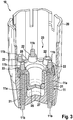
- One out Fig. 1 apparent contact assembly 1 comprises a total of four spring contact pins 11, which are arranged in a frusto-conical housing capsule 20 of insulating plastic and are used for electrical contacting of an attachment controller, not shown, for a brake device of a vehicle brake system with a pressure sensor of a sensor unit 30 for brake pressure measurement. Since the housing capsule 20 and the sensor unit 30 are shown broken on a peripheral side, one of the total four spring contact pins 11 in Fig. 1 only see three. From the underside of the sensor unit 30 is centrally from a pipe socket 31, which engages in the installed state under sealing in an associated bore of a hydraulic block, not shown, and thereby produces a fluidic connection of the pressure sensor to the hydraulic system of the associated brake system.
- the contact arrangement 1 is thus between sensor unit 30 and a cup-shaped control housing that the spring contact pins 11 under axial spring load with its lower end on the associated contact surface of the pressure sensor and with its upper end on the associated contact surface on the underside of the control housing rest and can ensure reliable signal transmission under all operating conditions, since the spring contact pins 11 end side with a defined contact pressure between the opposing contact surfaces of the sensor unit 30 on the one hand and the control electronics supported on the other.
- This contact corresponds to the illustrated contact arrangement 1 of the in the DE 19917941 A1 described construction, so that is omitted at this point to further explanations to the overall arrangement.
- the individual spring contact pins 11 are each bent in one piece as a winding spring made of good conductive spring wire, wherein the spring wire over the entire length of the spring winding has a constant circular cross-section.
- the spring winding of each of the identical spring contact pins 11 is also designed in principle as a helical compression spring and divided into three lengths, with only a central winding portion 11a is formed as an axially compressible helical compression spring, because the turns are wound in this longitudinal section at a corresponding distance extending each other.
- This middle winding section also has the largest and thereby constant winding diameter. Subsequently, the spring winding is wound on block at the middle winding portion 11 a, whereby no axial distance is between the individual spring coils.
- the spring coil tapers from the middle winding section 11a, starting with the interposition of a conical transition region to end regions of the spring contact pin 11 forming winding sections 11b.
- the end portions forming winding sections 11b each consist of a cylindrical bobbin, which is formed due to its superimposed turns axially compressive stiff and thus unyielding.
- the spring contact pins 11 can be compressed axially only in the winding section 11a forming the central region.
- the spring contact pins 11 are axially supported in each case between a conical annular end face of the predominantly receiving guide 21 and an associated contact 32 which is located on top of a contact plate 33 forming the upper end of the sensor unit 30.
- This recessed from the peripheral wall of the housing capsule 20 guide 21 has in a lower longitudinal section a clear inner diameter which is slightly larger than the winding diameter of the winding portion 11 a and merges in the upper length to form the conical annular end face into a through hole of smaller diameter, wherein the Bore diameter is slightly larger than the diameter of the winding portion 11b.
- the through hole terminates at the top of the housing capsule 20, wherein the winding portion 11 b protrudes with a partial length from the top of the housing capsule 20.
- the contact plate 33 and the guide 21 passes through the winding portion 11b of the spring contact pins 11 each have an associated guide 22, which is recessed from a collar 28 of a hood body designed as a clamping member 23.
- This clamping component 23 which is likewise produced from insulating plastic, is connected to the housing capsule 20 via a central cup-shaped press-in pin 26 and a plurality of positioning pins 24 of cylindrical basic shape projecting from an upper end face of the annular collar 28.
- the press-in pin 26 and the positioning pins 24 are molded onto the annular collar 28 and thus formed integrally therewith.
- the spring contact pins 11 can be combined in a simple manner with the housing capsule 20 and designed as a hood body clamping member 23 to a pre-assembly 10.
- the broken housing capsule 20 is in this case opposite to better visibility in a pre-assembly Fig. 1 Drawn rotated by 180 degrees. In this rotated position, the large diameter end of the guides 21 is above.
- the spring contact pins 11 can be easily inserted from above into the associated guides 21, after which their lower winding portion 11 b protrudes with a partial length from the lower side of the upper side of the housing capsule 20.
- the winding sections 11b penetrate their guide 22 until their conically wound transition region bears against the centering cone of the guide 22 under axial support.
- the clamping member 23 By subsequent depression of the clamping member 23 in the sense of a parallel shift down the spring contact pins 11 are increasingly compressed together. The compression takes place exclusively in the winding section 11a, since the winding sections 11b have a rigid behavior and consequently can not be compressed.
- the end of the central press-in pin 26 dips into an associated press-fit hole 27 recessed from the housing capsule 20, and the ends of the positioning pins 24 projecting downwardly from the lower end face of the annular collar 28 dip into their associated positioning holes 25 recessed from the housing capsule 20 one.
- the insertion of the Einpresszapfens 26 in its injection bore 27 and the insertion of the positioning pin 24 in the positioning holes are facilitated because the free ends of their cylindrical body are tapered conically similar to a circumferential chamfer.
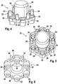
- hood body Clamping component 23 can be seen in a separate representation with its detailed designs.
- the main body of the clamping member 23 is a parallelepiped, approximately circular annular collar 28, on which a central Einpresszapfen 26 is formed. From one end face of the annular collar 28 are at right angles to the ring collar level, the positioning pins 24, while projecting from the opposite end face funnel-shaped sleeve body, which define the guide 22 together with an associated bore in the annular collar.
- the positioning pins 24 and the central cup-shaped press-in pin 26 extend in the same direction.
- Positioning pin 24 and guides 22 are arranged distributed uniformly over the end face of the annular collar 28 of the clamping member 23, wherein between two adjacent guides 22 each have a positioning pin 24 is arranged. As a result, a particularly favorable dimensioning of the clamping component 23 can take place.
- the clamping member 23 has six guides 22 and six positioning pin 24, although only four spring contact pins 11 are provided in the present application. This makes it possible that the housing capsule 20 can be used without structural changes for other contact arrangements with up to six spring contact pins 11.
Description
Die Erfindung betrifft eine Vormontagebaugruppe für eine Kontaktanordnung einer Sensorbaugruppe nach der Gattung des unabhängigen Patentanspruchs 1.The invention relates to a preassembly assembly for a contact arrangement of a sensor assembly according to the preamble of
In der Offenlegungsschrift
Aus der
Aus der
Aus der
Aus der
Aus der
Aus der
From the
From the
From the
From the
From the
From the
Die erfindungsgemäße Vormontagebaugruppe für eine Kontaktanordnung einer Sensorbaugruppe mit den Merkmalen des unabhängigen Patentanspruchs 1 hat demgegenüber den Vorteil, dass sich ein Tragbauteil und ein Klemmbauteil über Verbindungsmittel einfach miteinander verbinden lassen, so dass wenigstens ein Federkontaktstift über von ihm durchdrungene fluchtende Führungen im Tragbauteil und Klemmbauteil einfach positioniert und gehalten wird. Zur Bildung der erfindungsgemäßen Vormontagebaugruppe wird der mindestens eine Federkontaktstift in der Führung des Tragbauteils gehalten, wobei ein erster endseitiger Abschnitt des wenigstens einen Federkontaktstifts in der zugeordneten Führung des Tragbauteils axial abgestützt ist. Ein zweiter endseitiger Abschnitt des wenigstens einen Federkontaktstifts ist in der zugeordneten Führung des Klemmbauteils axial abgestützt, wobei das Klemmbauteil und das Tragbauteil in der fluchtenden Stellung der korrespondierenden Führungen über die Verbindungsmittel mit einander verbunden werden. Nach dem Verbinden des Klemmbauteils mit dem Tragbauteil ist der wenigstens eine Federkontaktstift automatisch auf die gewünschte Länge zusammengedrückt und wird unverlierbar in den fluchtenden Führungen des Klemmbauteils und des Tragbauteils in dieser Position gehalten. Dadurch entsteht in vorteilhafter Weise eine einfach zu handhabende Vormontagebaugruppe für eine Kontaktanordnung einer Sensorbaugruppe Hierbei werden die fluchtenden Führungen des Tragbauteils und des Klemmbauteils über Positioniermittel des korrespondierenden Tragbauteils bzw. Klemmbauteils problemlos in ihre Konstruktionslage gebracht, um miteinander verbunden zu werden. Als Verbindungsmittel zwischen dem Klemmbauteil und dem Tragbauteil ist mindestens ein Einpresszapfen vorgesehen, welcher im Einbauzustand in eine zugeordnete Einpressbohrung eingepresst ist. Hierbei können der Einpresszapfen und die zugeordnete Einpressbohrung konstruktiv so aufeinander abgestimmt werden, beispielsweise durch eine entsprechende Formvorgabe, dass im Einbauzustand eine positionsrichtige Verbindung zwischen dem Klemmbauteil und dem Tragbauteil erreichbar ist. Zudem sind als Positioniermittel zwischen dem Klemmbauteil und dem Tragbauteil mehrere Einpresszapfen und/oder Positionierungszapfen vorgesehen, die im Einbauzustand in zugeordneten Einpressbohrungen mit passendem Lochbild eingepresst sind. Um den Einpressvorgang in Anbetracht der relativ kleinen Abmessungen der einzelnen Komponenten zu erleichtern, kann als Verbindungsmittel zwischen dem Klemmbauteil und dem Tragbauteil in vorteilhafter Weise ein zentraler Einpresszapfen vorgesehen werden, welcher im Einbauzustand in eine zugeordnete Einpressbohrung eingepresst ist, wobei als Positionierungsmittel mehrere Positionierungszapfen vorgesehen werden können, welche während des Einpressvorgangs in zugeordnete Positionierungsbohrungen mit passendem Lochbild eingeführt werden. Die im Vergleich mit dem Einpresszapfen kleineren Positionierungszapfen dienen daher zur Lagepositionierung und dadurch auch als Verdrehschutz.
Durch die in den abhängigen Ansprüchen aufgeführten Maßnahmen und Weiterbildungen sind vorteilhafte Verbesserungen der im unabhängigen Patentanspruch 1 angegebenen Vormontagebaugruppe für eine Kontaktanordnung einer Sensorbaugruppe möglich.
Um günstige Einbauverhältnisse für mehrere Federkontaktstifte zu erzielen, können diese mit etwa gleichem Abstand voneinander entlang einer Kreisbahn angeordnet werden. Hierbei kann das die Federkontaktstifte aufnehmende Klemmbauteil bei geringem Material und Bauraumbedarf als Haubenkörper mit einem zentralen topfförmigen Einpresszapfen und einem angeformten radial auskragenden Ringbund ausgebildet sein, wobei die Führungen für den zugeordneten Endbereich des Federkontaktstiftes als trichterförmiger Hülsenkörper in den Ringbund integriert sind von einer ersten Stirnseite abstehen, und das als Haubenkörper ausgeführte Klemmbauteil im Einbauzustand über den zentralen Einpresszapfen und mehrere von einer zweiten Stirnseite des Ringbunds abstehende Positionierungszapfen mit dem korrespondierenden Tragbauteil verbunden ist. Hierbei erstrecken sich der zentrale Einpresszapfen und der mindestens eine Positionierungszapfen in die gleiche Richtung.
In Ausgestaltung der erfindungsgemäßen Vormontagebaugruppe ist der Federkontaktstift als Schraubendruckfeder ausgeführt und besteht zumindest überwiegend aus einer sich über seine gesamte konstruktive Länge erstreckenden Federwicklung, deren in den Endbereichen liegenden Wicklungsabschnitte durch Hemmung der Axialbeweglichkeit ihrer Federwindungen versteift sind. Dadurch ist in vorteilhafter Weise beim zumindest überwiegend als Wickelkörper ausgebildeten Federkontaktstift keine Gleitführung oder dgl. erforderlich, die des maßhaltigen Zusammenwirkens mehrerer Kontaktelemente bedarf. Vielmehr dient der mittlere Wicklungsabschnitt als kompressible Schraubendruckfeder, während die Wicklungsabschnitte in den druckversteiften Endbereichen zwar Federwindungen umfassen, die jedoch durch die axiale Einfederung hemmende Mittel inkompressibel und somit drucksteif gemacht sind. Solche axial hemmenden Mittel könnten z. B. hülsenförmige Umspritzungen aus Kunststoff sein, mit denen die Federwindungen in den Endbereichen jeweils bis nahe ihrem mit der Kontaktfläche zusammenwirkenden Ende ummantelt bzw. miteinander verbunden werden. Durch die bauliche Vereinfachung lässt sich bereits der einzelne Federkontaktstift sehr kostengünstig fertigen.The preassembly assembly according to the invention for a contact arrangement of a sensor assembly with the features of
The measures and refinements recited in the dependent claims advantageous improvements of the
In order to achieve favorable installation conditions for several spring contact pins, they can be arranged with approximately the same distance from each other along a circular path. Here, the spring contact pins receiving clamping member may be formed with low material and space requirements as hood body with a central cup-shaped press-in pin and a molded radially projecting collar, the guides are integrated for the associated end of the spring contact pin as a funnel-shaped sleeve body in the annular collar protrude from a first end face , And the clamping member designed as a hood body in the installed state via the central press-in pin and a plurality of projecting from a second end face of the annular collar positioning pin is connected to the corresponding support member. Here, the central press-in pin and the at least one positioning pin extend in the same direction.
In an embodiment of the preassembly assembly according to the invention, the spring contact pin is designed as a helical compression spring and consists at least predominantly of a over its entire constructive length extending spring winding whose lying in the end regions winding sections are stiffened by inhibiting the Axiolbeweglichkeit their spring turns. As a result, in an advantageous manner, at least predominantly designed as a winding body spring contact pin no sliding or the like. Necessary, which requires the dimensionally effective interaction of several contact elements. Rather, the middle winding section serves as a compressible helical compression spring, while the winding sections in the pressure-stiffened end regions although comprise spring coils, which are made incompressible and thus pressure-resistant by the axial deflection inhibiting means. Such axial inhibiting means could e.g. B. sleeve-shaped overmolding of plastic, with which the spring coils in the Enclosed end areas respectively close to their cooperating with the contact surface end or connected to each other. Due to the structural simplification, the single spring contact pin can already be manufactured very inexpensively.
Besonders vorteilhaft kann die Federwicklung des Federkontaktstiftes in beiden die Endbereiche bildenden Wicklungsabschnitten verjüngt sein. Die entsprechend verjüngten Enden des Federkontaktstiftes können hierbei mit entsprechend kleineren Kontaktgegenflächen zusammenwirken. Zudem kann das Drahtende der verjüngten Federwicklung selbst eine Art zentrale Kontaktspitze bilden, die mit entsprechend hoher Flächenpressung an der Kontaktgegenfläche aufliegen kann. Hinzu kommt noch, dass die auf die Federwicklung wirkenden Reaktionskräfte der Kontaktspitze nahezu zentrisch eingeleitet werden, da sie nahe der Mittellängsachse der Federwicklung liegen. Hierdurch wird der als Schraubendruckfeder genutzte mittlere Wicklungsabschnitt in geringerem Maße auf Biegung beansprucht und bedarf daher in diesem Mittelbereich nicht zwingend einer radialen Abstützung bzw. Führung, wenn die Endbereiche der Federwicklung bildenden Wicklungsabschnitte ihrerseits in passende Führungen eingreifen.Particularly advantageously, the spring winding of the spring contact pin can be tapered in both end portions forming winding sections. The correspondingly tapered ends of the spring contact pin can cooperate with correspondingly smaller contact opposing surfaces. In addition, the wire end of the tapered spring winding itself form a kind of central contact tip, which can rest with a correspondingly high surface pressure on the contact counter surface. In addition, the reaction forces of the contact tip acting on the spring winding are introduced almost centrally, since they are close to the central longitudinal axis of the spring winding. As a result, the medium winding section used as a helical compression spring is subjected to bending to a lesser extent and therefore does not necessarily require radial support or guidance in this central area when the end areas of the spring winding forming winding sections in turn engage in suitable guides.
Um auf einfache Weise eine axiale Abstützung und gleichzeitig eine Zentrierung der die Endbereiche bildenden Wicklungsabschnitte in der von ihnen durchdrungenen Führung herbeizuführen, kann der Übergangsbereich des Federkontaktstiftes von seinem mittleren Wicklungsabschnitt zum den verjüngten Endbereich bildenden Wicklungsabschnitt an den Endbereichen unter Anpassung an einen konischen Sitz in der zugeordneten Führung des Tragbauteils bzw. Klemmbauteils kegelförmig gewickelt sein. Durch eine spiegelsymmetrische Gestaltung des Federkontaktstiftes bezogen auf seine Mittelquerachse lässt sich dabei sicherstellen, dass der Federkontaktstift in beiden Endbereichen mit dem konischen Sitz zusammenwirken kann, wodurch die Montage des Federkontaktstiftes einfacher und dabei verwechslungssicher vorgenommen werden kann.In order to easily provide axial support and at the same time centering of the end portions forming winding sections in the guide penetrated by them, the transition region of the spring contact pin from its central winding portion to the tapered end portion forming winding portion at the end portions adapted to a conical seat in the associated guide of the support member or clamping member to be conically wound. By a mirror-symmetrical design of the spring contact pin relative to its central transverse axis can thereby ensure that the spring contact pin can cooperate in both end regions with the conical seat, whereby the assembly of the spring contact pin can be made easier and confusion.
Eine besonders einfache Bauweise des Federkontaktstiftes lässt sich realisieren, wenn die Federwindungen in den Endbereichen des erfindungsgemäßen Federkontaktstiftes zur axialen Versteifung dieser Endbereiche auf Block gewickelt sind. Hierdurch kann der Federkontaktstift ein einteilig aus Federdraht gewickelter Wickelkörper sein und somit in einem ggf. automatisierten Arbeitszyklus kostengünstig als Massenteil hergestellt werden. Zudem kann die radiale Abstützung der kegelförmigen Übergangsbereiche in den konischen Führungsmitteln dadurch verbessert werden, dass die Federwindungen in den kegelförmigen Übergangsbereichen des Federkontaktstiftes zumindest überwiegend oder vollständig ebenfalls auf Block gewickelt sind. Der Kostenvorteil wirkt sich bei einer Kontaktierung für eine Sensorbaugruppe oder dergleichen besonders vorteilhaft aus, wenn diese mehrere Federkontaktstifte umfasst, die alle baugleich gestaltet sind.A particularly simple design of the spring contact pin can be realized if the spring coils are wound in the end regions of the spring contact pin according to the invention for the axial stiffening of these end portions on block. In this way, the spring contact pin can be a wound coil body wound in one piece from spring wire and thus be manufactured inexpensively as a mass part in an optionally automated work cycle. In addition, the radial support of the conical transition regions in the conical guide means can be improved in that the spring coils in the Conical transition regions of the spring contact pin are at least predominantly or completely wound on block. The cost advantage has a particularly advantageous in a contact for a sensor assembly or the like, if this includes a plurality of spring contact pins, which are all designed identical.
Eine vorteilhafte Ausführungsform der Erfindung ist nachfolgend anhand von Zeichnungen nähern erläutert. In den Zeichnungen bezeichnen gleiche Bezugszeichen zugeordnete Komponenten bzw. Elemente, die gleiche bzw. analoge Funktionen ausführen.An advantageous embodiment of the invention is explained below with reference to drawings. In the drawings, like reference numerals designate associated components or elements that perform the same or analog functions.
-
Fig. 1 zeigt eine Kontaktanordnung an einer aufgeschnittenen Baugruppe eines Drucksensors für ein Fluidaggregat in perspektivischer Schrägansicht.Fig. 1 shows a contact arrangement on a cut assembly of a pressure sensor for a fluid assembly in a perspective oblique view. -
Fig. 2 eine perspektivische Schrägansicht auf eine Gehäusekapsel der Baugruppe bei der Vormontage der Federkontaktstifte unter Verwendung eines Klemmbauteils.Fig. 2 a perspective oblique view of a housing capsule of the assembly in the pre-assembly of the spring contact pins using a clamping member. -
Fig. 3 die Schrägansicht nachFig. 2 nach Abschluss der Vormontage der Federkontaktstifte.Fig. 3 the oblique viewFig. 2 after completion of the pre-assembly of the spring contact pins. -
Fig. 4 das separate Klemmbauteil von seiner Unterseite in perspektivischer Schrägansicht.Fig. 4 the separate clamping member from its underside in perspective oblique view. -
Fig. 5 das Klemmbauteil gemäßFig. 4 in einer perspektivischen Draufsicht.Fig. 5 the clamping component according toFig. 4 in a perspective plan view. -
Fig. 6 das separate Klemmbauteil von seiner Oberseite in perspektivischer Schrägansicht.Fig. 6 the separate clamping member from its top in perspective oblique view.
Eine aus
Die einzelnen Federkontaktstifte 11 sind jeweils einteilig als Wickelfeder aus gut leitendem Federdraht gebogen, wobei der Federdraht über die gesamte Länge der Federwicklung einen konstanten Rundquerschnitt aufweist. Die Federwicklung jedes der baugleichen Federkontaktstifte 11 ist ferner prinzipiell als Schraubendruckfeder ausgelegt und in drei Längenabschnitte gegliedert, wobei lediglich ein mittlerer Wicklungsabschnitt 11a als axial zusammendrückbare Schraubendruckfeder ausgebildet ist, weil die Windungen in diesem Längenabschnitt in entsprechendem Abstand zueinander verlaufend gewickelt sind. Dieser mittlere Wicklungsabschnitt weist auch den größten und dabei konstanten Wicklungsdurchmesser auf. An den mittleren Wicklungsabschnitt 11a anschließend ist die Federwicklung jeweils auf Block gewickelt, wodurch sich zwischen den einzelnen Federwindungen kein axialer Abstand mehr befindet. Außerdem verjüngt sich die Federwicklung vom mittleren Wicklungsabschnitt 11a ausgehend unter Zwischenschaltung eines kegelförmigen Übergangsbereichs zu Endbereiche des Federkontaktstiftes 11 bildenden Wicklungsabschnitten 11b. Die Endbereiche bildenden Wicklungsabschnitte 11b bestehen dabei jeweils aus einem zylindrischen Wickelkörper, der aufgrund seiner aufeinanderliegenden Windungen axial drucksteif und somit unnachgiebig ausgebildet ist.The individual spring contact pins 11 are each bent in one piece as a winding spring made of good conductive spring wire, wherein the spring wire over the entire length of the spring winding has a constant circular cross-section. The spring winding of each of the identical spring contact pins 11 is also designed in principle as a helical compression spring and divided into three lengths, with only a central winding
Aufgrund dieser unnachgiebigen Gestaltung der Wicklungsabschnitte 11b sowie der kegelförmig auf Block gewickelten Übergangsbereiche lassen sich die Federkontaktstifte 11 lediglich im den Mittelbereich bildenden Wicklungsabschnitt 11a axial zusammendrücken.Due to this unyielding configuration of the winding
Im Vormontagezustand mit entsprechend verkürzter Federwicklung sind die Federkontaktstifte 11 axial jeweils zwischen einer konischen Ringstirnfläche der sie überwiegend aufnehmenden Führung 21 und einem zugeordneten Kontakt 32 abgestützt, der sich auf der Oberseite einer den oberen Abschluss der Sensoreinheit 30 bildenden Kontaktplatte 33 befindet. Diese aus der Umfangswand der Gehäusekapsel 20 ausgesparte Führung 21 weist in einem unteren Längenabschnitt einen lichten Innendurchmesser auf, der geringfügig größer ist als der Wicklungsdurchmesser des Wicklungsabschnittes 11a und geht im oberen Längenabschnitt unter Ausbildung der konischen Ringstirnfläche in eine Durchgangsbohrung mit geringerem Durchmesser über, wobei der Bohrungsdurchmesser geringfügig größer ist als der Durchmesser des Wicklungsabschnittes 11b. Die Durchgangsbohrung endet an der Oberseite der Gehäusekapsel 20, wobei der Wicklungsabschnitt 11b mit einer Teillänge aus der Oberseite der Gehäusekapsel 20 heraussteht. Zwischen der Kontaktplatte 33 und der Führung 21 durchsetzt der Wicklungsabschnitt 11b der Federkontaktstifte 11 jeweils eine zugeordnete Führung 22, die aus einem Ringbund 28 eines als Haubenkörpers ausgeführten Klemmbauteils 23 ausgespart ist. Dieses ebenfalls aus isolierendem Kunststoff hergestellte Klemmbauteil 23 ist über einen zentralen topfförmigen Einpresszapfen 26 und mehrere von einer oberen Stirnseite des Ringbunds 28 abstehende Positionierungszapfen 24 zylindrischer Grundform mit der Gehäusekapsel 20 verbunden. Vorzugsweise sind der Einpresszapfen 26 und die Positionierungszapfen 24 an den Ringbund 28 angespritzt und somit einteilig mit diesem ausgebildet.In the preassembled state with a correspondingly shortened spring winding, the spring contact pins 11 are axially supported in each case between a conical annular end face of the predominantly receiving
Wie in Verbindung mit den
Nachdem das als Haubenkörper ausgeführte Klemmbauteil 23 seine in
In den
Claims (6)
- Preassembled assembly for a contact arrangement of a sensor assembly, having a supporting component (20), a clamping component (23) and at least one spring contact pin (11), wherein conductively interconnected end regions of the at least one spring contact pin (11) are formed so as to be axially rigid under pressure and are held, in an axially spring-loaded manner, between support faces that are arranged in a manner spaced apart from one another, characterized in that the supporting component (20) and the clamping component (23) are connected together via connecting means, wherein the at least one spring contact pin (11) is positioned and held in the supporting component (20) and in the clamping component (23) via aligned guides (21, 22) through which said spring contact pin (11) passes, wherein a first end-side portion (11b) of the at least one spring contact pin (11) is axially supported in the associated guide (21) of the supporting component (20), and wherein a second end-side portion (11b) of the at least one spring contact pin (11) is axially supported in the associated guide (22) of the clamping component (23), wherein the supporting component (20) and the clamping component (23) are connected together via positioning means in the aligned position of the guides (21) of the supporting component (20) with respect to the guides (22) in the clamping component (23), wherein at least one push-fit peg (24, 26) is provided as connecting means between the clamping component (23) and the supporting component (20), said push-fit peg (24, 26), in the installed state, having been pushed into an associated push-fit hole (25, 27), and wherein a plurality of pegs (24) are provided as positioning means between the clamping component (23) and the supporting component (20), said pegs (24), in the installed state, having been pushed into associated holes (25) with a matching hole pattern.
- Preassembled assembly according to Claim 1, characterized in that a central push-fit peg (26) is provided as connecting means between the clamping component (23) and the supporting component (20), and in that a plurality of positioning pegs (24) are provided as positioning means, wherein, in the installed state, the central push-fit peg (26) has been pushed into an associated push-fit hole (27), and the positioning pegs (24) have been introduced into associated positioning holes (25) with a matching hole pattern.
- Preassembled assembly according to Claim 1 or 2, characterized in that the clamping component (23) is embodied as a hood body with a central cup-shaped push-fit peg (26) and an integrally formed radially projecting annular collar (28), wherein at least one positioning peg (24) protrudes at right angles from one end side of the annular collar (28), and on the opposite end side of the annular collar (28) at least one guide (22) embodied as a funnel-shaped sleeve body protrudes, wherein the central push-fit peg (26) and the at least one positioning peg (24) extend in the same direction.
- Preassembled assembly according to one of Claims 1 to 3, characterized in that the spring contact pin (11) is embodied as a helical compression spring and consists at least predominantly of a spring winding extending along its entire structural length, the winding portions (11b) of said spring winding that are located in the end regions being stiffened by the axial movability of their spring coils being inhibited.
- Preassembled assembly according to Claim 4, characterized in that the two end regions of the spring contact pin (11) are each formed by a narrowed winding portion (11b), wherein the winding portions (11b) arranged on opposite sides with respect to the central transverse axis of the spring contact pin (11) are designed in a mirror-symmetrical manner, wherein the transition regions of the spring contact pin (11) from its central winding portion (11a) to the winding portions (11b) forming narrowed end regions are each wound in a conical manner, being adapted to a conical seat in the associated guide (21) of the supporting component (20) and/or to a conical seat in the associated guide (22) of the clamping component (23).
- Preassembled assembly according to Claim 4 or 5, characterized in that the winding portions (11b), forming end regions, of the spring contact pin (11) are stiffened by spring coils wound to form a solid block, wherein the spring coils are likewise wound to form a solid block in the conical transition regions of the spring contact pin (11).
Applications Claiming Priority (2)
| Application Number | Priority Date | Filing Date | Title |
|---|---|---|---|
| DE102008040180A DE102008040180A1 (en) | 2008-07-04 | 2008-07-04 | Pre-assembly for a contact assembly of a sensor assembly |
| PCT/EP2009/058349 WO2010000814A1 (en) | 2008-07-04 | 2009-07-02 | Pre-installation assembly for a contact arrangement of a sensor assembly |
Publications (2)
| Publication Number | Publication Date |
|---|---|
| EP2297561A1 EP2297561A1 (en) | 2011-03-23 |
| EP2297561B1 true EP2297561B1 (en) | 2018-09-12 |
Family
ID=41100774
Family Applications (1)
| Application Number | Title | Priority Date | Filing Date |
|---|---|---|---|
| EP09772514.7A Active EP2297561B1 (en) | 2008-07-04 | 2009-07-02 | Pre-installation assembly for a contact arrangement of a sensor assembly |
Country Status (6)
| Country | Link |
|---|---|
| US (1) | US8822821B2 (en) |
| EP (1) | EP2297561B1 (en) |
| JP (1) | JP5322130B2 (en) |
| CN (1) | CN102084234B (en) |
| DE (1) | DE102008040180A1 (en) |
| WO (1) | WO2010000814A1 (en) |
Families Citing this family (18)
| Publication number | Priority date | Publication date | Assignee | Title |
|---|---|---|---|---|
| DE102010063709A1 (en) * | 2010-12-21 | 2012-06-21 | Robert Bosch Gmbh | Device for electrical contacting of electronic units |
| KR101897293B1 (en) * | 2012-09-28 | 2018-09-11 | 타이코에이엠피 주식회사 | Pressure sensor |
| CN103531936A (en) * | 2013-10-30 | 2014-01-22 | 中航光电科技股份有限公司 | Spring coiled type combination jack |
| DE102013114140A1 (en) * | 2013-12-16 | 2015-06-18 | Endress + Hauser Wetzer Gmbh + Co. Kg | Sensor housing and sensor arrangement with a sensor housing |
| US9568388B2 (en) | 2014-08-05 | 2017-02-14 | Sensata Technologies, Inc. | Small form factor pressure sensor |
| WO2016198335A1 (en) * | 2015-06-09 | 2016-12-15 | Moog Gmbh | Pressure sensor module with electrical contacts |
| CN107290099B (en) | 2016-04-11 | 2021-06-08 | 森萨塔科技公司 | Pressure sensor, plug for a pressure sensor and method for producing a plug |
| EP3236226B1 (en) | 2016-04-20 | 2019-07-24 | Sensata Technologies, Inc. | Method of manufacturing a pressure sensor |
| CN105922982B (en) * | 2016-06-13 | 2018-07-13 | 眉山中车制动科技股份有限公司 | A kind of truck air brake single-site data acquisition device |
| CN105905097B (en) * | 2016-06-13 | 2018-06-29 | 眉山中车制动科技股份有限公司 | A kind of truck air brake multi-point data acquisition device |
| DE102016214940A1 (en) * | 2016-08-11 | 2018-02-15 | Robert Bosch Gmbh | Pressure measuring cell and method for applying a measuring structure |
| US10545064B2 (en) | 2017-05-04 | 2020-01-28 | Sensata Technologies, Inc. | Integrated pressure and temperature sensor |
| DE102017209650A1 (en) * | 2017-06-08 | 2018-12-13 | Robert Bosch Gmbh | Micromechanical pressure sensor arrangement and method for producing a micromechanical pressure sensor arrangement |
| US10323998B2 (en) | 2017-06-30 | 2019-06-18 | Sensata Technologies, Inc. | Fluid pressure sensor |
| US10724907B2 (en) | 2017-07-12 | 2020-07-28 | Sensata Technologies, Inc. | Pressure sensor element with glass barrier material configured for increased capacitive response |
| US10557770B2 (en) | 2017-09-14 | 2020-02-11 | Sensata Technologies, Inc. | Pressure sensor with improved strain gauge |
| CN111356311B (en) * | 2018-12-20 | 2021-06-18 | 英觉消防安全科技股份有限公司 | Detector easy to disassemble and assemble quickly |
| CN114607202B (en) * | 2022-04-27 | 2024-02-23 | 江西仙廷精藏设备有限公司 | Beam column mortise and tenon type crematory urn storage device |
Citations (2)
| Publication number | Priority date | Publication date | Assignee | Title |
|---|---|---|---|---|
| JPH07161416A (en) * | 1993-12-02 | 1995-06-23 | Excel Denshi:Kk | Connector for substrate |
| EP1113275A1 (en) * | 1998-07-10 | 2001-07-04 | Nhk Spring Co.Ltd. | Conductive contact |
Family Cites Families (14)
| Publication number | Priority date | Publication date | Assignee | Title |
|---|---|---|---|---|
| US4029375A (en) * | 1976-06-14 | 1977-06-14 | Electronic Engineering Company Of California | Miniature electrical connector |
| EP0113275B1 (en) | 1982-12-17 | 1989-03-01 | Victor Company Of Japan, Limited | Spectrum display device for audio signals |
| US4522096A (en) * | 1983-06-16 | 1985-06-11 | R. J. Reynolds Tobacco Company | Dicing apparatus for sheet material |
| US4536820A (en) * | 1984-03-29 | 1985-08-20 | General Signal Corporation | Electrical feedthrough means for pressure transducer |
| EP0616394A1 (en) * | 1993-03-16 | 1994-09-21 | Hewlett-Packard Company | Method and system for producing electrically interconnected circuits |
| JP3414593B2 (en) * | 1996-06-28 | 2003-06-09 | 日本発条株式会社 | Conductive contact |
| DE19917941A1 (en) | 1999-04-21 | 2000-10-26 | Bosch Gmbh Robert | Electro-hydraulic braking system for motor vehicles has control electronics and pressure sensor arranged in a single unit that can be automatically mounted during vehicle assembly |
| US6341962B1 (en) * | 1999-10-29 | 2002-01-29 | Aries Electronics, Inc. | Solderless grid array connector |
| JP4990463B2 (en) * | 2000-05-11 | 2012-08-01 | コンティネンタル・テーベス・アクチエンゲゼルシヤフト・ウント・コンパニー・オッフェネ・ハンデルスゲゼルシヤフト | Brake device with integrated pressure sensor module |
| DE50102005D1 (en) * | 2001-11-28 | 2004-05-19 | Festo Ag & Co | Connection piece, fluid line and fluid technology device |
| DE10244760A1 (en) | 2002-02-26 | 2003-10-09 | Continental Teves Ag & Co Ohg | Pressure sensor structural component for a motor vehicle brake unit has electric connection for measuring element, contact carrier and threading funnel for inserting a contact pin |
| US6742395B1 (en) * | 2002-12-20 | 2004-06-01 | Texas Instruments Incorporated | Hermetic pressure transducer |
| US6846184B2 (en) * | 2003-01-24 | 2005-01-25 | High Connection Density Inc. | Low inductance electrical contacts and LGA connector system |
| DE102007038534A1 (en) * | 2007-08-16 | 2009-02-19 | Robert Bosch Gmbh | Contact component for electrical contacting of two components, particularly fluid assembly, has multiple contact spring elements, which are held from carrier element, and individual contact spring element with contact area |
-
2008
- 2008-07-04 DE DE102008040180A patent/DE102008040180A1/en not_active Withdrawn
-
2009
- 2009-07-02 CN CN200980125983.9A patent/CN102084234B/en not_active Expired - Fee Related
- 2009-07-02 EP EP09772514.7A patent/EP2297561B1/en active Active
- 2009-07-02 US US13/002,608 patent/US8822821B2/en active Active
- 2009-07-02 JP JP2011515461A patent/JP5322130B2/en not_active Expired - Fee Related
- 2009-07-02 WO PCT/EP2009/058349 patent/WO2010000814A1/en active Application Filing
Patent Citations (2)
| Publication number | Priority date | Publication date | Assignee | Title |
|---|---|---|---|---|
| JPH07161416A (en) * | 1993-12-02 | 1995-06-23 | Excel Denshi:Kk | Connector for substrate |
| EP1113275A1 (en) * | 1998-07-10 | 2001-07-04 | Nhk Spring Co.Ltd. | Conductive contact |
Also Published As
| Publication number | Publication date |
|---|---|
| JP2011526682A (en) | 2011-10-13 |
| CN102084234A (en) | 2011-06-01 |
| CN102084234B (en) | 2015-04-29 |
| JP5322130B2 (en) | 2013-10-23 |
| DE102008040180A1 (en) | 2010-01-14 |
| WO2010000814A1 (en) | 2010-01-07 |
| US8822821B2 (en) | 2014-09-02 |
| US20110108322A1 (en) | 2011-05-12 |
| EP2297561A1 (en) | 2011-03-23 |
Similar Documents
| Publication | Publication Date | Title |
|---|---|---|
| EP2297561B1 (en) | Pre-installation assembly for a contact arrangement of a sensor assembly | |
| DE102007005737A1 (en) | Headrest system for a vehicle seat | |
| DE2550245A1 (en) | CONNECTING CLAMP FOR A DEVICE OR ELEMENT FOR ELECTRICAL CONNECTION | |
| EP3262716A1 (en) | Contacting device for the transmission of electrical energy to a circuit board and method for the assembly of such a contacting device | |
| DE3908617C2 (en) | ||
| WO2015044067A2 (en) | Device for feeding lines through a separating element in a sealed manner | |
| EP2200125B1 (en) | Shielded connector | |
| EP2933804B1 (en) | Induction component | |
| DE3625384C2 (en) | ||
| DE2323612A1 (en) | ELECTRICAL CONNECTOR | |
| EP1245061B1 (en) | Electrical connector | |
| DE102019210252B4 (en) | Method for manufacturing an electrical assembly and injection molding tool | |
| DE10304248A1 (en) | Terminal clamp device for connecting a ring cable lug and associated electrical device | |
| DE10237666B4 (en) | connector element | |
| EP3766130B1 (en) | Contact element having a contact body and a spring element arranged thereon | |
| EP0512088B1 (en) | Switch lever of a steering column switch for motor vehicles | |
| DE102008040173A1 (en) | Contact arrangement for sensor assembly of brake device of vehicle braking system, has spring contact pin comprising spring coils extending over entire constructional length and reinforced in coil sections by inhibiting axial mobility | |
| WO2011113863A1 (en) | Arrangement comprising an electric and/or electronic module and a circuit carrier | |
| EP1563519A1 (en) | Electrical contacting of thin enameled wires of secondary windings of ignition coils | |
| DE3805103A1 (en) | DEVICE FOR AUTOMATICALLY DISTRIBUTING SLEEVES FOR ELECTRIC CABLE LADDERS | |
| WO2019105655A1 (en) | Contacting device for an electrically actuatable valve which is arranged within a vibration damper | |
| WO2018153409A1 (en) | Connection element | |
| EP3503308B1 (en) | Insulation body and connector | |
| DE3721045C1 (en) | Device for mounting plug pins in the insulating body of a plug connector | |
| DE4236794C2 (en) | Electrical connector |
Legal Events
| Date | Code | Title | Description |
|---|---|---|---|
| PUAI | Public reference made under article 153(3) epc to a published international application that has entered the european phase |
Free format text: ORIGINAL CODE: 0009012 |
|
| 17P | Request for examination filed |
Effective date: 20110204 |
|
| AK | Designated contracting states |
Kind code of ref document: A1 Designated state(s): AT BE BG CH CY CZ DE DK EE ES FI FR GB GR HR HU IE IS IT LI LT LU LV MC MK MT NL NO PL PT RO SE SI SK SM TR |
|
| AX | Request for extension of the european patent |
Extension state: AL BA RS |
|
| DAX | Request for extension of the european patent (deleted) | ||
| TPAC | Observations filed by third parties |
Free format text: ORIGINAL CODE: EPIDOSNTIPA |
|
| 17Q | First examination report despatched |
Effective date: 20151125 |
|
| REG | Reference to a national code |
Ref country code: DE Ref legal event code: R079 Ref document number: 502009015277 Country of ref document: DE Free format text: PREVIOUS MAIN CLASS: G01L0009140000 Ipc: B60T0008360000 |
|
| RIC1 | Information provided on ipc code assigned before grant |
Ipc: H01R 13/24 20060101ALI20180213BHEP Ipc: B60T 8/36 20060101AFI20180213BHEP Ipc: G01L 19/00 20060101ALI20180213BHEP Ipc: G01L 19/14 20060101ALI20180213BHEP |
|
| GRAP | Despatch of communication of intention to grant a patent |
Free format text: ORIGINAL CODE: EPIDOSNIGR1 |
|
| STAA | Information on the status of an ep patent application or granted ep patent |
Free format text: STATUS: GRANT OF PATENT IS INTENDED |
|
| INTG | Intention to grant announced |
Effective date: 20180430 |
|
| GRAS | Grant fee paid |
Free format text: ORIGINAL CODE: EPIDOSNIGR3 |
|
| GRAA | (expected) grant |
Free format text: ORIGINAL CODE: 0009210 |
|
| STAA | Information on the status of an ep patent application or granted ep patent |
Free format text: STATUS: THE PATENT HAS BEEN GRANTED |
|
| AK | Designated contracting states |
Kind code of ref document: B1 Designated state(s): AT BE BG CH CY CZ DE DK EE ES FI FR GB GR HR HU IE IS IT LI LT LU LV MC MK MT NL NO PL PT RO SE SI SK SM TR |
|
| REG | Reference to a national code |
Ref country code: GB Ref legal event code: FG4D Free format text: NOT ENGLISH |
|
| REG | Reference to a national code |
Ref country code: CH Ref legal event code: EP |
|
| REG | Reference to a national code |
Ref country code: IE Ref legal event code: FG4D Free format text: LANGUAGE OF EP DOCUMENT: GERMAN |
|
| REG | Reference to a national code |
Ref country code: DE Ref legal event code: R096 Ref document number: 502009015277 Country of ref document: DE |
|
| REG | Reference to a national code |
Ref country code: AT Ref legal event code: REF Ref document number: 1040176 Country of ref document: AT Kind code of ref document: T Effective date: 20181015 |
|
| REG | Reference to a national code |
Ref country code: NL Ref legal event code: MP Effective date: 20180912 |
|
| REG | Reference to a national code |
Ref country code: LT Ref legal event code: MG4D |
|
| PG25 | Lapsed in a contracting state [announced via postgrant information from national office to epo] |
Ref country code: LT Free format text: LAPSE BECAUSE OF FAILURE TO SUBMIT A TRANSLATION OF THE DESCRIPTION OR TO PAY THE FEE WITHIN THE PRESCRIBED TIME-LIMIT Effective date: 20180912 Ref country code: BG Free format text: LAPSE BECAUSE OF FAILURE TO SUBMIT A TRANSLATION OF THE DESCRIPTION OR TO PAY THE FEE WITHIN THE PRESCRIBED TIME-LIMIT Effective date: 20181212 Ref country code: SE Free format text: LAPSE BECAUSE OF FAILURE TO SUBMIT A TRANSLATION OF THE DESCRIPTION OR TO PAY THE FEE WITHIN THE PRESCRIBED TIME-LIMIT Effective date: 20180912 Ref country code: GR Free format text: LAPSE BECAUSE OF FAILURE TO SUBMIT A TRANSLATION OF THE DESCRIPTION OR TO PAY THE FEE WITHIN THE PRESCRIBED TIME-LIMIT Effective date: 20181213 Ref country code: FI Free format text: LAPSE BECAUSE OF FAILURE TO SUBMIT A TRANSLATION OF THE DESCRIPTION OR TO PAY THE FEE WITHIN THE PRESCRIBED TIME-LIMIT Effective date: 20180912 Ref country code: NO Free format text: LAPSE BECAUSE OF FAILURE TO SUBMIT A TRANSLATION OF THE DESCRIPTION OR TO PAY THE FEE WITHIN THE PRESCRIBED TIME-LIMIT Effective date: 20181212 |
|
| PG25 | Lapsed in a contracting state [announced via postgrant information from national office to epo] |
Ref country code: ES Free format text: LAPSE BECAUSE OF FAILURE TO SUBMIT A TRANSLATION OF THE DESCRIPTION OR TO PAY THE FEE WITHIN THE PRESCRIBED TIME-LIMIT Effective date: 20180912 Ref country code: HR Free format text: LAPSE BECAUSE OF FAILURE TO SUBMIT A TRANSLATION OF THE DESCRIPTION OR TO PAY THE FEE WITHIN THE PRESCRIBED TIME-LIMIT Effective date: 20180912 Ref country code: LV Free format text: LAPSE BECAUSE OF FAILURE TO SUBMIT A TRANSLATION OF THE DESCRIPTION OR TO PAY THE FEE WITHIN THE PRESCRIBED TIME-LIMIT Effective date: 20180912 |
|
| PG25 | Lapsed in a contracting state [announced via postgrant information from national office to epo] |
Ref country code: NL Free format text: LAPSE BECAUSE OF FAILURE TO SUBMIT A TRANSLATION OF THE DESCRIPTION OR TO PAY THE FEE WITHIN THE PRESCRIBED TIME-LIMIT Effective date: 20180912 Ref country code: EE Free format text: LAPSE BECAUSE OF FAILURE TO SUBMIT A TRANSLATION OF THE DESCRIPTION OR TO PAY THE FEE WITHIN THE PRESCRIBED TIME-LIMIT Effective date: 20180912 Ref country code: RO Free format text: LAPSE BECAUSE OF FAILURE TO SUBMIT A TRANSLATION OF THE DESCRIPTION OR TO PAY THE FEE WITHIN THE PRESCRIBED TIME-LIMIT Effective date: 20180912 Ref country code: IT Free format text: LAPSE BECAUSE OF FAILURE TO SUBMIT A TRANSLATION OF THE DESCRIPTION OR TO PAY THE FEE WITHIN THE PRESCRIBED TIME-LIMIT Effective date: 20180912 Ref country code: CZ Free format text: LAPSE BECAUSE OF FAILURE TO SUBMIT A TRANSLATION OF THE DESCRIPTION OR TO PAY THE FEE WITHIN THE PRESCRIBED TIME-LIMIT Effective date: 20180912 Ref country code: IS Free format text: LAPSE BECAUSE OF FAILURE TO SUBMIT A TRANSLATION OF THE DESCRIPTION OR TO PAY THE FEE WITHIN THE PRESCRIBED TIME-LIMIT Effective date: 20190112 Ref country code: PL Free format text: LAPSE BECAUSE OF FAILURE TO SUBMIT A TRANSLATION OF THE DESCRIPTION OR TO PAY THE FEE WITHIN THE PRESCRIBED TIME-LIMIT Effective date: 20180912 |
|
| PG25 | Lapsed in a contracting state [announced via postgrant information from national office to epo] |
Ref country code: SM Free format text: LAPSE BECAUSE OF FAILURE TO SUBMIT A TRANSLATION OF THE DESCRIPTION OR TO PAY THE FEE WITHIN THE PRESCRIBED TIME-LIMIT Effective date: 20180912 Ref country code: SK Free format text: LAPSE BECAUSE OF FAILURE TO SUBMIT A TRANSLATION OF THE DESCRIPTION OR TO PAY THE FEE WITHIN THE PRESCRIBED TIME-LIMIT Effective date: 20180912 Ref country code: PT Free format text: LAPSE BECAUSE OF FAILURE TO SUBMIT A TRANSLATION OF THE DESCRIPTION OR TO PAY THE FEE WITHIN THE PRESCRIBED TIME-LIMIT Effective date: 20190112 |
|
| REG | Reference to a national code |
Ref country code: DE Ref legal event code: R097 Ref document number: 502009015277 Country of ref document: DE |
|
| PLBE | No opposition filed within time limit |
Free format text: ORIGINAL CODE: 0009261 |
|
| STAA | Information on the status of an ep patent application or granted ep patent |
Free format text: STATUS: NO OPPOSITION FILED WITHIN TIME LIMIT |
|
| PG25 | Lapsed in a contracting state [announced via postgrant information from national office to epo] |
Ref country code: DK Free format text: LAPSE BECAUSE OF FAILURE TO SUBMIT A TRANSLATION OF THE DESCRIPTION OR TO PAY THE FEE WITHIN THE PRESCRIBED TIME-LIMIT Effective date: 20180912 |
|
| 26N | No opposition filed |
Effective date: 20190613 |
|
| PG25 | Lapsed in a contracting state [announced via postgrant information from national office to epo] |
Ref country code: SI Free format text: LAPSE BECAUSE OF FAILURE TO SUBMIT A TRANSLATION OF THE DESCRIPTION OR TO PAY THE FEE WITHIN THE PRESCRIBED TIME-LIMIT Effective date: 20180912 |
|
| PG25 | Lapsed in a contracting state [announced via postgrant information from national office to epo] |
Ref country code: MC Free format text: LAPSE BECAUSE OF FAILURE TO SUBMIT A TRANSLATION OF THE DESCRIPTION OR TO PAY THE FEE WITHIN THE PRESCRIBED TIME-LIMIT Effective date: 20180912 |
|
| REG | Reference to a national code |
Ref country code: CH Ref legal event code: PL |
|
| PG25 | Lapsed in a contracting state [announced via postgrant information from national office to epo] |
Ref country code: TR Free format text: LAPSE BECAUSE OF FAILURE TO SUBMIT A TRANSLATION OF THE DESCRIPTION OR TO PAY THE FEE WITHIN THE PRESCRIBED TIME-LIMIT Effective date: 20180912 |
|
| REG | Reference to a national code |
Ref country code: BE Ref legal event code: MM Effective date: 20190731 |
|
| PG25 | Lapsed in a contracting state [announced via postgrant information from national office to epo] |
Ref country code: LU Free format text: LAPSE BECAUSE OF NON-PAYMENT OF DUE FEES Effective date: 20190702 Ref country code: LI Free format text: LAPSE BECAUSE OF NON-PAYMENT OF DUE FEES Effective date: 20190731 Ref country code: CH Free format text: LAPSE BECAUSE OF NON-PAYMENT OF DUE FEES Effective date: 20190731 Ref country code: BE Free format text: LAPSE BECAUSE OF NON-PAYMENT OF DUE FEES Effective date: 20190731 |
|
| PG25 | Lapsed in a contracting state [announced via postgrant information from national office to epo] |
Ref country code: IE Free format text: LAPSE BECAUSE OF NON-PAYMENT OF DUE FEES Effective date: 20190702 |
|
| REG | Reference to a national code |
Ref country code: AT Ref legal event code: MM01 Ref document number: 1040176 Country of ref document: AT Kind code of ref document: T Effective date: 20190702 |
|
| PG25 | Lapsed in a contracting state [announced via postgrant information from national office to epo] |
Ref country code: AT Free format text: LAPSE BECAUSE OF NON-PAYMENT OF DUE FEES Effective date: 20190702 |
|
| PG25 | Lapsed in a contracting state [announced via postgrant information from national office to epo] |
Ref country code: CY Free format text: LAPSE BECAUSE OF FAILURE TO SUBMIT A TRANSLATION OF THE DESCRIPTION OR TO PAY THE FEE WITHIN THE PRESCRIBED TIME-LIMIT Effective date: 20180912 |
|
| PG25 | Lapsed in a contracting state [announced via postgrant information from national office to epo] |
Ref country code: MT Free format text: LAPSE BECAUSE OF FAILURE TO SUBMIT A TRANSLATION OF THE DESCRIPTION OR TO PAY THE FEE WITHIN THE PRESCRIBED TIME-LIMIT Effective date: 20180912 Ref country code: HU Free format text: LAPSE BECAUSE OF FAILURE TO SUBMIT A TRANSLATION OF THE DESCRIPTION OR TO PAY THE FEE WITHIN THE PRESCRIBED TIME-LIMIT; INVALID AB INITIO Effective date: 20090702 |
|
| PG25 | Lapsed in a contracting state [announced via postgrant information from national office to epo] |
Ref country code: MK Free format text: LAPSE BECAUSE OF FAILURE TO SUBMIT A TRANSLATION OF THE DESCRIPTION OR TO PAY THE FEE WITHIN THE PRESCRIBED TIME-LIMIT Effective date: 20180912 |
|
| PGFP | Annual fee paid to national office [announced via postgrant information from national office to epo] |
Ref country code: GB Payment date: 20220725 Year of fee payment: 14 |
|
| PGFP | Annual fee paid to national office [announced via postgrant information from national office to epo] |
Ref country code: FR Payment date: 20220725 Year of fee payment: 14 |
|
| REG | Reference to a national code |
Ref country code: DE Ref legal event code: R084 Ref document number: 502009015277 Country of ref document: DE |
|
| PGFP | Annual fee paid to national office [announced via postgrant information from national office to epo] |
Ref country code: DE Payment date: 20230922 Year of fee payment: 15 |
|
| GBPC | Gb: european patent ceased through non-payment of renewal fee |
Effective date: 20230702 |