EP0386479A2 - Shock wave generator - Google Patents
Shock wave generator Download PDFInfo
- Publication number
- EP0386479A2 EP0386479A2 EP90102352A EP90102352A EP0386479A2 EP 0386479 A2 EP0386479 A2 EP 0386479A2 EP 90102352 A EP90102352 A EP 90102352A EP 90102352 A EP90102352 A EP 90102352A EP 0386479 A2 EP0386479 A2 EP 0386479A2
- Authority
- EP
- European Patent Office
- Prior art keywords
- wave generator
- source
- reflector
- shock wave
- flat
- Prior art date
- Legal status (The legal status is an assumption and is not a legal conclusion. Google has not performed a legal analysis and makes no representation as to the accuracy of the status listed.)
- Granted
Links
- 230000035939 shock Effects 0.000 title claims abstract description 31
- 239000010949 copper Substances 0.000 claims description 19
- RYGMFSIKBFXOCR-UHFFFAOYSA-N Copper Chemical compound [Cu] RYGMFSIKBFXOCR-UHFFFAOYSA-N 0.000 claims description 16
- 229910052802 copper Inorganic materials 0.000 claims description 15
- 239000012528 membrane Substances 0.000 claims description 13
- 238000009413 insulation Methods 0.000 claims description 10
- 229910001220 stainless steel Inorganic materials 0.000 claims description 4
- 239000010935 stainless steel Substances 0.000 claims description 4
- 239000004020 conductor Substances 0.000 claims description 2
- 239000002184 metal Substances 0.000 claims description 2
- 229910052751 metal Inorganic materials 0.000 claims description 2
- 239000010410 layer Substances 0.000 description 11
- 229920003223 poly(pyromellitimide-1,4-diphenyl ether) Polymers 0.000 description 7
- 239000011888 foil Substances 0.000 description 5
- 230000000694 effects Effects 0.000 description 3
- 238000004804 winding Methods 0.000 description 3
- 230000008878 coupling Effects 0.000 description 2
- 238000010168 coupling process Methods 0.000 description 2
- 238000005859 coupling reaction Methods 0.000 description 2
- 238000002604 ultrasonography Methods 0.000 description 2
- 230000015572 biosynthetic process Effects 0.000 description 1
- 239000000919 ceramic Substances 0.000 description 1
- 238000010276 construction Methods 0.000 description 1
- 238000001816 cooling Methods 0.000 description 1
- 238000010438 heat treatment Methods 0.000 description 1
- 238000003384 imaging method Methods 0.000 description 1
- 238000001727 in vivo Methods 0.000 description 1
- 239000012212 insulator Substances 0.000 description 1
- 230000010354 integration Effects 0.000 description 1
- 239000007788 liquid Substances 0.000 description 1
- 230000004807 localization Effects 0.000 description 1
- 238000000034 method Methods 0.000 description 1
- 230000035515 penetration Effects 0.000 description 1
- 230000005855 radiation Effects 0.000 description 1
- 239000002356 single layer Substances 0.000 description 1
Images

Classifications
-
- G—PHYSICS
- G10—MUSICAL INSTRUMENTS; ACOUSTICS
- G10K—SOUND-PRODUCING DEVICES; METHODS OR DEVICES FOR PROTECTING AGAINST, OR FOR DAMPING, NOISE OR OTHER ACOUSTIC WAVES IN GENERAL; ACOUSTICS NOT OTHERWISE PROVIDED FOR
- G10K15/00—Acoustics not otherwise provided for
- G10K15/04—Sound-producing devices
- G10K15/043—Sound-producing devices producing shock waves
-
- G—PHYSICS
- G10—MUSICAL INSTRUMENTS; ACOUSTICS
- G10K—SOUND-PRODUCING DEVICES; METHODS OR DEVICES FOR PROTECTING AGAINST, OR FOR DAMPING, NOISE OR OTHER ACOUSTIC WAVES IN GENERAL; ACOUSTICS NOT OTHERWISE PROVIDED FOR
- G10K11/00—Methods or devices for transmitting, conducting or directing sound in general; Methods or devices for protecting against, or for damping, noise or other acoustic waves in general
- G10K11/18—Methods or devices for transmitting, conducting or directing sound
- G10K11/26—Sound-focusing or directing, e.g. scanning
- G10K11/28—Sound-focusing or directing, e.g. scanning using reflection, e.g. parabolic reflectors
-
- G—PHYSICS
- G10—MUSICAL INSTRUMENTS; ACOUSTICS
- G10K—SOUND-PRODUCING DEVICES; METHODS OR DEVICES FOR PROTECTING AGAINST, OR FOR DAMPING, NOISE OR OTHER ACOUSTIC WAVES IN GENERAL; ACOUSTICS NOT OTHERWISE PROVIDED FOR
- G10K9/00—Devices in which sound is produced by vibrating a diaphragm or analogous element, e.g. fog horns, vehicle hooters or buzzers
- G10K9/12—Devices in which sound is produced by vibrating a diaphragm or analogous element, e.g. fog horns, vehicle hooters or buzzers electrically operated
Definitions
- the invention relates to a shock wave source according to the preamble of claim 1.
- a punctiform shock wave source for lithotripters is known from DE-PS 23 51 247.
- a flat shock wave source is known from DE-OS 31 19 295. It is made up of individual piezoceramic elements. This area source is either self-focusing as a spherical cap or it is provided with an imaging system such as reflectors or lenses for the necessary focusing. The formation of a shock front from a sound pressure pulse at the area source is given by nonlinear propagation with sufficient intensity.
- a shock wave source for non-contact lithotripsy which has a flat wave generator (an electromagnetic shock wave tube) and a parabolic reflector. This focuses the flat shock wave on the concretion in the patient's body.
- This shock wave source forms the preamble of claim 1.
- the following essential technical requirements can be derived from a shock wave system: - high dynamic performance - Good focusing of the most unipolar pulses possible - little pressure and especially tension when entering the patient - Good and accurate location options using ultrasound and / or X-ray - compact construction - long life span.
- the source is arranged in a ring in the plane of incidence of the paraboloid, so that a kind of "perforated cylinder" results because of the finite thickness.
- the hole in the middle is necessary because the focus is on the source side.
- the axial opening i.e. the ring-shaped design of the source, makes sense, since at a certain minimum aperture angle, the reflected sound is reflected from the upper paraboloid edge onto the source and would therefore be lost for focusing.
- the reflected, spherically convergent wavefront is therefore focused on a high aperture with a free central area, which is then available, for example, for location systems.
- the possibilities of the arrangement are very variable - so the effective depth of focus can be reduced if the ring of the source has such a large inner radius that it can be put around the patient. The focus is then between the source and the reflector.
- the limiting factor for the inner radius here is not the shading of the source itself, but the space for the patient or the part of the patient to be treated in the space between the reflector and the source.
- the focus is behind the Shock wave source.
- the shock waves run through the hole in the middle towards this point.
- Advantages of this source / reflector geometry can be mentioned: - High variability and flexibility regarding the size of the source, so that the flat surface source can be designed according to performance requirements and performance options. - The arrangement can be used equally for piezoelectric as well as for electromagnetic sound pulse generation. - The flat shape of the source simplifies high-performance design (insulation, contacting). - Good focusing due to high aperture and sound field freedom in the middle. - The central freedom from the sound field leaves enough space for positioning systems (ultrasound and / or X-ray). - Location and shock wave do not interfere. - Reduction of the axial pressure and, in particular, tensile components due to central freedom from sound fields.
- a cylindrical source which emits with its outer surface onto the reflector surrounding it.
- This reflector is generated by rotating a partial parabola around a line that is perpendicular to the focal point of the Parabola runs and at the same time represents the axis of symmetry of the cylindrical source.
- a cylinder shaft is generated by the cylinder jacket which radiates sound radially outwards.
- This arrangement can be realized, for example, by a compact tube made of piezoceramic, on the lateral surface of which the piezoceramic elements are arranged. This geometry allows a high variability in terms of focus length and aperture, similar to the design of the ellipsoid reflector for underwater spark discharge, especially if the source has a high power density.
- an electromagnetic source in cylinder geometry i.e. a longitudinal coil with a conductive cylinder jacket as a radiating membrane.
- the sound source then consists of a coil, insulation and a conductive outer cylinder which is deflected radially outward when the coil is subjected to current or pulses due to the repulsive force effect between the primary and secondary-induced current.
- the technical problems such as tightness and precise coupling between the coil, membrane and insulation, as well as the expansion in the circumferential direction with radial expansion (radiation) are manageable. In addition to the necessary total area, these determine the minimum radius.
- a single-layer cylindrical coil (flat coil) is used, which can be wound from flat conductor tracks that are applied to an insulator carrier.
- the cylindrical membrane can, for example, be composed of a copper layer and a stainless steel layer.
- the copper layer ensures good electrical properties
- the stainless steel jacket provides good mechanical strength.
- cylindrical membrane from a plurality of metal layers which are separated from one another by insulating foils, as has already been proposed in German patent application P 37 43 822. This can reduce eddy current losses.
- One possible implementation is e.g. in the use of e.g. 10 mm wide copper ribbon with a thickness of e.g. 0.2 mm, matched to the penetration depth of the field for a given pulse duration and the necessary mechanical stability of the cylinder jacket membrane.
- the thickness of the insulation determines the high voltage strength.
- An exemplary usable copper flat tape insulated with Kapton should be at least three times as wide as the copper track for the insulation strength of the coil in the longitudinal direction (winding direction).
- the membrane can then be shrunk onto the coil without any gaps. This can e.g. by heating, sliding open and then cooling.
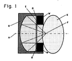
- FIG. 1 shows a patient's body K and a shock wave source, consisting of the wave generator W and the reflector R.
- the wave generator W is designed here as a cylinder, on the top surface D of which faces the reflector R, the radiating elements E (for example piezo elements or an electromagnetic coil) are arranged are.
- the elements E radiate the waves to the left towards the reflector R, from where they are focused on the focal point F, which lies on the central axis A of the reflector.
- the reflector R is filled with a liquid and sealed off from the body K with a membrane. Possible coupling pads are not shown here.
- the wave normals of shock waves, which are generated by the elements E, run to the left onto the reflector, are reflected from there, and meet at the focal point F are drawn in.
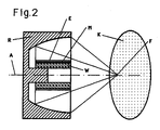
- FIG. 2 shows another embodiment in which the shock wave source has a cylindrical wave generator W, in which the radiating elements E are applied to the outer surface M of the wave generator.
- the elements E radiate radially outwards.
- the shock waves are in turn focused by the reflector R on the focal point F, which lies on the one hand in the patient's body K and on the other hand on the axis of symmetry A of the shock wave source.
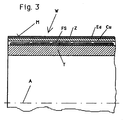
- FIG. 3 shows an embodiment of a wave generator as can be used in the shock wave source of FIG. 2.
- the wave generator W here consists of a ceramic or glass-like carrier T, around which a flat coil FS is wound.
- This coil can be constructed from discrete copper wire, it can also be made by copper-coated Kapton, which is appropriately etched so that a single copper strip remains, which was then wound up.
- This carrier T with flat coil FS is surrounded by a cylindrical membrane Z which surrounds the carrier T like a jacket M.
- the cylinder diaphragm Z in this version consists of a copper layer Cu and a stainless steel layer Ed.
- the insulation (not shown) between the tape reel FS and the copper membrane Z can consist of a separate layer of Kapton; it can be taken over by the copper-coated, etched-off Kapton foil itself with a suitable winding technique, as described with reference to FIG. 5.
- the gap visible in the figure between the insulation of the coil FS and the membrane Z should be designed as narrow as possible, ideally zero.
- FIG. 4 schematically shows a shock wave source with the radially radiating cylindrical wave generator W and the reflector R which surrounds it. Realizable size relationships of the components to one another and angles can be read from this figure.
- Figure 4 shows a scale (1: 2) implementation. The data in detail: - Coil length: 13 cm - Coil diameter: 6 cm - Focus length: 15 cm - aperture 42.40 - Paraboloid diameter: 27.4 cm
- the radiating surface corresponds to that of a flat one EMSE with a diameter of almost 18 cm.
- the finite radius of the cylinder source results in a minimal aperture angle, which, however, does not come about due to shading of the source. Extending the cylinder allows the surface to be enlarged, with the parabolic diameter increasing to the same extent.
- FIG. 5 shows schematically examples of two Kapton foils Ka, each carrying a strip of copper Cu.
- the copper strip is applied in the middle on the left Kapton foil, on the right on the right.
- the left Kapton layers then overlap over the previously wound copper layers Cu and serve as insulation there.
- two insulation layers then overlap.
Landscapes
- Physics & Mathematics (AREA)
- Engineering & Computer Science (AREA)
- Acoustics & Sound (AREA)
- Multimedia (AREA)
- Surgical Instruments (AREA)
- Apparatuses For Generation Of Mechanical Vibrations (AREA)
- Surface Acoustic Wave Elements And Circuit Networks Thereof (AREA)
- Magnetic Resonance Imaging Apparatus (AREA)
- Waveguides (AREA)
- Waveguide Aerials (AREA)
Abstract
Description
Die Erfindung betrifft eine Stosswellenquelle nach dem Oberbegriff des Anspruchs 1.The invention relates to a shock wave source according to the preamble of claim 1.
Aus der DE-PS 23 51 247 ist ein punktförmige Stosswellenquelle für Lithotripter bekannt.A punctiform shock wave source for lithotripters is known from DE-PS 23 51 247.
Eine flächige Stosswellenquelle ist aus der DE-OS 31 19 295 bekannt. Sie ist aus einzelnen Piezokeramikelementen aufgebaut. Diese flächige Quelle ist entweder selbstfokussierend als Kugelkalotte ausgebildet worden oder sie ist mit einem Abbildungssystem wie Reflektoren oder Linsen zur notwendigen Fokussierung versehen. Die Ausbildung einer Stoßfront aus einem Schalldruckpuls bei der flächenhaften Quelle ist durch nichtlineare Ausbreitung bei hinreichender Intensität gegeben.A flat shock wave source is known from DE-OS 31 19 295. It is made up of individual piezoceramic elements. This area source is either self-focusing as a spherical cap or it is provided with an imaging system such as reflectors or lenses for the necessary focusing. The formation of a shock front from a sound pressure pulse at the area source is given by nonlinear propagation with sufficient intensity.
Aus der DE-OS 34 47 440 ist eine Stosswellenquelle für die berührungsfreie Lithotripsie bekannt, die einen flächigen Wellenerzeuger (ein elektromagnetisches Stoßwellenrohr) und einen parabelförmigen Reflektor aufweist. Dieser fokussiert die ebene Stosswelle auf das Konkrement im Körper des Patienten. Diese Stosswellenquelle bildet den Oberbegriff des Anspruchs 1.From DE-OS 34 47 440 a shock wave source for non-contact lithotripsy is known, which has a flat wave generator (an electromagnetic shock wave tube) and a parabolic reflector. This focuses the flat shock wave on the concretion in the patient's body. This shock wave source forms the preamble of claim 1.
Um eine gute Zerkleinerungseffizienz im vivo bei geringen Neben- und Nachwirkungen der Behandlung zu erreichen, lassen sich folgende wesentliche technische Anforderungen an ein Stosswellensystem ableiten:
- hohe Dynamik in der Leistung
- gute Fokussierung möglichst unipolarer Pulse
- wenig Druck und vor allem Zug beim Eintritt in den Patienten
- gute und genaue Ortungsmöglichkeiten mittels Ultraschall und/oder Röntgen
- kompakter Aufbau
- hohe Lebensdauer.In order to achieve good shredding efficiency in vivo with few side effects and after-effects of the treatment, the following essential technical requirements can be derived from a shock wave system:
- high dynamic performance
- Good focusing of the most unipolar pulses possible
- little pressure and especially tension when entering the patient
- Good and accurate location options using ultrasound and / or X-ray
- compact construction
- long life span.
Diese Anforderungen werden von den derzeit klinisch eingesetzten Systemen nicht vollständig bzw. nicht simultan erfüllt. So besitzen gegenwärtig eingesetzte punktförmige Quellen wohl eine hohe Leistung, aber nur einen begrenzten Dynamikbereich zu niedrigen Leistungen hin. Außerdem können sich die Stosswelle und zentrale (axiale) Ultraschall-Ortungsvorrichtungen stören. Selbstfokussierende Piezosysteme sind wegen der geringen Intensität an der Quelle relativ groß und haben daher nur wenig Platz für externe Röntgenortung. Ebene elektromagnetische Spulensysteme besitzen ausreichende Leistungsdichten an der Quelle, lassen sich aber nur eingeschränkt hochaperturig bei Linsenfokussierung auslegen. Selbstfokussierende elektromagnetische Kalottensysteme haben oft nicht die erwünschten Standzeiten.The systems currently used clinically do not meet these requirements fully or simultaneously. So point sources currently used probably have a high power, but only a limited dynamic range towards low powers. In addition, the shock wave and central (axial) ultrasonic location devices can interfere. Self-focusing piezo systems are relatively large due to the low intensity at the source and therefore have little space for external X-ray location. Level electromagnetic coil systems have sufficient power densities at the source, but can only be designed to a limited extent with high aperture when focusing lenses. Self-focusing electromagnetic calotte systems often do not have the desired service life.
Es ist daher Aufgabe der Erfindung, eine Stosswellenquelle für die Lithotripsie vorzuschlagen, die möglichst viele der oben genannten Anforderungen gleichzeitig erfüllt.It is therefore an object of the invention to propose a shock wave source for lithotripsy that fulfills as many of the above requirements as possible.
Erfindungsgemäß wird eine Stosswellenquelle mit den Merkmalen des Anspruchs 1 vorgeschlagen.According to the invention, a shock wave source with the features of claim 1 is proposed.
Sie erfüllt die Anforderungen nach ausreichender Leistung, ausreichender Leistungsdynamik, Hochaperturigkeit und Integration der Ortungssysteme gleichzeitig.
Benutzt wird die Eigenschaft einer Parabel bzw. eines Paraboloids, eine ebene Wellenfront auf einen Brennpunkt abzubilden.It fulfills the requirements for sufficient performance, sufficient performance dynamics, high aperture and integration of the location systems at the same time.
The property of a parabola or a paraboloid is used to map a flat wavefront to a focal point.
In einer Ausführung wird die Quelle ringförmig in der Einfallsebene des Paraboloids angeordnet, so daß sich wegen der endlichen Dicke eine Art "Lochzylinder" ergibt. Das Loch in der Mitte ist notwendig, da der Fokus quellenseitig liegt. Außerdem ist die axiale Öffnung, das heißt die ringförmige Auslegung der Quelle sinnvoll, da bei einem bestimmten minimalen Aperturwinkel der reflektierte Schall vom oberen Paraboloidrand auf die Quelle reflektiert wird und damit für die Fokussierung verloren ginge.
Die reflektierte, sphärisch konvergente Wellenfront ist also hochaperturig fokussiert mit freiem Zentralbereich, der dann z.B. für Ortungssysteme zur Verfügung steht. Die Möglichkeiten der Anordnung sind sehr variabel - so kann die effektive Fokustiefe reduziert werden, wenn der Ring der Quelle einen so grossen Innenradius hat, daß er quasi um den Patienten gelegt werden kann. Der Fokus liegt dann zwischen der Quelle und dem Reflektor. Hier ist der limitierende Faktor für den Innenradius nicht die Selbstabschattung der Quelle, sondern der Platz für den Patienten oder das zu behandelnde Körperteil des Patienten im Raum zwischen Reflektor und Quelle.In one embodiment, the source is arranged in a ring in the plane of incidence of the paraboloid, so that a kind of "perforated cylinder" results because of the finite thickness. The hole in the middle is necessary because the focus is on the source side. In addition, the axial opening, i.e. the ring-shaped design of the source, makes sense, since at a certain minimum aperture angle, the reflected sound is reflected from the upper paraboloid edge onto the source and would therefore be lost for focusing.
The reflected, spherically convergent wavefront is therefore focused on a high aperture with a free central area, which is then available, for example, for location systems. The possibilities of the arrangement are very variable - so the effective depth of focus can be reduced if the ring of the source has such a large inner radius that it can be put around the patient. The focus is then between the source and the reflector. The limiting factor for the inner radius here is not the shading of the source itself, but the space for the patient or the part of the patient to be treated in the space between the reflector and the source.
In einer anderen Ausführung liegt der Fokus hinter der Stosswellenquelle. Die Stosswellen laufen durch das Loch in der Mitte auf diesen Punkt zu.
Als Vorteile dieser Quellen/Reflektorgeometrie lassen sich nennen:
- Hohe Variabilität und Flexibilität bezüglich Größe der Quelle, so daß die ebenen Flächenquelle nach Leistungsanforderungen und Leistungsmöglichkeiten ausgelegt werden kann.
- Die Anordnung ist gleichermaßen für piezoelektrische als auch für elektromagnetische Schallpulserzeugung einsetzbar.
- Die ebene Form der Quelle vereinfacht eine Hochleistungsauslegung (Isolierung, Kontaktierung).
- Gute Fokussierung durch hohe Apertur und Schallfeldfreiheit in der Mitte.
- Die zentrale Schallfeldfreiheit lässt genügend Platz für Ortungssysteme (Ultraschall und/oder Röntgen).
- Ortung und Stosswelle stören sich nicht.
- Reduktion der axialen Druck- und insbesondere Zuganteile durch zentrale Schallfeldfreiheit.In another version, the focus is behind the Shock wave source. The shock waves run through the hole in the middle towards this point.
Advantages of this source / reflector geometry can be mentioned:
- High variability and flexibility regarding the size of the source, so that the flat surface source can be designed according to performance requirements and performance options.
- The arrangement can be used equally for piezoelectric as well as for electromagnetic sound pulse generation.
- The flat shape of the source simplifies high-performance design (insulation, contacting).
- Good focusing due to high aperture and sound field freedom in the middle.
- The central freedom from the sound field leaves enough space for positioning systems (ultrasound and / or X-ray).
- Location and shock wave do not interfere.
- Reduction of the axial pressure and, in particular, tensile components due to central freedom from sound fields.
Eine andere Ausführung der Erfindung besteht darin, daß eine zylinderförmige Quelle verwendet wird, die mit ihrer Mantelfläche auf den sie umgebenden Reflektor abstrahlt. Dieser Reflektor wird durch Rotation einer Teilparabel um eine Linie erzeugt, die senkrecht durch den Fokuspunkt der Parabel verläuft und gleichzeitig die Symmetrieachse der zylinderförmigen Quelle darstellt. Dabei wird eine Zylinderwelle durch den radial nach außen Schall abstrahlenden Zylindermantel erzeugt. Diese Anordnung kann z.B. durch ein kompaktes Rohr aus Piezokeramik realisiert werden, auf dessen Mantelfläche die Piezokeramikelemente angeordnet sind. Diese Geometrie erlaubt hinsichtlich Fokuslänge und Apertur eine hohe Variabilität, ähnlich der Auslegung des Ellipsoid-Reflektors bei der Unterwasserfunkenentladung, insbesondere wenn die Quelle eine hohe Leistungsdichte besitzt.Another embodiment of the invention is that a cylindrical source is used which emits with its outer surface onto the reflector surrounding it. This reflector is generated by rotating a partial parabola around a line that is perpendicular to the focal point of the Parabola runs and at the same time represents the axis of symmetry of the cylindrical source. A cylinder shaft is generated by the cylinder jacket which radiates sound radially outwards. This arrangement can be realized, for example, by a compact tube made of piezoceramic, on the lateral surface of which the piezoceramic elements are arranged. This geometry allows a high variability in terms of focus length and aperture, similar to the design of the ellipsoid reflector for underwater spark discharge, especially if the source has a high power density.
Möglich ist auch - für höhe Leistungen bei kompaktem Aufbau - eine elektromagnetische Quelle in Zylindergeometrie, das heißt eine Längsspule mit leitfähigem Zylindermantel als abstrahlender Membran. Die Schallquelle besteht dann aus Spule, Isolierung und einem leitfähigen Außenzylinder, der bei Beaufschlagung der Spule mit Strom oder Pulsen durch die abstossende Kraftwirkung zwischen primärem und sekundärseitig induziertem Strom radial nach außen ausgelenkt wird. Die technischen Probleme wie Enge und genaue Kopplung zwischen Spule, Membran und Isolierung, sowie die Ausdehnung in umlaufender Richtung bei radialer Ausdehnung (Abstrahlung) sind beherrschbar. Diese bestimmen neben der notwendigen Gesamtfläche den minimalen Radius.It is also possible - for high performance with a compact design - an electromagnetic source in cylinder geometry, i.e. a longitudinal coil with a conductive cylinder jacket as a radiating membrane. The sound source then consists of a coil, insulation and a conductive outer cylinder which is deflected radially outward when the coil is subjected to current or pulses due to the repulsive force effect between the primary and secondary-induced current. The technical problems such as tightness and precise coupling between the coil, membrane and insulation, as well as the expansion in the circumferential direction with radial expansion (radiation) are manageable. In addition to the necessary total area, these determine the minimum radius.
In einer Ausführungsform wird eine einlagige Zylinderspule (Flachspule) verwendet, die aus flachen Leiterbahnen gewickelt sein kann, die auf einen Isolatorträger aufgebracht sind. Die zylindrische Membran kann z.B. aus einer Kupferschicht und einer Edelstahlschicht zusammengesetzt sein. Die Kupferschicht sorgt für gute elektrische Eigenschaften, der Edelstahlmantel für gute mechanische Festigkeit.In one embodiment, a single-layer cylindrical coil (flat coil) is used, which can be wound from flat conductor tracks that are applied to an insulator carrier. The cylindrical membrane can, for example, be composed of a copper layer and a stainless steel layer. The copper layer ensures good electrical properties, the stainless steel jacket provides good mechanical strength.
Letztere ist aber nicht zwingend notwendig.However, the latter is not absolutely necessary.
Es ist ebenso möglich, die zylindrische Membran aus mehreren Metallschichten aufzubauen, die durch Isolationsfolien voneinander getrennt sind, so wie es in der deutschen Patentanmeldung P 37 43 822 bereits vorgeschlagen wurde. Dadurch können Wirbelstromverluste verringert werden.It is also possible to construct the cylindrical membrane from a plurality of metal layers which are separated from one another by insulating foils, as has already been proposed in German patent application P 37 43 822. This can reduce eddy current losses.
Eine mögliche Realisierung besteht z.B. in der Verwendung von z.B. 10 mm breiten Kupfer-Flachband mit einer Dicke von z.B. 0,2 mm, abgestimmt auf die Eindringtiefe des Feldes bei gegebener Pulsdauer sowie durch die notwendige mechanische Stabilität der Zylindermantelmembran. Die Dicke der Isolierung bestimmt dabei die Hochspannungsfestigkeit.One possible implementation is e.g. in the use of e.g. 10 mm wide copper ribbon with a thickness of e.g. 0.2 mm, matched to the penetration depth of the field for a given pulse duration and the necessary mechanical stability of the cylinder jacket membrane. The thickness of the insulation determines the high voltage strength.
Ein beispielhaft verwendbares mit Kapton isoliertes Kupfer-Flachband sollte dabei zur Isolierfestigkeit der Spule in Längsrichtung (Wickelrichtung) mindestens dreimal so breit sein, wie die Kupferbahn. Die Membran kann dann spaltfrei auf die Spule aufgeschrumpft werden. Dies kann z.B. durch Erhitzen, Aufschieben und anschliessendes Auskühlen erfolgen.An exemplary usable copper flat tape insulated with Kapton should be at least three times as wide as the copper track for the insulation strength of the coil in the longitudinal direction (winding direction). The membrane can then be shrunk onto the coil without any gaps. This can e.g. by heating, sliding open and then cooling.
Die Erfindung wird anhand von fünf Figuren näher erläutert.The invention is explained in more detail with reference to five figures.
Es zeigen:
- Figuren 1 und 2 zwei erfindungsgemäße Ausführungen von Stosswellenquellen,
- Figur 3 eine Ausführung eines Wellenerzeugers, wie er in der Stosswellenquelle der Figur 2 einsetzbar ist,
- Figur 4 eine Stosswellenquelle mit grösserer Öffnung,
- Figur 5 zwei Folien, aus denen je eine Spule wickelbar ist.
- FIGS. 1 and 2 show two versions of shock wave sources according to the invention,
- FIG. 3 shows an embodiment of a wave generator as can be used in the shock wave source of FIG. 2,
- FIG. 4 shows a shock wave source with a larger opening,
- Figure 5 two films, each of which a coil can be wound is.
Figur 1 zeigt einen Patientenkörper K und eine Stosswellenquelle, bestehend aus dem Wellenerzeuger W und dem Reflektor R. Der Wellenerzeuger W ist hier als Zylinder ausgebildet, auf dessen dem Reflektor R zugewandten Deckfläche D die abstrahlenden Elemente E (z.B. Piezoelemente oder eine elektromagnetische Spule) angeordnet sind. Die Elemente E strahlen die Wellen nach links zum Reflektor R hin ab, von wo sie auf den Brennpunkt F, der auf der Mittelachse A des Reflektors liegt, fokussiert werden. Der Reflektor R ist mit einer Flüssigkeit gefüllt und mit einer Membran gegenüber dem Körper K abgeschlossen. Eventuelle Ankoppelkissen sind hier nicht gezeigt. Eingezeichnet sind die Wellennormalen von Stosswellen, die von den Elementen E erzeugt werden, nach links auf den Reflektor laufen, von dort reflektiert werden, und sich im Brennpunkt F treffen.FIG. 1 shows a patient's body K and a shock wave source, consisting of the wave generator W and the reflector R. The wave generator W is designed here as a cylinder, on the top surface D of which faces the reflector R, the radiating elements E (for example piezo elements or an electromagnetic coil) are arranged are. The elements E radiate the waves to the left towards the reflector R, from where they are focused on the focal point F, which lies on the central axis A of the reflector. The reflector R is filled with a liquid and sealed off from the body K with a membrane. Possible coupling pads are not shown here. The wave normals of shock waves, which are generated by the elements E, run to the left onto the reflector, are reflected from there, and meet at the focal point F are drawn in.
Figur 2 zeigt eine andere Ausführung, bei der die Stosswellenquelle einen zylinderförmigen Wellenerzeuger W aufweist, bei dem die abstrahlenden Elemente E auf der Mantelfläche M des Wellenerzeugers aufgebracht sind. Die Elemente E strahlen radial nach außen ab. Die Stosswellen werden vom Reflektor R wiederum auf den Brennpunkt F fokussiert, der zum einen im Körper K des Patienten liegt und zum anderen auf der Symmetrieachse A der Stosswellenquelle.FIG. 2 shows another embodiment in which the shock wave source has a cylindrical wave generator W, in which the radiating elements E are applied to the outer surface M of the wave generator. The elements E radiate radially outwards. The shock waves are in turn focused by the reflector R on the focal point F, which lies on the one hand in the patient's body K and on the other hand on the axis of symmetry A of the shock wave source.
Nicht gezeigt sind hier die Füllung der Stosswellenquelle mit schalleitendem Medium und eventuelle Ankopplungen über Kissen oder ähnliches.The filling of the shock wave source with sound-conducting medium and possible connections via pillows or the like are not shown here.
Figur 3 zeigt eine Ausführung eines Wellenerzeugers, wie er bei der Stosswellenquelle der Figur 2 einsetzbar ist.FIG. 3 shows an embodiment of a wave generator as can be used in the shock wave source of FIG. 2.
Der Wellenerzeuger W besteht hier aus einem keramischen oder glasartigen Träger T, um den eine Flachspule FS gewickelt ist. Diese Spule kann aus diskretem Kupferdraht aufgebaut sein, sie kann auch durch kupferbeschichtetes Kapton, das entsprechend geätzt ist, so daß ein einziger Kupferstreifen übrigbleibt, der anschließend aufgewickelt wurde, hergestellt sein. Dieser Träger T mit Flachspule FS wird umgeben von einer zylindrischen Membran Z, die den Träger T wie ein Mantel M umgibt. Die Zylindermembran Z besteht in dieser Ausführung aus einer Kupferschicht Cu und einer Edelstahlschicht Ed.The wave generator W here consists of a ceramic or glass-like carrier T, around which a flat coil FS is wound. This coil can be constructed from discrete copper wire, it can also be made by copper-coated Kapton, which is appropriately etched so that a single copper strip remains, which was then wound up. This carrier T with flat coil FS is surrounded by a cylindrical membrane Z which surrounds the carrier T like a jacket M. The cylinder diaphragm Z in this version consists of a copper layer Cu and a stainless steel layer Ed.
Die nicht eingezeichnete Isolierung zwischen Bandspule FS und Kupfermembran Z kann aus einer separaten Schicht Kapton bestehen; sie kann bei geeigneter Wickeltechnik der kupferbeschichteten abgeätzten Kaptonfolie von dieser selbst übernommen werden, wie anhand von Figur 5 geschildert. Der in der Figur sichtbare Spalt zwischen der Isolierung der Spule FS und der Membran Z ist möglichst eng auszulegen, ideal gleich null.The insulation (not shown) between the tape reel FS and the copper membrane Z can consist of a separate layer of Kapton; it can be taken over by the copper-coated, etched-off Kapton foil itself with a suitable winding technique, as described with reference to FIG. 5. The gap visible in the figure between the insulation of the coil FS and the membrane Z should be designed as narrow as possible, ideally zero.
Figur 4 zeigt schematisch eine Stosswellenquelle mit dem radial abstrahlenden zylindrischen Wellenerzeuger W und dem Reflektor R, der ihn umgibt. Aus dieser Figur können realisierbare Größenverhältnisse der Bauteile zueinander und Winkel abgelesen werden. Figur 4 zeigt eine maßstabsgetreue (1:2) Realisierung. Die Daten im einzelnen:
- Länge Spule: 13 cm
- Durchmesser Spule: 6 cm
- Fokuslänge: 15 cm
- Apertur 42.4⁰
- Durchmesser Paraboloid: 27.4 cm
Die abstrahlende Fläche entspricht dabei der einer ebenen EMSE mit fast 18 cm Durchmesser. Durch den endlichen Radius der Zylinderquelle ergibt sich ein minimaler Aperturwinkel, der allerdings nicht durch Abschattung der Quelle zu Stande kommt. Verlängerung des Zylinders ermöglicht eine Vergrösserung der Fläche, wobei sich der Parabeldurchmesser im selben Maße vergrössert. Ortung ist unter Umständen durch die zentrale Öffnung der Quelle möglich. Die radial abgestrahlten Wellen werden vom paraboidförmigen Reflektor R auf den Brennpunkt F auf der Spulenachse A gelenkt. Der Zusammenhang zwischen Öffnungswinkel φ und Abstand:Linienquelle - Fokus h lautet hier:
h = p·cos φ / (1+sin φ )
wobei p der Parabelparameter ist (y²=2px). Der Fokus liegt bei x=p/2. Äquivalent dazu ist
tan φ = (p/h-h/p)/2FIG. 4 schematically shows a shock wave source with the radially radiating cylindrical wave generator W and the reflector R which surrounds it. Realizable size relationships of the components to one another and angles can be read from this figure. Figure 4 shows a scale (1: 2) implementation. The data in detail:
- Coil length: 13 cm
- Coil diameter: 6 cm
- Focus length: 15 cm
- aperture 42.4⁰
- Paraboloid diameter: 27.4 cm
The radiating surface corresponds to that of a flat one EMSE with a diameter of almost 18 cm. The finite radius of the cylinder source results in a minimal aperture angle, which, however, does not come about due to shading of the source. Extending the cylinder allows the surface to be enlarged, with the parabolic diameter increasing to the same extent. Localization may be possible through the central opening of the source. The radially emitted waves are directed by the paraboid reflector R to the focal point F on the coil axis A. The relationship between aperture angle φ and distance: line source - focus h is here:
h = pcos φ / (1 + sin φ)
where p is the parabola parameter (y² = 2px). The focus is on x = p / 2. Is equivalent to this
tan φ = (p / hh / p) / 2
Ein Vorteil dieser Geometrie besteht darin, aus einer kleinen, kompakten Flächenquelle eine hohe Apertur und damit gute Fokussierung zu erzielen.
Die Druckamplitude f( φ ) in der Apertur folgt dem Gesetz für eine Zylinderwelle und ist im Zentralbereich überhöht:
f(φ ) ∼ (sin φ (1+sin φ ))-1/2 One advantage of this geometry is that you can achieve a high aperture and therefore good focusing from a small, compact surface source.
The pressure amplitude f (φ) in the aperture follows the law for a cylinder shaft and is excessive in the central area:
f (φ) ∼ (sin φ (1 + sin φ)) -1/2
Figur 5 zeigt schematisch Beispiele für zwei Kaptonfolien Ka, die jeweils einen Streifen Kupfer Cu tragen. Auf der linken Kaptonfolie ist der Kupferstreifen in der Mitte aufgebracht, bei der Rechten rechts. Durch schraubenförmiges Aufwickeln jeder der Folien auf einen zylindrischen Träger, so daß eine Kupferschicht neben der anderen liegt, lässt sich je eine Flachspule herstellen. Dabei überlappen dann die linken Kaptonschichten über die vorher gewickelten Kupferschichten Cu und dienen dort als Isolierung. Beim Aufwickeln der rechts gezeigten Folie überlappen dann zwei Isolationsschichten.Figure 5 shows schematically examples of two Kapton foils Ka, each carrying a strip of copper Cu. The copper strip is applied in the middle on the left Kapton foil, on the right on the right. By helically winding each of the foils onto a cylindrical support so that one copper layer lies next to the other produce a flat coil each. The left Kapton layers then overlap over the previously wound copper layers Cu and serve as insulation there. When the film shown on the right is wound up, two insulation layers then overlap.
Claims (9)
Applications Claiming Priority (2)
| Application Number | Priority Date | Filing Date | Title |
|---|---|---|---|
| DE3907605 | 1989-03-09 | ||
| DE3907605A DE3907605C2 (en) | 1989-03-09 | 1989-03-09 | Shock wave source |
Publications (3)
| Publication Number | Publication Date |
|---|---|
| EP0386479A2 true EP0386479A2 (en) | 1990-09-12 |
| EP0386479A3 EP0386479A3 (en) | 1991-05-29 |
| EP0386479B1 EP0386479B1 (en) | 1996-10-23 |
Family
ID=6375909
Family Applications (1)
| Application Number | Title | Priority Date | Filing Date |
|---|---|---|---|
| EP90102352A Expired - Lifetime EP0386479B1 (en) | 1989-03-09 | 1990-02-07 | Shock wave generator |
Country Status (5)
| Country | Link |
|---|---|
| US (1) | US5174280A (en) |
| EP (1) | EP0386479B1 (en) |
| JP (1) | JPH0832265B2 (en) |
| DE (1) | DE3907605C2 (en) |
| ES (1) | ES2096564T3 (en) |
Cited By (1)
| Publication number | Priority date | Publication date | Assignee | Title |
|---|---|---|---|---|
| US11065645B2 (en) | 2015-04-24 | 2021-07-20 | Les Solutions Medicales Soundbite Inc. | Method and system for generating mechanical pulses |
Families Citing this family (48)
| Publication number | Priority date | Publication date | Assignee | Title |
|---|---|---|---|---|
| DE3835318C1 (en) * | 1988-10-17 | 1990-06-28 | Storz Medical Ag, Kreuzlingen, Ch | |
| DE4110102A1 (en) * | 1991-03-27 | 1992-10-01 | Siemens Ag | Electromagnetically driven pressure pulse source for medical use - has electrically conducting membrane formed as annular array of zones activated by drive coils having variable timings |
| US7189209B1 (en) | 1996-03-29 | 2007-03-13 | Sanuwave, Inc. | Method for using acoustic shock waves in the treatment of a diabetic foot ulcer or a pressure sore |
| US6390995B1 (en) | 1997-02-12 | 2002-05-21 | Healthtronics Surgical Services, Inc. | Method for using acoustic shock waves in the treatment of medical conditions |
| US6869407B2 (en) * | 2001-09-12 | 2005-03-22 | Moshe Ein-Gal | Acoustic wave device |
| US7048699B2 (en) * | 2001-09-12 | 2006-05-23 | Moshe Ein-Gal | Non-cylindrical acoustic wave device |
| US7311677B1 (en) * | 2002-06-26 | 2007-12-25 | Fields John G | Energy concentrator system and method |
| US8257282B2 (en) * | 2004-02-19 | 2012-09-04 | General Patent, Llc | Pressure pulse/shock wave apparatus for generating waves having plane, nearly plane, convergent off target or divergent characteristics |
| US20060100549A1 (en) * | 2004-10-22 | 2006-05-11 | Reiner Schultheiss | Pressure pulse/shock wave apparatus for generating waves having nearly plane or divergent characteristics |
| US7559904B2 (en) * | 2003-07-17 | 2009-07-14 | Moshe Ein-Gal | Shockwave generating system |
| US7338513B2 (en) * | 2003-10-30 | 2008-03-04 | Cambridge Endoscopic Devices, Inc. | Surgical instrument |
| US20050165275A1 (en) * | 2004-01-22 | 2005-07-28 | Kenneth Von Felten | Inspection device insertion tube |
| US7507213B2 (en) * | 2004-03-16 | 2009-03-24 | General Patent Llc | Pressure pulse/shock wave therapy methods for organs |
| US7537572B2 (en) * | 2004-10-22 | 2009-05-26 | General Patent, Llc | Treatment or pre-treatment for radiation/chemical exposure |
| US7497836B2 (en) * | 2004-10-22 | 2009-03-03 | General Patent Llc | Germicidal method for treating or preventing sinusitis |
| US7601127B2 (en) * | 2004-10-22 | 2009-10-13 | General Patent, Llc | Therapeutic stimulation of genital tissue or reproductive organ of an infertility or impotence diagnosed patient |
| US7578796B2 (en) * | 2004-10-22 | 2009-08-25 | General Patent Llc | Method of shockwave treating fish and shellfish |
| US7600343B2 (en) * | 2004-10-22 | 2009-10-13 | General Patent, Llc | Method of stimulating plant growth |
| US7497835B2 (en) * | 2004-10-22 | 2009-03-03 | General Patent Llc | Method of treatment for and prevention of periodontal disease |
| US7497834B2 (en) * | 2004-10-22 | 2009-03-03 | General Patent Llc | Germicidal method for eradicating or preventing the formation of biofilms |
| US7544171B2 (en) * | 2004-10-22 | 2009-06-09 | General Patent Llc | Methods for promoting nerve regeneration and neuronal growth and elongation |
| US7988648B2 (en) * | 2005-03-04 | 2011-08-02 | General Patent, Llc | Pancreas regeneration treatment for diabetics using extracorporeal acoustic shock waves |
| DE102005017724A1 (en) * | 2005-04-15 | 2006-11-09 | Ast Gmbh | Focusing device for a device for generating shockwaves |
| US8277397B2 (en) * | 2005-06-15 | 2012-10-02 | Moshe Ein-Gal | Wave generating device with inner reflector |
| US20070239074A1 (en) * | 2006-02-15 | 2007-10-11 | Moshe Ein-Gal | Line focusing acoustic wave source |
| US7610079B2 (en) * | 2006-07-25 | 2009-10-27 | Ast Gmbh | Shock wave imaging system |
| DE102006050781A1 (en) * | 2006-10-27 | 2008-04-30 | Ast Gmbh | Device for the spatial positioning of a device |
| KR100840771B1 (en) * | 2006-11-02 | 2008-06-23 | 조성찬 | Apparatus for generating shock wave using piezoelectric element |
| US8529451B2 (en) * | 2007-10-01 | 2013-09-10 | General Patent, Llc | Shock wave coupling adapter and method of use |
| US20100036294A1 (en) | 2008-05-07 | 2010-02-11 | Robert Mantell | Radially-Firing Electrohydraulic Lithotripsy Probe |
| US9913748B2 (en) | 2009-10-30 | 2018-03-13 | Avner Spector | Method and apparatus for treatment of erectile dysfunction with extracorporeal shockwaves |
| WO2012108854A2 (en) * | 2009-12-22 | 2012-08-16 | Phoenix Science & Technology, Inc. | Sparker array source |
| US7918309B1 (en) * | 2010-07-07 | 2011-04-05 | Robert Kenneth Vierra | Apparatus for producing a continuous sonic boom |
| WO2012025833A2 (en) | 2010-08-27 | 2012-03-01 | Socpra- Sciences Et Génie, S.E.C. | Mechanical wave generator and method thereof |
| DE102011011541A1 (en) * | 2011-02-17 | 2012-08-23 | Fraunhofer-Gesellschaft zur Förderung der angewandten Forschung e.V. | Ultrasonic transducer arrangement, has concave reflector surface whose focus region lies in subsequent semi-infinite space rear to ultrasonic transducer that turns transducer surface, and reflecting body provided with reflector surface |
| FR2973685B1 (en) * | 2011-04-05 | 2014-11-28 | Eye Tech Care | ULTRASOUND OCULAR THERAPY DEVICE WITH REFLECTOR |
| WO2014140715A2 (en) | 2013-03-11 | 2014-09-18 | Northgate Technologies Inc. | Unfocused electrohydraulic lithotripter |
| FR3007926B1 (en) * | 2013-06-27 | 2016-01-08 | Areva Np | ULTRASONIC TRANSDUCER |
| US11389371B2 (en) | 2018-05-21 | 2022-07-19 | Softwave Tissue Regeneration Technologies, Llc | Acoustic shock wave therapeutic methods |
| US11389373B2 (en) | 2016-04-18 | 2022-07-19 | Softwave Tissue Regeneration Technologies, Llc | Acoustic shock wave therapeutic methods to prevent or treat opioid addiction |
| US11458069B2 (en) | 2016-04-18 | 2022-10-04 | Softwave Tissue Regeneration Technologies, Llc | Acoustic shock wave therapeutic methods to treat medical conditions using reflexology zones |
| US11389372B2 (en) | 2016-04-18 | 2022-07-19 | Softwave Tissue Regeneration Technologies, Llc | Acoustic shock wave therapeutic methods |
| US11389370B2 (en) | 2016-04-18 | 2022-07-19 | Softwave Tissue Regeneration Technologies, Llc | Treatments for blood sugar levels and muscle tissue optimization using extracorporeal acoustic shock waves |
| US10441499B1 (en) | 2018-10-18 | 2019-10-15 | S-Wave Corp. | Acoustic shock wave devices and methods for generating a shock wave field within an enclosed space |
| US10441498B1 (en) | 2018-10-18 | 2019-10-15 | S-Wave Corp. | Acoustic shock wave devices and methods for treating erectile dysfunction |
| US10695588B1 (en) | 2018-12-27 | 2020-06-30 | Sonicon Inc. | Cranial hair loss treatment using micro-energy acoustic shock wave devices and methods |
| EP3682822B1 (en) * | 2019-01-18 | 2024-05-08 | Storz Medical AG | Combined shockwave and ultrasound source |
| EP4052665A1 (en) | 2021-03-04 | 2022-09-07 | Storz Medical AG | Diffuser for a shockwave transducer |
Citations (5)
| Publication number | Priority date | Publication date | Assignee | Title |
|---|---|---|---|---|
| US2855526A (en) * | 1955-10-24 | 1958-10-07 | Aeroprojects Inc | Apparatus for generating ultrasonic energy of high intensity |
| FR2164496A1 (en) * | 1971-12-23 | 1973-08-03 | Commissariat Energie Atomique | |
| GB1410212A (en) * | 1972-05-16 | 1975-10-15 | Secr Defence | Method of and apparatus for ultrasonic testing |
| SU1393489A1 (en) * | 1986-02-19 | 1988-05-07 | Опытно-конструкторское бюро "Горизонт" | Acoustic focusing converter |
| EP0387858A1 (en) * | 1989-03-14 | 1990-09-19 | Storz Medical Ag | Apparatus to generate focused acoustic waves |
Family Cites Families (20)
| Publication number | Priority date | Publication date | Assignee | Title |
|---|---|---|---|---|
| DE1076413B (en) * | 1954-06-02 | 1960-02-25 | Fruengel Frank Dr Ing | Impact sound source |
| US3451260A (en) * | 1966-03-23 | 1969-06-24 | Us Health Education & Welfare | Apparatus for ultrasonic scanning using an elliptic reflecting system |
| US4241432A (en) * | 1967-04-21 | 1980-12-23 | The United States Of America As Represented By The Secretary Of The Navy | Transducer-reflector system |
| US3755698A (en) * | 1972-04-25 | 1973-08-28 | Us Navy | Free-flooded ring transducer with slow wave guide |
| US3895188A (en) * | 1972-06-21 | 1975-07-15 | Everett L Ingraham | Sound collecting device |
| DE2921444B2 (en) * | 1979-05-26 | 1981-04-23 | Richard Wolf Gmbh, 7134 Knittlingen | Device for the contactless crushing of kidney stones or the like. |
| DE3119295A1 (en) * | 1981-05-14 | 1982-12-16 | Siemens AG, 1000 Berlin und 8000 München | DEVICE FOR DESTROYING CONCRETE IN BODIES |
| AU550225B2 (en) * | 1982-05-26 | 1986-03-06 | Ontario Cancer Institute, The | Ultrasonic imaging device |
| DE3320935A1 (en) * | 1983-06-09 | 1984-12-13 | Siemens AG, 1000 Berlin und 8000 München | ULTRASONIC SENSOR |
| NL8400504A (en) * | 1984-02-16 | 1985-09-16 | Optische Ind De Oude Delft Nv | DEVICE FOR NON-TOGETIC GRINDING OF CONCREMENTS IN A BODY. |
| DE3447440A1 (en) * | 1984-12-27 | 1986-07-03 | Siemens AG, 1000 Berlin und 8000 München | SHOCK SHAFT PIPE FOR THE CRUSHING OF CONCRETE |
| DE3501838A1 (en) * | 1985-01-21 | 1986-07-24 | Siemens AG, 1000 Berlin und 8000 München | DEVICE FOR THE GENERATION OF TIMED SHOCK SHAFTS |
| DE3505855A1 (en) * | 1985-02-20 | 1986-08-21 | Siemens AG, 1000 Berlin und 8000 München | Method for producing a flat coil unit |
| JPS62336A (en) * | 1985-06-26 | 1987-01-06 | 八千代田工業株式会社 | Apparatus for crushing stone from outside of body by shock wave in liquid |
| EP0209053A3 (en) * | 1985-07-18 | 1987-09-02 | Wolfgang Prof. Dr. Eisenmenger | Method and apparatus for the non-contacting disintegration of concretions in a living body |
| DE8523751U1 (en) * | 1985-08-19 | 1986-12-18 | Siemens AG, 1000 Berlin und 8000 München | Device for the sonication of pathological changes in a patient |
| SU1405885A2 (en) * | 1986-05-27 | 1988-06-30 | Опытно-конструкторское бюро "Горизонт" | Acoustic focusing transducer |
| DE8709363U1 (en) * | 1987-07-07 | 1988-11-03 | Siemens AG, 1000 Berlin und 8000 München | Shock wave source |
| DE8710118U1 (en) * | 1987-07-23 | 1988-11-17 | Siemens AG, 1000 Berlin und 8000 München | Shock wave generator for a device for the contactless destruction of concretions in the body of a living being |
| DE3743822A1 (en) * | 1987-12-23 | 1989-07-13 | Dornier Medizintechnik | ELECTROMAGNETIC SHAFT SOURCE |
-
1989
- 1989-03-09 DE DE3907605A patent/DE3907605C2/en not_active Expired - Fee Related
-
1990
- 1990-02-07 ES ES90102352T patent/ES2096564T3/en not_active Expired - Lifetime
- 1990-02-07 EP EP90102352A patent/EP0386479B1/en not_active Expired - Lifetime
- 1990-03-05 JP JP2053470A patent/JPH0832265B2/en not_active Expired - Lifetime
- 1990-03-09 US US07/491,315 patent/US5174280A/en not_active Expired - Lifetime
Patent Citations (5)
| Publication number | Priority date | Publication date | Assignee | Title |
|---|---|---|---|---|
| US2855526A (en) * | 1955-10-24 | 1958-10-07 | Aeroprojects Inc | Apparatus for generating ultrasonic energy of high intensity |
| FR2164496A1 (en) * | 1971-12-23 | 1973-08-03 | Commissariat Energie Atomique | |
| GB1410212A (en) * | 1972-05-16 | 1975-10-15 | Secr Defence | Method of and apparatus for ultrasonic testing |
| SU1393489A1 (en) * | 1986-02-19 | 1988-05-07 | Опытно-конструкторское бюро "Горизонт" | Acoustic focusing converter |
| EP0387858A1 (en) * | 1989-03-14 | 1990-09-19 | Storz Medical Ag | Apparatus to generate focused acoustic waves |
Cited By (1)
| Publication number | Priority date | Publication date | Assignee | Title |
|---|---|---|---|---|
| US11065645B2 (en) | 2015-04-24 | 2021-07-20 | Les Solutions Medicales Soundbite Inc. | Method and system for generating mechanical pulses |
Also Published As
| Publication number | Publication date |
|---|---|
| JPH0832265B2 (en) | 1996-03-29 |
| DE3907605C2 (en) | 1996-04-04 |
| DE3907605A1 (en) | 1990-09-13 |
| EP0386479B1 (en) | 1996-10-23 |
| EP0386479A3 (en) | 1991-05-29 |
| ES2096564T3 (en) | 1997-03-16 |
| US5174280A (en) | 1992-12-29 |
| JPH02274242A (en) | 1990-11-08 |
Similar Documents
| Publication | Publication Date | Title |
|---|---|---|
| EP0386479B1 (en) | Shock wave generator | |
| US4674505A (en) | Apparatus for the contact-free disintegration of calculi | |
| DE4241161C2 (en) | Acoustic therapy facility | |
| EP0326701B1 (en) | Piezoelectric shockwaves source | |
| EP0412202A1 (en) | Shock wave generator to produce focused shock waves with a reflector shaped as a paraboloid of revolution | |
| EP0298334B1 (en) | Shock wave generator | |
| EP0369177A2 (en) | Focused acoustic pressure wave generator | |
| EP0209053A2 (en) | Method and apparatus for the non-contacting disintegration of concretions in a living body | |
| JP2014522246A (en) | Therapeutic probe for processing tissue using focused and intersecting ultrasound | |
| DE9109025U1 (en) | Generator for generating acoustic train impulses | |
| EP0229981A1 (en) | Method for controlling the focussing characteristics of an ultrasonic field and device for carrying out said method | |
| EP0312847A1 (en) | Shock wave source incorporating a central ultrasonic position determination system | |
| DE202007001884U1 (en) | Focusing, electromagnetic sound wave source | |
| DE3727692C2 (en) | Shock wave source with short focus | |
| DE4130798A1 (en) | SHOCK WAVE SOURCE FOR ACOUSTIC SHOCK WAVES | |
| DE10012878B4 (en) | Device for generating acoustic waves | |
| DE4039408A1 (en) | Shock wave generator with reflector - has several reflector sections, each associated with different focus zone enabling rapid focus zone displacement | |
| DE3739390A1 (en) | Lithotripter having a variable focus | |
| DE4120593C1 (en) | Focussed acoustic pressure pulse source - comprises circular zones similarly activated but of differing diameters and foci | |
| DE3703338A1 (en) | Lithotripter with an integrated locating device | |
| DE3833862C2 (en) | ||
| DE4421938C2 (en) | Device for generating focused acoustic waves | |
| WO1993021626A1 (en) | Acoustic pressure pulse generator, in particular for healing bone diseases | |
| DE4036442A1 (en) | Focused shock wave generator with two focusing reflectors - retractable from working position in field of concave conical radiating surface coupled to transducer | |
| US12082831B2 (en) | Combined shockwave and ultrasound source |
Legal Events
| Date | Code | Title | Description |
|---|---|---|---|
| PUAI | Public reference made under article 153(3) epc to a published international application that has entered the european phase |
Free format text: ORIGINAL CODE: 0009012 |
|
| AK | Designated contracting states |
Kind code of ref document: A2 Designated state(s): CH DE ES FR GB IT LI |
|
| PUAL | Search report despatched |
Free format text: ORIGINAL CODE: 0009013 |
|
| AK | Designated contracting states |
Kind code of ref document: A3 Designated state(s): CH DE ES FR GB IT LI |
|
| 17P | Request for examination filed |
Effective date: 19911123 |
|
| 17Q | First examination report despatched |
Effective date: 19931217 |
|
| GRAG | Despatch of communication of intention to grant |
Free format text: ORIGINAL CODE: EPIDOS AGRA |
|
| GRAH | Despatch of communication of intention to grant a patent |
Free format text: ORIGINAL CODE: EPIDOS IGRA |
|
| RBV | Designated contracting states (corrected) |
Designated state(s): CH ES FR GB IT LI |
|
| GRAH | Despatch of communication of intention to grant a patent |
Free format text: ORIGINAL CODE: EPIDOS IGRA |
|
| REG | Reference to a national code |
Ref country code: DE Ref legal event code: 8566 |
|
| GRAA | (expected) grant |
Free format text: ORIGINAL CODE: 0009210 |
|
| AK | Designated contracting states |
Kind code of ref document: B1 Designated state(s): CH ES FR GB IT LI |
|
| ET | Fr: translation filed | ||
| REG | Reference to a national code |
Ref country code: CH Ref legal event code: NV Representative=s name: BOVARD AG PATENTANWAELTE |
|
| ITF | It: translation for a ep patent filed | ||
| GBT | Gb: translation of ep patent filed (gb section 77(6)(a)/1977) |
Effective date: 19970115 |
|
| REG | Reference to a national code |
Ref country code: ES Ref legal event code: FG2A Ref document number: 2096564 Country of ref document: ES Kind code of ref document: T3 |
|
| PLBE | No opposition filed within time limit |
Free format text: ORIGINAL CODE: 0009261 |
|
| STAA | Information on the status of an ep patent application or granted ep patent |
Free format text: STATUS: NO OPPOSITION FILED WITHIN TIME LIMIT |
|
| 26N | No opposition filed | ||
| REG | Reference to a national code |
Ref country code: GB Ref legal event code: IF02 |
|
| PGFP | Annual fee paid to national office [announced via postgrant information from national office to epo] |
Ref country code: IT Payment date: 20060228 Year of fee payment: 17 |
|
| PGFP | Annual fee paid to national office [announced via postgrant information from national office to epo] |
Ref country code: CH Payment date: 20070213 Year of fee payment: 18 |
|
| PGFP | Annual fee paid to national office [announced via postgrant information from national office to epo] |
Ref country code: GB Payment date: 20070214 Year of fee payment: 18 |
|
| PGFP | Annual fee paid to national office [announced via postgrant information from national office to epo] |
Ref country code: ES Payment date: 20070220 Year of fee payment: 18 |
|
| PGFP | Annual fee paid to national office [announced via postgrant information from national office to epo] |
Ref country code: FR Payment date: 20070209 Year of fee payment: 18 |
|
| REG | Reference to a national code |
Ref country code: CH Ref legal event code: PL |
|
| GBPC | Gb: european patent ceased through non-payment of renewal fee |
Effective date: 20080207 |
|
| PG25 | Lapsed in a contracting state [announced via postgrant information from national office to epo] |
Ref country code: LI Free format text: LAPSE BECAUSE OF NON-PAYMENT OF DUE FEES Effective date: 20080229 Ref country code: CH Free format text: LAPSE BECAUSE OF NON-PAYMENT OF DUE FEES Effective date: 20080229 |
|
| REG | Reference to a national code |
Ref country code: FR Ref legal event code: ST Effective date: 20081031 |
|
| PG25 | Lapsed in a contracting state [announced via postgrant information from national office to epo] |
Ref country code: FR Free format text: LAPSE BECAUSE OF NON-PAYMENT OF DUE FEES Effective date: 20080229 |
|
| REG | Reference to a national code |
Ref country code: ES Ref legal event code: FD2A Effective date: 20080208 |
|
| PG25 | Lapsed in a contracting state [announced via postgrant information from national office to epo] |
Ref country code: GB Free format text: LAPSE BECAUSE OF NON-PAYMENT OF DUE FEES Effective date: 20080207 |
|
| PG25 | Lapsed in a contracting state [announced via postgrant information from national office to epo] |
Ref country code: ES Free format text: LAPSE BECAUSE OF NON-PAYMENT OF DUE FEES Effective date: 20080208 |
|
| PG25 | Lapsed in a contracting state [announced via postgrant information from national office to epo] |
Ref country code: IT Free format text: LAPSE BECAUSE OF NON-PAYMENT OF DUE FEES Effective date: 20070207 |