EP0229981A1 - Method for controlling the focussing characteristics of an ultrasonic field and device for carrying out said method - Google Patents
Method for controlling the focussing characteristics of an ultrasonic field and device for carrying out said method Download PDFInfo
- Publication number
- EP0229981A1 EP0229981A1 EP86117248A EP86117248A EP0229981A1 EP 0229981 A1 EP0229981 A1 EP 0229981A1 EP 86117248 A EP86117248 A EP 86117248A EP 86117248 A EP86117248 A EP 86117248A EP 0229981 A1 EP0229981 A1 EP 0229981A1
- Authority
- EP
- European Patent Office
- Prior art keywords
- polymer film
- lens
- imaging device
- electrodes
- piezoelectric polymer
- Prior art date
- Legal status (The legal status is an assumption and is not a legal conclusion. Google has not performed a legal analysis and makes no representation as to the accuracy of the status listed.)
- Granted
Links
Images

Classifications
-
- G—PHYSICS
- G01—MEASURING; TESTING
- G01H—MEASUREMENT OF MECHANICAL VIBRATIONS OR ULTRASONIC, SONIC OR INFRASONIC WAVES
- G01H3/00—Measuring characteristics of vibrations by using a detector in a fluid
- G01H3/005—Testing or calibrating of detectors covered by the subgroups of G01H3/00
-
- G—PHYSICS
- G10—MUSICAL INSTRUMENTS; ACOUSTICS
- G10K—SOUND-PRODUCING DEVICES; METHODS OR DEVICES FOR PROTECTING AGAINST, OR FOR DAMPING, NOISE OR OTHER ACOUSTIC WAVES IN GENERAL; ACOUSTICS NOT OTHERWISE PROVIDED FOR
- G10K11/00—Methods or devices for transmitting, conducting or directing sound in general; Methods or devices for protecting against, or for damping, noise or other acoustic waves in general
- G10K11/18—Methods or devices for transmitting, conducting or directing sound
- G10K11/26—Sound-focusing or directing, e.g. scanning
Definitions
- the invention relates to a method for controlling the properties of the focus of a focused ultrasound field and a device for carrying out the method.
- Focused ultrasound fields are used in medicine, for example, to remove concrements located in the body, e.g. To destroy kidney stones.
- the advantage of such a method is that surgical interventions or the insertion of probes into the patient's body and the associated risk from infections are avoided.
- a device for contactlessly crushing a concrement in which the approximately flat ultrasonic wave generated in a shock wave tube is focused on the target area by means of an acoustic lens or an acoustic lens system.
- a coupling medium is located between the lens or the lens system and a copper membrane serving as an ultrasonic transmitter.
- the shock wave tube can be aligned with the concrement by means of a holder in such a way that the focal point of the lens on the image side lies in the concrement.
- the lens can also be used to precisely adjust the position of the focal point with the help of a fine adjustment lengthways the axis of the shock tube can be moved.
- a disadvantage of the device mentioned is that changes in the properties of the focus, such as a change in its position or a change in its lateral and axial extent, cannot be detected during use of the device.
- the device To determine the properties of the focus, the device must be removed from the patient and checked in a suitable device.
- Such changes in the properties of the focus can arise, for example, from a change in the wave field emitted by the ultrasound transmitter or from a mechanical misalignment of the imaging system.
- the invention is based on the object of specifying a method which enables the properties of the focus of an ultrasound field focused in an object to be determined even during the sonication of the object.
- the spatial and temporal distribution of sound pressure in a sectional area through the beam path is, with knowledge of the acoustic and geometric properties of the media located in the further beam path, with the properties of the focus, ie its position and its lateral and axial dimensions mathematically linked.
- this cut surface which can generally also be curved, can also lie within or on the imaging surfaces of the imaging device.
- the measured values determined at predetermined locations in the beam path are compared with the target values determined during a calibration measurement, for which the position of the focus is known. If the measured values lie outside a tolerable setpoint range, this is an indication that the properties of the sound field have changed and that an inadmissible change in the focus position has occurred.
- a change in the properties of the focus is thus recognized by the aforementioned method during the sonication of the object. If the method is used, for example, during the operation of a kidney stone breaker, the risk of damage to the healthy kidney surrounding the calculus is reduced.
- ultrasound receivers are arranged in a cut surface of the beam path.
- the ultrasound receivers preferably consist of piezoelectric polymer films which are provided with metallic electrodes and connecting conductors.
- the ultrasound receivers consisting of piezoelectric polymer films are advantageously arranged on a surface of the imaging device located in the beam path of the ultrasound wave.
- These ultrasound receivers can either be present as individual foils which are spatially separated from one another or can be formed by a coherent polymer foil which is provided, for example, with a matrix-shaped electrode arrangement, in which one electrode is connected to a connecting conductor.
- a piezoelectric polymer film is arranged on the surface of the imaging device facing the focus, which is provided with at least one ring-shaped outer electrode and with a circular disk-shaped center electrode.
- the rotationally symmetrical shape of the receiver surface ensures that at least approximately in-phase areas of the focused ultrasound field are detected by a single receiving element and the number of receiving elements to be read out is reduced for a given total receiving surface.
- an acoustic lens is separated into two parts by a piezoelectric polymer film, which is also provided with a matrix-shaped electrode arrangement.
- the sound field at the location of the imaging device is only monitored at a few predetermined points.
- the elements of the imaging device are provided with bores into which the ultrasound receivers are inserted. If the holes are placed in the edge area of the lens when using a lens, piezoceramic ultrasound receivers can also be used.
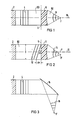
- an ultrasound transmitter for example a flat ultrasound wave field 4 falls on an acoustic lens 6 serving as an imaging device.
- the acoustic lens 6 converts the flat wave field 4 into a transmitted spherical wave field 8, the radius center of which under ideal imaging conditions coincides with the focal point F of the acoustic lens 6 on the image side lying on the lens axis 10.
- a plano-concave lens 6 is shown as the acoustic lens 6, for example, which acts as a converging lens if the speed of sound in the lens is greater than the speed of sound in a sound-carrying medium 50 surrounding the lens.
- the lens 6 is made, for example, of a Polymer, preferably polymethacrylic acid methyl ester PMMA or polystyrene PS and the medium 50 surrounding it consists, for example, of water.
- the spatial distribution of the sound pressure is homogeneous in an intersection 5 of the beam path of the plane wave field 4, which coincides, for example, with the plane surface of the plano-concave lens 6 and which is, for example, perpendicular to its direction of propagation and the measurement signals determined at different measurement locations in the cutting surface 5 are in phase.
- FIG. 2 shows the imaging relationships for the case in which, for example, a flat ultrasonic wave 12 strikes the acoustic lens 6, the wave normals of which are not parallel to the lens axis 10.
- a spherical acoustic wave field 14 is formed in the image space, the radius center of which is the image-side focus F 'of the ultrasonic wave 12 impinging on the acoustic lens 6.
- the image-side focus F ' lies outside the lens axis 10 and thus no longer coincides with the image-side focal point F of the acoustic lens 6.
- the measurement signals determined in the cutting surface 5 are no longer in phase, since the surfaces of the same phase are inclined by an angle ⁇ with respect to the cutting surface 5.
- the measurement signals ascertained in the sectional area 5 in the beam path of the plane wave field 12 are delayed with respect to one another.
- FIGS. 3 and 4 show the imaging ratios for two flat wave fields 4 and 12 striking a concave mirror 16. Corresponding to the direction of their respective wave normals, spherical wave fields 18 and 20 arise, the foci F 'and F ⁇ of which lie at different locations in the image space.
- the properties of the focus can be reconstructed from this, since then that between the sound pressure distribution in the specified sectional area and the properties of the focus are known mathematical relationships. This also applies if, in contrast to the examples explained with reference to FIGS. 1 to 5, the ultrasound waves incident on the acoustic imaging device are not flat and, for example, originate from a point-shaped ultrasound source. If, for example, the cut surface lies in an area in which the ultrasound wave incident on the imaging device 6 or 16, for example plane waves 4 or 12, is measured, the properties of the imaging device must be known when reconstructing the properties of the focus.
- the properties of the focus can no longer be exactly reconstructed.
- the measured values for the sound pressure amplitude determined at these locations can, however, be compared with the corresponding target values for which the position of the focus is known and thus allow the focus self to be checked create. If the measured values do not agree with the target values within predetermined limits, it can be concluded that the properties of the sound field and thus also the properties of the focus have changed in an impermissible manner.
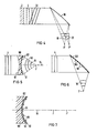
- an acoustic lens 60 is provided on one of its imaging surfaces 61 with a plurality of piezoelectric transducers 62 which can be arranged on it, for example in a matrix.
- the acoustic lens 60 is preferably made of a plastic, in particular polystyrene PS.
- the piezoelectric transducers 62 preferably consist of a piezoelectric polymer, for example polarized polyvinyl chloride PVC, in particular of polarized polyvinylidene fluoride PVDF, which is provided with thin metallic electrodes.
- acoustic impedance of the piezoelectric transducers 62 is largely matched to the acoustic impedance of the sound-carrying medium 50 and the acoustic impedance of the lens. This advantageously reduces those at the additional interfaces between lens 60 and ultrasonic transducer 62 and between ultrasonic transducer 62 and sound-carrying medium 50.
- a polymer film can be easily applied to the curved lens surface because of its high deformability.
- the reflecting surface 161 of a concave mirror 162 is provided with piezoelectric transducers 163.
- the piezoelectric transducers 163 consist of a piezoelectric polymer film provided with electrodes.
- a lens 80 is provided with a piezoelectric polymer film 90 on its surface 82 facing the image-side focal point F.
- the piezoelectric polymer film 90 is provided on its flat side facing the lens 80 with a coherent, electrically conductive, for example metallic, layer 92.
- the piezoelectric polymer film is provided with electrodes 94 and 96 on its flat side facing the focal point F on the image side.
- a plurality of annular outer electrodes 96 are arranged electrically separated from one another around a central electrode 94. Lead electrodes 98 lead from electrodes 96 and 94 to the edge of the film.
- the electrodes 94 and 96 have a shape which is rotationally symmetrical about the lens axis 84.
- the shape of the electrodes 94 and 96 is adapted to the radius of curvature of the surface 82.
- the center electrode 94 With a concave surface 82, the center electrode 94 has a spherical shape. If the surface 82 is flat, the center electrode 94 is designed in the form of a circular disk.
- the rotationally symmetrical arrangement of the electrodes 96 and 94 ensures that each electrode 96 and 94 intersects the spherical wave bundled in the image-side focal point F at locations of approximately the same phase .
- the radius of curvature of lens 80 is generally not the same as the radius of curvature of the spherical shaft at the location of lens surface 82.
- a relocation of the Image-side focus of the ultrasound wave can then be recognized in that the phase relationships between the individual signals that result when focussing in focus F are no longer fulfilled.
- a lateral shift of the image-side focus for example to point F 'on the lens axis 84, then results in a reduction in the phase difference between the electrical signals measured at the individual electrodes 94 and 96.
- the position of the focus F 'can then be calculated from the measured phase difference.
- a lens 64 is divided into two parts 66 and 68 by a single piezoelectric polymer film 70.
- the piezoelectric polymer film 70 is provided on one flat side with, for example, a matrix-shaped arrangement of electrodes 72, from which connecting conductors 74 lead to the edge of the film 70.
- a concave mirror 40 is provided with bores 42 which run perpendicular to its surface 41.
- Ultrasonic receivers 34 are inserted into the bores 42.
- the ultrasound receivers 34 are preferably made of a material with a high acoustic impedance, for example a piezoceramic material, in order to keep the transmission losses at the interface with the sound-carrying medium 50 as low as possible.
- a lens 30 is provided on the lens edge with bores 32 into which the ultrasound receivers 34 are inserted.
- Such a simplified embodiment is particularly suitable for simple control measurements in which only monitoring is carried out should, for example, whether the position of the focus still corresponds to the position determined by previous calibration.
- Such a device is less suitable for an accurate determination of the properties of the focus, since a change in the ultrasound field is determined only in the edge region of a cross-sectional area by the beam path. Since the ultrasound field is influenced by the ultrasound receiver 34 only in the edge region, piezoceramic ultrasound receivers 34 with high acoustic impedance can also be used.
Abstract
Erfindungsgemäß wird ein von einem Ultraschall-Sender (2) erzeugtes Ultraschallfeld (4, 12) in einer Schnittfläche (5) des Strahlenganges am Ort der Abbildungsvorrichtung (6) an mehreren Orten gemessen. Die an diesen Orten ermittelten Meßwerte werden mit vorgegebenen Sollwerten, für welche die Lage des Fokus bekannt ist, verglichen. In einer vorteilhaften Vorrichtung ist eine Oberfläche der Abbildungsvorrichtung (6) mit mehreren piezoelektrischen Wandlern versehen.According to the invention, an ultrasound field (4, 12) generated by an ultrasound transmitter (2) is measured in a sectional area (5) of the beam path at the location of the imaging device (6) at several locations. The measured values determined at these locations are compared with predetermined target values for which the position of the focus is known. In an advantageous device, a surface of the imaging device (6) is provided with a plurality of piezoelectric transducers.
Description
Die Erfindung bezieht sich auf ein Verfahren zur Kontrolle der Eigenschaften des Fokus eines fokussierten Ultraschallfeldes und eine Vorrichtung zur Durchführung des Verfahrens.The invention relates to a method for controlling the properties of the focus of a focused ultrasound field and a device for carrying out the method.
Fokussierte Ultraschallfelder werden beispielsweise in der Medizin eingesetzt, um im Körper befindliche Konkremente, wie z.B. Nierensteine, zu zerstören. Der Vorteil eines derartigen Verfahrens besteht darin, daß operative Eingriffe oder das Einführen von Sonden in den Körper des Patienten und die damit verbundene Gefährdung durch Infektionen vermieden werden.Focused ultrasound fields are used in medicine, for example, to remove concrements located in the body, e.g. To destroy kidney stones. The advantage of such a method is that surgical interventions or the insertion of probes into the patient's body and the associated risk from infections are avoided.
Aus der EP-A2 0 133 665 ist eine Einrichtung zum berührungslosen Zertrümmern eines Konkrements bekannt, bei dem die in einem Stoßwellenrohr erzeugte, annähernd ebene Ultraschallwelle mittels einer akustischen Linse oder eines akustischen Linsensystems auf das Zielgebiet fokussiert wird. Zwischen der Linse bzw. dem Linsensystem und einer als Ultraschall-Sender dienenden Kupfer-Membran befindet sich ein Koppelmedium. Durch eine Halterung kann das Stoßwellenrohr auf das Konkrement so ausgerichtet werden, daß der bildseitige Brennpunkt der Linse im Konkrement liegt. Die Linse kann außerdem zur genauen Justierung der Lage des Brennpunktes mit Hilfe einer Feinregulierung längs der Achse des Stoßwellenrohres verschoben werden.From EP-A2 0 133 665 a device for contactlessly crushing a concrement is known, in which the approximately flat ultrasonic wave generated in a shock wave tube is focused on the target area by means of an acoustic lens or an acoustic lens system. A coupling medium is located between the lens or the lens system and a copper membrane serving as an ultrasonic transmitter. The shock wave tube can be aligned with the concrement by means of a holder in such a way that the focal point of the lens on the image side lies in the concrement. The lens can also be used to precisely adjust the position of the focal point with the help of a fine adjustment lengthways the axis of the shock tube can be moved.
Ein Nachteil der genannten Einrichtung besteht nun darin, daß Veränderungen der Eigenschaften des Fokus, wie beispielsweise eine Veränderung seiner Lage oder eine Änderung seiner lateralen und axialen Ausdehnung, während der Anwendung der Einrichtung nicht erfaßt werden können. Zur Bestimmung der Eigenschaften des Fokus muß nämlich das Gerät vom Patienten entfernt und in einer geeigneten Vorrichtung überprüft werden. Solche Veränderungen der Eigenschaften des Fokus können beispielsweise durch eine Änderung des vom Ultraschall-Sender abgestrahlten Wellenfeldes oder durch eine mechanische Dejustierung des Abbildungssystems entstehen.A disadvantage of the device mentioned is that changes in the properties of the focus, such as a change in its position or a change in its lateral and axial extent, cannot be detected during use of the device. To determine the properties of the focus, the device must be removed from the patient and checked in a suitable device. Such changes in the properties of the focus can arise, for example, from a change in the wave field emitted by the ultrasound transmitter or from a mechanical misalignment of the imaging system.
Der Erfindung liegt nun die Aufgabe zugrunde, ein Verfahren anzugeben, das die Bestimmung der Eigenschaften des Fokus eines in einem Objekt fokussierten Ultraschallfeldes auch während der Beschallung des Objektes ermöglicht.The invention is based on the object of specifying a method which enables the properties of the focus of an ultrasound field focused in an object to be determined even during the sonication of the object.
Diese Aufgabe wird erfindungsgemäß gelöst mit den kennzeichnenden Merkmalen des Anspruchs 1. Die räumliche und zeitliche Schalldruckverteilung in einer Schnittfläche durch den Strahlengang ist bei Kenntnis der akustischen und geometrischen Eigenschaften der sich im weiteren Strahlengang befindenden Medien mit den Eigenschaften des Fokus, d.h. seiner Lage und seinen lateralen und axialen Abmessungen mathematisch verknüpft. Insbesondere kann diese Schnittfläche, die im allgemeinen auch gekrümmt sein kann, auch innerhalb oder auf den abbildenden Flächen der Abbildungsvorrichtung liegen. Je größer die zeitliche und räumliche Auflösung ist, mit der die Schalldruckverteilung in der Schnittfläche bekannt ist, desto genauer lassen sich die Eigenschaften des Fokus rekonstruieren. Zur Kontrolle der Lage des Fokus werden die an vorgegebenen Orten im Strahlengang ermittelten Meßwerte mit den bei einer Kalibriermessung ermittelten Sollwerten, für welche die Lage der Fokus bekannt ist, verglichen. Liegen die gemessenen Werte außerhalb eines tolerierbaren Sollwertbereiches, so ist dies ein Hinweis dafür, daß sich die Eigenschaften des Schallfeldes geändert haben und daß eine unzulässige Veränderung der Fokuslage eingetreten ist.This object is achieved according to the invention with the characterizing features of claim 1. The spatial and temporal distribution of sound pressure in a sectional area through the beam path is, with knowledge of the acoustic and geometric properties of the media located in the further beam path, with the properties of the focus, ie its position and its lateral and axial dimensions mathematically linked. In particular, this cut surface, which can generally also be curved, can also lie within or on the imaging surfaces of the imaging device. The greater the temporal and spatial resolution with which the sound pressure distribution in the cut surface is known, the more accurate the properties of the focus can be reconstructed. To check the position of the focus, the measured values determined at predetermined locations in the beam path are compared with the target values determined during a calibration measurement, for which the position of the focus is known. If the measured values lie outside a tolerable setpoint range, this is an indication that the properties of the sound field have changed and that an inadmissible change in the focus position has occurred.
Durch das genannte Verfahren wird somit eine Änderung der Eigenschaften des Fokus während der Beschallung des Objektes erkannt. Bei Anwendung des Verfahrens beispielsweise während des Betriebs eines Nierensteinzertrümmerers wird die Gefahr der Schädigung der das Konkrement umgebenen gesunden Niere verringert.A change in the properties of the focus is thus recognized by the aforementioned method during the sonication of the object. If the method is used, for example, during the operation of a kidney stone breaker, the risk of damage to the healthy kidney surrounding the calculus is reduced.
In einer geeigneten Vorrichtung zur Durchführung des Verfahrens werden in einer Schnittfläche des Strahlengangs Ultraschall-Empfänger angeordnet. Die Ultraschall-Empfänger bestehen vorzugsweise aus piezoelektrischen Polymerfolien, die mit metallischen Elektroden und Anschlußleitern versehen sind.In a suitable device for carrying out the method, ultrasound receivers are arranged in a cut surface of the beam path. The ultrasound receivers preferably consist of piezoelectric polymer films which are provided with metallic electrodes and connecting conductors.
Die aus piezoelektrischen Polymerfolien bestehenden Ultraschall-Empfänger sind in vorteilhafter Weise auf einer im Strahlengang der Ultraschallwelle befindlichen Oberfläche der Abbildungsvorrichtung angeordnet.The ultrasound receivers consisting of piezoelectric polymer films are advantageously arranged on a surface of the imaging device located in the beam path of the ultrasound wave.
Diese Ultraschall-Empfänger können entweder als einzelne voneinander räumlich getrennte Folien vorliegen oder durch eine zusammenhängende Polymerfolie gebildet werden, die beispielsweise mit einer matrixförmigen Elektrodenanordnung versehen ist, bei denen eine Elektrode jeweils mit einem Anschlußleiter verbunden ist.These ultrasound receivers can either be present as individual foils which are spatially separated from one another or can be formed by a coherent polymer foil which is provided, for example, with a matrix-shaped electrode arrangement, in which one electrode is connected to a connecting conductor.
In einer besonders vorteilhaften Ausführungsform ist auf der dem Fokus zugewandten Oberfläche der Abbildungsvorrichtung eine piezoelektrische Polymerfolie angeordnet, die mit wenigstens einer ringförmigen Außenelektrode und mit einer kreisscheibenförmigen Mitteleketrode versehen ist. Durch die rotationssymmetrische Gestalt der Empfängerfläche ist gewährleistet, daß wenigstens annähernd phasengleiche Bereiche des fokussierten Ultraschallfeldes von einem einzigen Empfangselement erfaßt werden und die Anzahl der auszulesenden Empfangselemente ist bei vorgegebener Gesamtempfangsfläche verringert.In a particularly advantageous embodiment, a piezoelectric polymer film is arranged on the surface of the imaging device facing the focus, which is provided with at least one ring-shaped outer electrode and with a circular disk-shaped center electrode. The rotationally symmetrical shape of the receiver surface ensures that at least approximately in-phase areas of the focused ultrasound field are detected by a single receiving element and the number of receiving elements to be read out is reduced for a given total receiving surface.
In einer weiteren vorteilhaften Anordnung wird eine akustische Linse durch eine piezoelektrische Polymerfolie, die ebenfalls mit einer matrixförmigen Elektrodenanordnung versehen ist, in zwei Teile getrennt.In a further advantageous arrangement, an acoustic lens is separated into two parts by a piezoelectric polymer film, which is also provided with a matrix-shaped electrode arrangement.
In einer vereinfachten Ausführungsform wird das Schallfeld am Ort der Abbildungsvorrichtung nur an wenigen vorgegebenen Punkten überwacht wird. Dazu werden in einer vorteilhaften Anordnung die Elemente der Abbildungsvorrichtung mit Bohrungen versehen, in die die Ultraschall-Empfänger eingesetzt werden. Bringt man bei Verwendung einer Linse die Bohrungen im Randbereich der Linse unter, so können auch piezokeramische Ultraschall-Empfänger verwendet werden.In a simplified embodiment, the sound field at the location of the imaging device is only monitored at a few predetermined points. For this purpose, in an advantageous arrangement, the elements of the imaging device are provided with bores into which the ultrasound receivers are inserted. If the holes are placed in the edge area of the lens when using a lens, piezoceramic ultrasound receivers can also be used.
Zur weiteren Erläuterung der Erfindung wird auf die Zeichnung Bezug genommen, in deren
Figuren 1, 2, 3 und 4 das Prinzip des Verfahrens gemäß der Erfindung erläutert ist.Figuren 5 und 6 zeigen jeweils vorteilhafte Anordnungen zur Durchführung des Verfahrens im Schnitt.- Figuren 7 und 8 zeigen eine Anordnung im Schnitt bzw. in einer Draufsicht, bei der die dem Fokus zugewandte Oberfläche der Abbildungsvorrichtung mit ringförmigen Ultraschall-Empfängern versehen ist. In
- Figuren 9 und 10 ist eine besonders vorteilhafte Gestaltung einer akustischen Linse mit einer Ultraschall-Empfangsmatrix im Schnitt bzw. in einer Draufsicht dargestellt. Gemäß
- Figuren 11 und 12 sind Ultraschall-Empfänger in ein mit Bohrungen versehenes abbildendes Element eingesetzt.
- Figures 1, 2, 3 and 4 the principle of the method according to the invention is explained.
- Figures 5 and 6 each show advantageous arrangements for performing the method in section.
- FIGS. 7 and 8 show an arrangement in section or in a top view, in which the surface of the imaging device facing the focus is provided with ring-shaped ultrasound receivers. In
- FIGS. 9 and 10 show a particularly advantageous design of an acoustic lens with an ultrasound reception matrix in section or in a top view. According to
- 11 and 12, ultrasound receivers are inserted into an imaging element provided with bores.
Gemäß Figur 1 fällt ein von einem Ultraschall-Sender 2 erzeugtes, beispielsweise ebenes Ultraschall-Wellenfeld 4 auf eine als Abbildungsvorrichtung dienende akustische Linse 6. Die akustische Linse 6 wandelt das ebene Wellenfeld 4 in ein transmittiertes kugelförmiges Wellenfeld 8 um, dessen Radiusmittelpunkt bei idealen Abbildungsbedingungen mit dem auf der Linsenachse 10 liegenden bildseitigen Brennpunkt F der akustischen Linse 6 zusammenfällt. Als akustische Linse 6 ist beispielsweise eine plankonkave Linse 6 dargestellt, die dann als Sammellinse wirkt, wenn die Schallgeschwindigkeit in der Linse größer ist als die Schallgeschwindigkeit in einem die Linse umgebenden schalltragenden Medium 50. Dies ist der Fall, wenn die Linse 6 beispielsweise aus einem Polymer, vorzugsweise Polymethacrylsäuremethylester PMMA oder Polystyrol PS und das sie umgebende Medium 50 beispielsweise aus Wasser besteht. In einer Schnittfläche 5 des Strahlengangs des ebenen Wellenfeldes 4, die beispielsweise mit der ebenen Fläche der plankonkaven Linse 6 zusammenfällt und die beispielsweise senkrecht zu dessen Ausbreitungsrichtung liegt, ist die räumliche Verteilung des Schalldruckes homogen und die an verschiedenen Meßorten in der Schnittfläche 5 ermittelten Meßsignale sind phasengleich.According to FIG. 1, an
In Figur 2 sind die Abbildungsverhältnisse für den Fall dargestellt, in dem eine beispielsweise ebene Ultraschallwelle 12 auf die akustische Linse 6 fällt, deren Wellennormalen nicht parallel zur Linsenachse 10 sind. Im Bildraum entsteht ein kugelförmiges akustisches Wellenfeld 14, dessen Radiusmittelpunkt der bildseitige Fokus F′ der auf die akustische Linse 6 auftreffenden Ultraschallwelle 12 ist. Der bildseitige Fokus F′ liegt außerhalb der Linsenachse 10 und fällt somit nicht mehr mit dem bildseitigen Brennpunkt F der akustischen Linse 6 zusammen. Die in der Schnittfläche 5 ermittelten Meßsignale sind nicht mehr phasengleich, da die Flächen gleicher Phase gegen die Schnittfläche 5 um einen Winkel α geneigt sind. Die in der Schnittfläche 5 im Strahlengang des ebenen Wellenfeldes 12 ermittelten Meßsignale sind gegeneinander zeitlich verzögert. Die maximale zeitliche Verzögerung Δtmax zwischen zwei Meßsignalen beträgt dann Δx/c, wobei c die Schallgeschwindigkeit im schalltragenden Medium 50 ist und Δx sich aus der Apertur D des ebenen Wellenfeldes 12 durch die Beziehung Δx = D . tanα ergibt. Wird eine derartige zeitliche Verzögerung der an verschiedenen Orten innerhalb der Schnittfläche 5 ermittelten Meßsignale festgestellt, dann kann daraus gefolgert werden, daß der beidseitige Fokus F′ mit dem bildseitigen Brennpunkt nicht mehr zusammenfällt. Im Beispiel gemäß Figur 2 kann bei gegebenen Linseneigenschaften der bildseitige Fokus F′ aus der maximalen zeitlichen Verzögerung Δtmax ermittelt werden.FIG. 2 shows the imaging relationships for the case in which, for example, a flat
Zur Fokussierung eines Ultraschallfeldes kann auch ein beispielsweise metallischer Hohlspiegel verwendet wer den. In Figuren 3 und 4 sind die Abbildungsverhältnisse für zwei auf einen Hohlspiegel 16 auftreffende ebene Wellenfelder 4 und 12 dargestellt. Entsprechend der Richtung ihrer jeweiligen Wellennormalen entstehen kugelförmige Wellenfelder 18 bzw. 20, deren Foki F′ bzw. F˝ an verschiedenen Orten im Bildraum liegen.A metal concave mirror, for example, can also be used to focus an ultrasound field the. FIGS. 3 and 4 show the imaging ratios for two
Sind die räumliche und zeitliche Schalldruckverteilung in einer Schnittfläche des Strahlenganges und die geometrischen und akustischen Eigenschaften des im Gebiet zwischen dieser Schnittfläche und dem Fokus befindlichen Mediums bekannt, so können daraus die Eigenschaften des Fokus rekonstruiert werden, da dann die zwischen der Schalldruckverteilung in der vorgegebenen Schnittfläche und den Eigenschaften des Fokus bestehenden mathematischen Beziehungen bekannt sind. Dies gilt auch dann, wenn die auf die akustische Abbildungsvorrichtung einfallenden Ultraschallwellen im Gegensatz zu den anhand der Figuren 1 bis 5 erläuterten Beispielen nicht eben sind und beispielsweise von einer punktförmigen Ultraschallquelle ausgehen. Liegt beispielsweise die Schnittfläche in einem Gebiet, in dem die auf die Abbildungsvorrichtung 6 bzw. 16 einfallende Ultraschallwelle, beispielsweise ebene Wellen 4 oder 12, gemessen wird, so müssen bei der Rekonstruktion der Eigenschaften des Fokus die Eigenschaften der Abbildungsvorrichtung bekannt sein.If the spatial and temporal sound pressure distribution in a sectional area of the beam path and the geometric and acoustic properties of the medium located in the area between this sectional area and the focus are known, the properties of the focus can be reconstructed from this, since then that between the sound pressure distribution in the specified sectional area and the properties of the focus are known mathematical relationships. This also applies if, in contrast to the examples explained with reference to FIGS. 1 to 5, the ultrasound waves incident on the acoustic imaging device are not flat and, for example, originate from a point-shaped ultrasound source. If, for example, the cut surface lies in an area in which the ultrasound wave incident on the
Wird nur an wenigen vorgegebenen Orten in der Schnittfläche der zeitliche Verlauf des Schalldruckes gemessen, so lassen sich die Eigenschaften des Fokus nicht mehr exakt rekonstruieren. Die an diesen Orten ermittelten Meßwerte für die Schalldruckamplitude können jedoch mit den entsprechenden Sollwerten, für die die Lage des Fokus bekannt ist, verglichen werden und erlauben somit eine Kontrolle der Fokuseigen schaften. Stimmen die Meßwerte mit den Sollwerten innerhalb vorgegebener Grenzen nicht überein, so kann daraus gefolgert werden, daß sich die Eigenschaften des Schallfeldes und somit auch die Eigenschaften des Fokus in unzulässiger Weise verändert haben.If the temporal course of the sound pressure is only measured at a few predetermined locations in the cut surface, the properties of the focus can no longer be exactly reconstructed. The measured values for the sound pressure amplitude determined at these locations can, however, be compared with the corresponding target values for which the position of the focus is known and thus allow the focus self to be checked create. If the measured values do not agree with the target values within predetermined limits, it can be concluded that the properties of the sound field and thus also the properties of the focus have changed in an impermissible manner.
Gemäß Figur 5 ist eine akustische Linse 60 auf einer ihrer abbildenden Oberflächen 61 mit mehreren piezoelektrischen Wandlern 62 versehen die beispielsweise matrixförmig auf ihr angeordnet sein können. Die akustische Linse 60 besteht vorzugsweise aus einem Kunststoff, insbesondere aus Polystyrol PS. Die piezoelektrischen Wandler 62 bestehen vorzugsweise aus einem piezoelektrischen Polymer beispielsweise polarisiertem Polyvinylchlorid PVC, insbesondere aus polarisiertem Polyvinylidenfluorid PVDF, das mit dünnen metallischen Elektroden versehen ist. Dies hat den Vorteil, daß die akustische Impedanz der piezoelektrischen Wandler 62 der akustischen Impedanz des schalltragenden Mediums 50 und der akustischen Impedanz der Linse weitgehend angepaßt ist. Dadurch werden die an den zusätzlichen Grenzflächen zwischen Linse 60 und Ultraschallwandler 62 sowie zwischen Ultraschallwandler 62 und schalltragendem Medium 50 in vorteilhafter Weise verringert. Außerdem kann eine Polymerfolie wegen ihrer hohen Verformbarkeit auf die gekrümmte Linsenoberfläche leicht aufgebracht werden.According to FIG. 5, an
Bei der in Figur 6 dargestellten Vorrichtung ist die reflektierende Oberfläche 161 eines Hohlspiegels 162 mit piezoelektrischen Wandlern 163 versehen. Auch in diesem Fall ist es wegen der gekrümmten Oberfläche 161 des Hohlspiegels 162 von Vorteil, wenn die piezoelektrischen Wandler 163 aus einer mit Elektroden versehenen piezoelektrischenn Polymerfolie bestehen.In the device shown in FIG. 6, the reflecting
Gemäß Figur 7 ist eine Linse 80 an ihrer dem bildseitigen Brennpunkt F zugewandten Oberfläche 82 mit einer piezoelektrischen Polymerfolie 90 versehen. Die piezoelektrische Polymerfolie 90 ist an ihrer der Linse 80 zugewandten Flachseite mit einer zusammenhängenden elektrisch leitfähigen, beispielsweise metallischen Schicht 92 versehen. Auf ihrer dem bildseitigen Brennpunkt F zugewandten Flachseite ist die piezoelektrische Polymerfolie mit Elektroden 94 und 96 versehen. Entsprechend Figur 8 sind mehrere ringförmige Außenelektroden 96 um eine Mittelelektrode 94 voneinander elektrisch getrennt angeordnet. Von den Elektroden 96 und 94 führen Anschlußleiter 98 bis zum Rand der Folie. Die Elektroden 94 und 96 haben bis auf den von den Anschlußleitern 98 gebildeten Bereich eine um die Linsenachse 84 rotationssymmetrische Gestalt. Die Elektroden 94 und 96 sind in ihrer Form dem Krümmungsradius der Oberfläche 82 angepaßt. Bei einer konkaven Oberfläche 82 hat die Mittelelektrode 94 eine kalottenförmige Gestalt. Ist die Oberfläche 82 plan, so ist die Mittelelektrode 94 in Form einer Kreisscheibe ausgebildet. Wenn der Durchmesser der Mittelelektrode 94 und die Breite der Außenelektroden 96 ausreichend klein gewählt werden, so ist wegen der rotationssymmetrischen Anordnung der Elektroden 96 und 94 gewährleistet, daß jede Elektrode 96 bzw. 94 die im bildseitigen Brennpunkt F gebündelte Kugelwelle an Orten annähernd gleicher Phase schneidet. Zwischen den an den einzelnen Elektroden entstehenden Meßsignalen besteht dann in diesem Fall eine feste Phasendifferenz, die sich aus den unterschiedlichen Laufstrecken der kugelförmigen Ultraschallwelle zum bildseitigen Brennpunkt F und der Schallgeschwindigkeit ergibt. Dabei ist zu beachten, daß der Krümmungsradius der Linse 80 im allgemeinen nicht mit dem Krümmungsradius der Kugelwelle am Ort der Linsenoberfläche 82 identisch ist. Eine Verlagerung des bildseitigen Fokus der Ultraschallwelle kann dann dadurch erkannt werden, daß die bei Fokussierung im Brennpunkt F sich ergebenden Phasenbeziehungen zwischen den einzelnen Signalen nicht mehr erfüllt sind. Eine laterale Verschiebung des bildseitigen Fokus beispielsweise zum Punkt F′ auf der Linsenachse 84 macht sich dann in einer Verringerung der Phasendifferenz zwischen den an den einzelnen Elektroden 94 und 96 gemessenen elektrischen Signalen. In diesem Fall kann dann aus der gemessenen Phasendifferenz die Lage des Fokus F′ errechnet werden.According to FIG. 7, a
In Figur 9 wird eine Linse 64 durch eine einzige piezoelektrische Polymerfolie 70 in zwei Teile 66 und 68 aufgeteilt. Gemäß Figur 10 ist die piezoelektrische Polymerfolie 70 auf einer Flachseite mit einer beispielsweise matrixförmigen Anordnung von Elektroden 72 versehen, von denen Anschlußleiter 74 zum Rand der Folie 70 führen.In FIG. 9, a
In Figur 11 ist ein Hohlspiegel 40 mit Bohrungen 42 versehen, die senkrecht zu seiner Oberfläche 41 verlaufen. In die Bohrungen 42 sind Ultraschall-Empfänger 34 eingesetzt. Die Ultraschall-Empfänger 34 bestehen vorzugsweise aus einem Material mit hoher akustischer Impedanz, beispielsweise aus einem piezokeramischen Werkstoff, um die Transmissionsverluste an der Grenzfläche zum schalltragenden Medium 50 möglichst gering zu halten.In FIG. 11, a concave mirror 40 is provided with bores 42 which run perpendicular to its surface 41.
Entsprechend Figur 12 ist eine Linse 30 am Linsenrand mit Bohrungen 32 versehen, in die die Ultraschall-Empfänger 34 eingesetzt werden. Eine derartige vereinfachte Ausführungsform ist besonders für einfache Kontrollmessungen geeignet, bei denen nur überwacht werden soll, ob beispielsweise die Lage des Fokus mit der durch vorhergehende Kalibrierung ermittelten Lage noch übereinstimmt. Für eine genaue Bestimmung der Eigenschaften des Fokus ist eine derartige Vorrichtung weniger geeignet, da eine Veränderung des Ultraschallfeldes nur im Randbereich einer Querschnittsfläche durch den Strahlengang festgestellt wird. Da eine Beeinflussung des Ultraschallfeldes durch den Ultraschallempfänger 34 nur im Randbereich erfolgt, können auch piezokeramische Ultraschall-Empfänger 34 mit hoher akustischer Impedanz verwendet werden.According to FIG. 12, a
Claims (7)
- das Ultraschallfeld wird in einer Schnittfläche des Strahlenganges an mehreren Orten gemessen,
- die Schnittfläche befindet sich an einer abbildenden Oberfläche oder innerhalb der Abbildungsvorrichtung (6).
- die Meßwerte werden mit vorgegebenen Sollwerten verglichen.1. A method for controlling the characteristics of the focus of a focused ultrasonic field, characterized by the following features:
the ultrasound field is measured in a sectional area of the beam path at several locations,
- The cut surface is on an imaging surface or within the imaging device (6).
- The measured values are compared with specified target values.
- wenigstens ein Element der Abbildungsvorrichtung ist mit piezoelektrischen Wandlern versehen,
- als piezoelektrische Wandler sind piezoelektrische Polymerfolien vorgesehen.2. Device for performing the method according to claim 1, characterized by the following features:
at least one element of the imaging device is provided with piezoelectric transducers,
- Piezoelectric polymer films are provided as piezoelectric transducers.
- in der Querschnittsfläche des Strahlenganges ist eine einzige piezoelektrische Polymerfolie (70) angeordnet
- die piezoelektrische Polymerfolie (70) ist mit einer matrixförmigen Anordnung von Elektroden (72) versehen
- einer der Elektroden (72) ist jeweils ein Anschluß leiter (74) zugeordnet, der zum Rand der Polymerfolie (70) führt.4. Apparatus according to claim 2 or 3, characterized by the following features:
- In the cross-sectional area of the beam path, a single piezoelectric polymer film (70) is arranged
- The piezoelectric polymer film (70) is provided with a matrix-shaped arrangement of electrodes (72)
- One of the electrodes (72) is a connection assigned conductor (74), which leads to the edge of the polymer film (70).
- als Abbildungsvorrichtung ist eine akustische Linse ( (64) vorgesehen,
- die akustische Linse (64) wird durch die piezoelektrische Polymerfolie (70) in zwei Teile (66 und 68) getrennt.5. Device according to claim 4, characterized by the following features:
- an acoustic lens ((64) is provided as the imaging device,
- The acoustic lens (64) is separated by the piezoelectric polymer film (70) in two parts (66 and 68).
- als Abbildungsvorrichtung ist eine akustische Linse (80) vorgesehen,
- auf der dem Brennpunkt F zugewandten Oberfläche (82) ist eine piezoelektrische Polymerfolie (90) angeordnet,
- die piezoelektrische Polymerfolie (90) ist mit einer der Krümmung der Oberfläche (82) der Linse (80) angepaßten Mittelelektrode (96) und mit konzentrisch um die Mittelelektrode (94) angeordneten ringförmigen Außenelektroden (96) versehen,
- die Elektroden (94, 96) sind jeweils mit Anschlußleitern (98) versehen, die zum Rand der Polymerfolie (90) führen,
- die Elektroden (94, 96) sind mit Ausnahme des von den Anschlußleitern (98) gebildeten Bereiches rotationssymmetrisch um die Linsenachse (84) angeordnet.6. Apparatus according to claim 3, characterized by the following features:
an acoustic lens (80) is provided as the imaging device,
a piezoelectric polymer film (90) is arranged on the surface (82) facing the focal point F,
the piezoelectric polymer film (90) is provided with a central electrode (96) adapted to the curvature of the surface (82) of the lens (80) and with annular outer electrodes (96) arranged concentrically around the central electrode (94),
- The electrodes (94, 96) are each provided with connecting conductors (98) which lead to the edge of the polymer film (90),
- The electrodes (94, 96) are arranged with the exception of the area formed by the connecting conductors (98) in a rotationally symmetrical manner about the lens axis (84).
- wenigstens ein Element (30, 40) der Abbildungsvorrichtung ist an vorbestimmten Stellen mit Bohrungen (32 bzw. 42) versehen,
- in den Bohrungen (32 bzw. 42) sind Ultraschall-Empfänger (34) angeordnet.7. Device for carrying out the method according to claim 1, characterized by the following features:
- At least one element (30, 40) of the imaging device is at predetermined locations with bores (32 or 42),
- Ultrasonic receivers (34) are arranged in the bores (32 or 42).
Applications Claiming Priority (2)
| Application Number | Priority Date | Filing Date | Title |
|---|---|---|---|
| DE3545352 | 1985-12-20 | ||
| DE3545352 | 1985-12-20 |
Publications (2)
| Publication Number | Publication Date |
|---|---|
| EP0229981A1 true EP0229981A1 (en) | 1987-07-29 |
| EP0229981B1 EP0229981B1 (en) | 1990-02-28 |
Family
ID=6289121
Family Applications (1)
| Application Number | Title | Priority Date | Filing Date |
|---|---|---|---|
| EP86117248A Expired - Lifetime EP0229981B1 (en) | 1985-12-20 | 1986-12-11 | Method for controlling the focussing characteristics of an ultrasonic field and device for carrying out said method |
Country Status (4)
| Country | Link |
|---|---|
| US (1) | US4725989A (en) |
| EP (1) | EP0229981B1 (en) |
| JP (1) | JPS62152300A (en) |
| DE (1) | DE3669203D1 (en) |
Cited By (2)
| Publication number | Priority date | Publication date | Assignee | Title |
|---|---|---|---|---|
| EP0362529A1 (en) * | 1988-10-05 | 1990-04-11 | Dornier Medizintechnik Gmbh | Combined shock wave generator |
| DE4034533C1 (en) * | 1990-10-30 | 1992-01-30 | Siemens Ag, 8000 Muenchen, De |
Families Citing this family (11)
| Publication number | Priority date | Publication date | Assignee | Title |
|---|---|---|---|---|
| DE3545381C2 (en) * | 1985-12-20 | 1994-02-24 | Siemens Ag | Ultrasonic transducer for measuring the sound power of a focused ultrasonic field |
| DE3732131A1 (en) * | 1987-09-24 | 1989-04-06 | Wolf Gmbh Richard | FOCUSING ULTRASONIC transducer |
| JP2745147B2 (en) * | 1989-03-27 | 1998-04-28 | 三菱マテリアル 株式会社 | Piezoelectric transducer |
| DE4102551A1 (en) * | 1991-01-29 | 1992-07-02 | Wolf Gmbh Richard | METHOD FOR DETERMINING THE ACOUSTIC PERFORMANCE OF FOCUSING ELECTRO-ACOUSTIC TRANSDUCERS AND DEVICE FOR IMPLEMENTING THE METHOD |
| DE4213586C2 (en) * | 1992-04-24 | 1995-01-19 | Siemens Ag | Therapy device for treatment with focused acoustic waves |
| DE102004043180B3 (en) * | 2004-09-01 | 2006-05-24 | Fraunhofer-Gesellschaft zur Förderung der angewandten Forschung e.V. | Device for nondestructive testing of components by means of ultrasonic waves |
| US20090178465A1 (en) * | 2008-01-14 | 2009-07-16 | Ethridge Roger E | Acoustic transducer support frame and method |
| US7578166B2 (en) * | 2008-01-14 | 2009-08-25 | Grant Prideco, L.P. | Acoustic transducer calibration block and method |
| US7770689B1 (en) * | 2009-04-24 | 2010-08-10 | Bacoustics, Llc | Lens for concentrating low frequency ultrasonic energy |
| JP2015219540A (en) * | 2014-05-14 | 2015-12-07 | 株式会社デンソー | Tactile display device |
| US11109909B1 (en) * | 2017-06-26 | 2021-09-07 | Andreas Hadjicostis | Image guided intravascular therapy catheter utilizing a thin ablation electrode |
Citations (3)
| Publication number | Priority date | Publication date | Assignee | Title |
|---|---|---|---|---|
| DE3220751A1 (en) * | 1982-06-02 | 1983-12-08 | Jörg Dr. 8022 Grünwald Schüller | Device for crushing concrements, especially renal calculi, in living human or animal bodies |
| EP0133665A2 (en) * | 1983-08-03 | 1985-03-06 | Siemens Aktiengesellschaft | Apparatus for the smashing at a distance of calculus |
| EP0133946A2 (en) * | 1983-08-03 | 1985-03-13 | Siemens Aktiengesellschaft | Apparatus for the contactless disintegration of concrements |
Family Cites Families (7)
| Publication number | Priority date | Publication date | Assignee | Title |
|---|---|---|---|---|
| JPS5711648A (en) * | 1980-06-27 | 1982-01-21 | Matsushita Electric Ind Co Ltd | Ultrasonic probe |
| US4387599A (en) * | 1981-01-06 | 1983-06-14 | Arthur Samodovitz | Multiple field acoustic focusser |
| FR2499348A1 (en) * | 1981-02-02 | 1982-08-06 | Labo Electronique Physique | DEVICE FOR CALIBRATING ULTRASONIC TRANSDUCERS |
| JPS58122456A (en) * | 1982-01-14 | 1983-07-21 | Hitachi Ltd | Ultrasonic microscope |
| US4476549A (en) * | 1982-03-31 | 1984-10-09 | The United States Of America As Represented By The Secretary Of The Navy | Calibration method for acoustic scattering measurements using a spherical target |
| US4475376A (en) * | 1982-12-01 | 1984-10-09 | Advanced Technology Laboratories, Inc. | Apparatus for testing ultrasonic transducers |
| US4576034A (en) * | 1984-02-27 | 1986-03-18 | Westinghouse Electric Corp. | Adjustable radius apparatus for calibrating ultrasonic transducer array |
-
1986
- 1986-12-11 EP EP86117248A patent/EP0229981B1/en not_active Expired - Lifetime
- 1986-12-11 DE DE8686117248T patent/DE3669203D1/en not_active Expired - Fee Related
- 1986-12-12 US US06/940,844 patent/US4725989A/en not_active Expired - Fee Related
- 1986-12-19 JP JP61305144A patent/JPS62152300A/en active Pending
Patent Citations (3)
| Publication number | Priority date | Publication date | Assignee | Title |
|---|---|---|---|---|
| DE3220751A1 (en) * | 1982-06-02 | 1983-12-08 | Jörg Dr. 8022 Grünwald Schüller | Device for crushing concrements, especially renal calculi, in living human or animal bodies |
| EP0133665A2 (en) * | 1983-08-03 | 1985-03-06 | Siemens Aktiengesellschaft | Apparatus for the smashing at a distance of calculus |
| EP0133946A2 (en) * | 1983-08-03 | 1985-03-13 | Siemens Aktiengesellschaft | Apparatus for the contactless disintegration of concrements |
Cited By (2)
| Publication number | Priority date | Publication date | Assignee | Title |
|---|---|---|---|---|
| EP0362529A1 (en) * | 1988-10-05 | 1990-04-11 | Dornier Medizintechnik Gmbh | Combined shock wave generator |
| DE4034533C1 (en) * | 1990-10-30 | 1992-01-30 | Siemens Ag, 8000 Muenchen, De |
Also Published As
| Publication number | Publication date |
|---|---|
| DE3669203D1 (en) | 1990-04-05 |
| US4725989A (en) | 1988-02-16 |
| EP0229981B1 (en) | 1990-02-28 |
| JPS62152300A (en) | 1987-07-07 |
Similar Documents
| Publication | Publication Date | Title |
|---|---|---|
| EP0229981B1 (en) | Method for controlling the focussing characteristics of an ultrasonic field and device for carrying out said method | |
| DE4241161C2 (en) | Acoustic therapy facility | |
| EP0327917B1 (en) | Shock wave generator for the non-contacting disintegration of concretions in a body | |
| DE3545381C2 (en) | Ultrasonic transducer for measuring the sound power of a focused ultrasonic field | |
| EP0268818B1 (en) | Equipment for the transmission and reception of ultrasonic signals | |
| DE4405504B4 (en) | Method and apparatus for imaging an object with a 2-D ultrasound array | |
| EP0300315B1 (en) | Shock wave generator for an apparatus for non-contact disintegration of concrements, present in a body | |
| DE10248741A1 (en) | Ultrasonic imaging device for medical applications, has acoustic lens comprising inner and outer cylindrical portions which have different acoustic refractive index and different attenuation characteristics | |
| DE69936507T2 (en) | CATHETER WITH RINGELY MOUNTED ULTRASOUND TRANSFORMERS | |
| US5706820A (en) | Ultrasonic transducer with reduced elevation sidelobes and method for the manufacture thereof | |
| DE4008768A1 (en) | PIEZOELECTRIC CONVERTER | |
| DE2308443A1 (en) | EXAMINATION DEVICE WITH CATHETER FOR EXAMINING A HOLLOW ORGAN WITH THE AID OF ULTRASOUND WAVES AND METHOD OF MAKING THE CATHETER | |
| DE3526488A1 (en) | ULTRASONIC CONVERTER WITH PIEZOELECTRIC COMPOSITE MATERIAL | |
| DE3328068A1 (en) | DEVICE FOR CONTACTLESS CRUSHING OF CONCRETE | |
| DE3320935A1 (en) | ULTRASONIC SENSOR | |
| DE3328039C2 (en) | FACILITIES FOR THE CONTACTLESS SMASHING OF A CONCERMENT IN THE BODY OF A LIVING BEING | |
| DE10197068T5 (en) | Multidimensional field and its production | |
| DD248067A5 (en) | GENERATOR WITH ELASTIC STRAITS OF LARGE STAERKS WHICH HAVE LIVING POINTS IN A LIQUID AND THROUGH COLLABORATIONS | |
| DE3732410A1 (en) | ULTRASONIC TRANSFORMER WITH ASTIGMATIC TRANSMITTER / RECEIVING CHARACTERISTICS | |
| DE4034533C1 (en) | ||
| DE60035995T2 (en) | FOCUSED ULTRASONIC TRANSDUCERS AND SYSTEMS | |
| DE4236255C2 (en) | Acoustic lens | |
| EP0210358B1 (en) | Acoustic focussing device | |
| EP0381796A1 (en) | Ultrasonic sensor | |
| EP1358476B1 (en) | Ultrasonic sensor for controlling the process during resistance spot welding |
Legal Events
| Date | Code | Title | Description |
|---|---|---|---|
| PUAI | Public reference made under article 153(3) epc to a published international application that has entered the european phase |
Free format text: ORIGINAL CODE: 0009012 |
|
| AK | Designated contracting states |
Kind code of ref document: A1 Designated state(s): DE FR GB NL |
|
| 17P | Request for examination filed |
Effective date: 19870925 |
|
| 17Q | First examination report despatched |
Effective date: 19880722 |
|
| GRAA | (expected) grant |
Free format text: ORIGINAL CODE: 0009210 |
|
| AK | Designated contracting states |
Kind code of ref document: B1 Designated state(s): DE FR GB NL |
|
| GBT | Gb: translation of ep patent filed (gb section 77(6)(a)/1977) | ||
| REF | Corresponds to: |
Ref document number: 3669203 Country of ref document: DE Date of ref document: 19900405 |
|
| ET | Fr: translation filed | ||
| PLBE | No opposition filed within time limit |
Free format text: ORIGINAL CODE: 0009261 |
|
| STAA | Information on the status of an ep patent application or granted ep patent |
Free format text: STATUS: NO OPPOSITION FILED WITHIN TIME LIMIT |
|
| 26N | No opposition filed | ||
| PGFP | Annual fee paid to national office [announced via postgrant information from national office to epo] |
Ref country code: GB Payment date: 19931122 Year of fee payment: 8 |
|
| PGFP | Annual fee paid to national office [announced via postgrant information from national office to epo] |
Ref country code: FR Payment date: 19931223 Year of fee payment: 8 |
|
| PGFP | Annual fee paid to national office [announced via postgrant information from national office to epo] |
Ref country code: NL Payment date: 19931231 Year of fee payment: 8 |
|
| PGFP | Annual fee paid to national office [announced via postgrant information from national office to epo] |
Ref country code: DE Payment date: 19940216 Year of fee payment: 8 |
|
| PG25 | Lapsed in a contracting state [announced via postgrant information from national office to epo] |
Ref country code: GB Effective date: 19941211 |
|
| PG25 | Lapsed in a contracting state [announced via postgrant information from national office to epo] |
Ref country code: NL Effective date: 19950701 |
|
| GBPC | Gb: european patent ceased through non-payment of renewal fee |
Effective date: 19941211 |
|
| PG25 | Lapsed in a contracting state [announced via postgrant information from national office to epo] |
Ref country code: FR Effective date: 19950831 |
|
| NLV4 | Nl: lapsed or anulled due to non-payment of the annual fee |
Effective date: 19950701 |
|
| PG25 | Lapsed in a contracting state [announced via postgrant information from national office to epo] |
Ref country code: DE Effective date: 19950901 |
|
| REG | Reference to a national code |
Ref country code: FR Ref legal event code: ST |