EP0385347A2 - Synchrones Steuerungssystem und Verfahren dafür - Google Patents
Synchrones Steuerungssystem und Verfahren dafür Download PDFInfo
- Publication number
- EP0385347A2 EP0385347A2 EP90103700A EP90103700A EP0385347A2 EP 0385347 A2 EP0385347 A2 EP 0385347A2 EP 90103700 A EP90103700 A EP 90103700A EP 90103700 A EP90103700 A EP 90103700A EP 0385347 A2 EP0385347 A2 EP 0385347A2
- Authority
- EP
- European Patent Office
- Prior art keywords
- spindle
- slave
- master
- rotation
- current position
- Prior art date
- Legal status (The legal status is an assumption and is not a legal conclusion. Google has not performed a legal analysis and makes no representation as to the accuracy of the status listed.)
- Ceased
Links
Images


Classifications
-
- G—PHYSICS
- G05—CONTROLLING; REGULATING
- G05B—CONTROL OR REGULATING SYSTEMS IN GENERAL; FUNCTIONAL ELEMENTS OF SUCH SYSTEMS; MONITORING OR TESTING ARRANGEMENTS FOR SUCH SYSTEMS OR ELEMENTS
- G05B19/00—Programme-control systems
- G05B19/02—Programme-control systems electric
- G05B19/18—Numerical control [NC], i.e. automatically operating machines, in particular machine tools, e.g. in a manufacturing environment, so as to execute positioning, movement or co-ordinated operations by means of programme data in numerical form
- G05B19/416—Numerical control [NC], i.e. automatically operating machines, in particular machine tools, e.g. in a manufacturing environment, so as to execute positioning, movement or co-ordinated operations by means of programme data in numerical form characterised by control of velocity, acceleration or deceleration
-
- G—PHYSICS
- G05—CONTROLLING; REGULATING
- G05B—CONTROL OR REGULATING SYSTEMS IN GENERAL; FUNCTIONAL ELEMENTS OF SUCH SYSTEMS; MONITORING OR TESTING ARRANGEMENTS FOR SUCH SYSTEMS OR ELEMENTS
- G05B2219/00—Program-control systems
- G05B2219/30—Nc systems
- G05B2219/50—Machine tool, machine tool null till machine tool work handling
- G05B2219/50234—Synchronize two spindles, axis, electronic transmission, line shafting
Definitions
- This invention relates to a synchronous control system for synchronously controlling positions of rotation of a pair of main spindles of a machine tool including a master spindle and a slave spindle between and by which a work is to be supported for rotation at the opposite ends thereof (such a position of rotation will be hereinafter referred to only as "position").
- the slave spindle will be rotated to adjust the position thereof to the current position of the master spindle.
- the slave spindle may have to be rotated reversely.
- the two spindles including the master spindle and the slave spindle described above are connected to respective servomotors each by way of a gear box disposed on a spindle stock. Accordingly, since there is some backlash present in a gear system, there is a problem that reverse rotation of one of the main spindles has a bad influence on accuracy in positioning thereof.
- the angle of rotation of the slave spindle is sometimes greater than a half cycle of rotation of the main spindles, that is, greater than 180 degrees.
- the angle of rotation greater than 180 degrees is not desirable for working for preparation for operation of the apparatus.
- a synchronous control system of the present invention achieves, when a work is to be supported for rotation between and by two main spindles including a master spindle and a slave spindle, positioning of the master spindle and the slave spindle efficiently with safety.
- the detected master spindle current position or slave spindle current position is offset corrected by an amount equal to an integral number of times one cycle of rotation of the main spindles so that the deviation between two current position after such offset correction may be within a half cycle of rotation of the main spindles. Then, that one of the master spindle current position or the slave spindle current position thus offset corrected and the master spindle current position or the slave spindle current position not offset corrected which precedes the other in the forward direction of rotation is set as a common target position to the master spindle and the slave spindle.
- the positioning control is continued until the position of the main spindle which follows the other main spindle within a half cycle of rotation of the main spindles in the forward direction of rotation coincides with the position of the main spindle which precedes. Accordingly, even if the master spindle and the slave spindle are in a stopped condition in any phase relationship, they can be positioned by rotation in the forward direction within a half cycle of rotation of the spindles.
- a table 11 is disposed for sliding movement in a Z-axis direction parallel to a main spindle axis on a bed 10 of a CNC grinding machine and is connected to be driven by a servomotor 16 by way of a feed screw 17.
- a pair of spindle stocks 12 and 15 are disposed on the table 11, and a master spindle 13 is supported for rotation on the spindle stock 12 while a slave spindle 19 is supported for rotation on the other spindle stock 15.
- the master spindle 13 and the slave spindle 19 are connected to be rotated by a master servomotor 14 and a slave servomotor 24, respectively.
- a work W in the form of a crank shaft is fixed to the master spindle 13 and the slave spindle 19 by means of chuck mechanisms (not shown) provided on the spindles 13 and 19.
- a tool slide 20 is mounted at a rear portion of the bed 10 for movement toward and away from the work W, and a grinding wheel G is supported for rotation on the tool slide 20 and is connected to be driven to rotate by a motor 21.
- the tool slide 20 is connected to a servomotor 23 by way of a screw 22 so that it may be moved forwardly and rearwardly by forward rotation and reverse rotation of the servomotor 23.
- a master drive circuit is constituted from a digital to analog converter 51 and a drive unit 52 while a slave drive circuit is constituted from another digital to analog converter 53 and another drive unit 54.
- a velocity instruction is delivered from a drive CPU 36 of a numerically controlling device 30 to each of the digital to analog converters 51 and 53, and the master servomotor 14 and the slave servomotor 24 are driven to rotate at such instructed velocities by way of the drive units 52 and 54, respectively.
- a pair of absolute encoders (A/Es) 55 and 56 are connected to the master servomotor 14 and the slave servomotor 24 for detecting current positions of rotation of the latter as absolute positions, respectively, and output signals of the absolute encoders 55 are 56 are coupled to the drive CPU 36 by way of an interface 38 of the numerically controlling device 30.
- a drive unit 57 for an X-axis drive circuit and another drive unit 58 for a Z-axis drive circuit are connected to the drive CPU 36.
- Incremental movement pulses are delivered from the drive CPU 36 to the drive units 57 and 58.
- the servomotors 23 and 16 are individually driven at a velocity corresponding to a pulse period until positions instructed with a number of such incremental movement pulses are reached.
- the numerically controlling device 30 is provided to numerically control rotation mainly of control axes, to control grinding operation on the work W and dressing operation on the grinding wheel G.
- the numerically controlling device 30 is constituted mainly from a CPU 31 for controlling the CNC grinding machine, a ROM 33 in which a control program is stored, and a RAM 32 for storing input data and so forth therein.
- a working NC data area 321 for storing NC data therein is formed in the RAM 32.
- the numerically controlling device 30 further includes the drive CPU 36 and a RAM 35 as a driving system for the servomotors 14, 16, 23 and 24.
- the RAM 35 serves as a storage device for receiving from the CPU 31 and storing therein positioning data for the grinding wheel G, table 11, master spindle 13 and slave spindle 19.
- the drive CPU 36 develops a number of pulses corresponding to an amount of movement for the X- or Z-axis at an interval corresponding to the velocity of movement. Further, the drive CPU 36 calculates interpolation target positions based upon given positioning target points for the master spindle 13 and the slave spindle 19 and further calculates positioning deviations between the current positions and the interpolation target positions regarding the master spindle 13 and the slave spindle 19.
- a velocity signal is delivered to the digital to analog converter 51 or 53 in accordance with the positioning deviations.
- the drive CPU 36 receives output values of the absolute encoder (A/E) 55 for the master spindle 13 serving as a first position detector and the absolute encoder (A/E) 56 for the slave spindle 19 serving as a second position detector, and those values are read by the CPU 31 by way of the RAM 35. Further, the drive CPU 36 executes control of slow-up and slow-down in order to achieve smooth starting and stopping of the individual control axes.
- a tape reader 41 for the entry of data and so forth, a keyboard 42 for the entry of data and a CRT display unit 43 for displaying data thereon are connected to the CPU 31 by way of another interface 34.
- an operation panel 45 for the entry of a signal of a working starting. instruction or the like is connected to the CPU 31 by way of a further interface 39.
- Figs. 2A and 2B are flow charts illustrating a processing procedure of the CPU 31 which is executed for each 2 ms in response to a real time clock (RTC) generated in the numerically controlling device 30, and which is a component of the synchronous control system of the present embodiment.
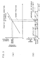
- Figs. 3 and 4 are diagrammatic representations illustrating a method of setting a target position. The flow charts of Figs. 2A and 2B are described with reference to Figs. 3 and 4.
- output values of the absolute encoders (A/Es) 55 and 56 for the master spindle 13 and the slave spindle 19 are read by way of the drive CPU 36 and the RAM 35.
- Such output values of the absolute encoders 55 and 56 can represent values within an angular range corresponding to 50 rotations of the main spindles.
- the output values of the absolute encoders 55 and 56 represent angular positions within the range from 0 degree to 18,000 degrees.
- the CPU 31 calculates a current position CM of the master spindle 13 and a current position CS of the slave spindle 19 in accordance with the output values of the absolute encoders 55 and 56, and stores in the RAM 32 data indicating the current positions CM and CS.
- step 102 it is judged whether or not an operation preparing switch SW1 of the operation panel 45 has been changed over from an off-state to an on-state, that is, whether or not an instruction for preparation for operation has just been provided.
- the result of judgment at step 102 is YES only in case the operation preparing switch SW1 has been changed over from an off-state to an on-state, and in this instance, the current process of the CPU 31 advances to step 104 which constitutes a deviation calculating means.
- step 106 it is judged whether or not the absolute value of the deviation calculated at step 104 exceeds 180 degrees which is a half cycle of rotation of the main spindles.
- the result of judgment at step 106 is NO, and the process of the CPU 31 advances to step 108.
- step 108 magnitudes of the master spindle current position CM and the slave spindle current position CS are compared with each other. In other words, it is judged whether or not the following inequality is satisfied; CM ⁇ CS Satisfaction of the inequality signifies that the master spindle current position CM precedes to the slave spindle current position CS within a range smaller than 180 degrees in the forward direction of rotation.
- the result of judgment at step 108 is YES, and in this instance, the process of the CPU 31 advances to step 110 at which the master spindle current position CM is set as a target position OV, whereafter the process of the CPU 31 advances to step 112.
- step 108 dissatisfaction of the inequality at step 108 signifies that the slave spindle current position CS precedes to the master spindle current position CM within a range smaller than 180 degrees in the forward direction of rotation (refer to (a) and (b) of Fig. 3). Accordingly, in case it is judged that the inequality is not satisfied, the process of the CPU 31 advances to step 116.
- step 116 the slave spindle current position CS is set as a target position OV, and after then, the process of the CPU 31 advances to step 112.
- step 112 it is judged whether or not the operation preparing switch SW1 is in an on-state.
- the process of the CPU 31 advances to step 114.
- step 114 a positioning instruction is provided to the drive CPU 36 together with the target position OV, thereby completing the execution of the program for one cycle.
- the drive CPU 36 Upon reception of the position instruction, the drive CPU 36 executes positioning control of the master spindle 13 and the slave spindle 19. In such positioning control, a distance to the thus provided target position OV is interpolated for each fixed very short period of time to produce an interpolation target position, and a deviation of the interpolation target position from the detected current position CM or CS is calculated. Then, a velocity signal corresponding to the thus calculated deviation is delivered to the digital to analog converter 51 or 53. Then, when the interpolation target position reaches to the target position OV to reduce the deviation between the target position OV and the master spindle current position CM or the slave spindle current position CS to zero, the velocity signal is reduced to zero. Consequently, the master spindle 13 and the slave spindle 19 are both positioned to the target position OV.
- step 106 in case it is judged at step 106 that the absolute value
- step 118 magnitudes of the master spindle current position CM and the slave spindle current position CS are compared with each other similarly as at step 108.
- ⁇ 180° where n is a value which represents a number of rotations by which the slave spindle 19 follows the master spindle 13.
- the slave spindle offset position SOF and the slave spindle current position CS are equal in phase to each other. Meanwhile, the slave spindle current position CS which is supervised by the CPU 31 is corrected to the slave spindle offset position SOF. Namely, the data stored in RAM 32 indicating the slave current position CS is replaced with data indicating the offset position SOF.
- step 122 magnitudes of the master spindle current position CM and the slave spindle offset position SOF are compared with each other. In particular, it is judged whether or not the following inequality is satisfied: CM ⁇ SOF
- step 124 the target position OV is set as the master spindle current position CM which precedes. Then, the process of the CPU 31 advances to step 112, and then, if it is judged at step 112 that the operation preparing switch SW1 is in an on-state similarly as described hereinabove, the process of the CPU 31 advances to step 114 at which a positioning instruction is delivered to the drive CPU 36 together with the target position OV.
- the slave spindle 19 is positioned so that the position thereof may be equal in phase to the master spindle current position CM, while the master spindle 13 is held at the original position in a servo locked state because the master spindle current position CM is equal to the target position OV.
- the angle of rotation of the slave spindle 19 is within 180 degrees, because the data indicating the slave current position CS has been replaced with the data indicating the slave spindle offset position SOF.
- the slave spindle offset position SOF is set as the target position OV at step 126.
- the process of the CPU 31 advances by way of the step 112 to step 114 at which a positioning instruction is delivered together with the target position OV.
- the master spindle 13 is rotated to be positioned to the same phase as the slave spindle 19, while the slave spindle 19 is held at the original position in a servo locked state because the data indicating the slave current position CS has been replaced with the data indicating the offset position SOF which is equal to the target position OV.
- the angle of rotation of the master spindle 13 is within 180 degrees in the forward direction of rotation, because the target position OV is equal to the slave spindle offset position SOF.
- step 118 in case it is judged at step 118 that the slave spindle current position CS precedes to the master spindle current position CM in the forward direction of rotation, the process of the CPU 31 advances to step 128.
- n which satisfies the following inequality is calculated similarly as at step 120:
- MOF CM + 360°x n
- the master spindle current position CM which is supervised by the CPU 31 is corrected to the master spindle offset position MOF. Namely, the data stored in RAM 32 indicating the master current position CM is replaced with the data indicating the offset position MOF.
- magnitudes of the master spindle offset position MOF and the slave spindle current position CS are compared with each other similarly as at step 122. In other words, it is judged whether or not the following inequality is satisfied: MOF ⁇ CS
- the master spindle offset position MOF is set as the target position OV at step 132. Then, the process of the CPU 31 advances by way of step 112 to step 114 at which a positioning instruction is delivered to the drive CPU 36 together with the target position OV. As a result, the slave spindle 19 is rotated to be positioned to the same phase as the master spindle 13, while the master spindle 13 is held at the original position in a servo locked state because the data indicating the master spindle current position CM has been replaced with the data indicating the master spindle offset position MOF which is equal to the target position OV. In this instance, the angle of rotation of the slave spindle 19 is within 180 degrees in the forward direction of rotation, because the target position OV is equal to the master spindle offset position MOF.
- step 130 in case it is judged at step 130 that the slave spindle current position CS precedes to the master spindle offset position MOF in the forward direction of rotation, the process of the CPU 31 advances to step 134. Then at step 134, the slave spindle current position CS is set as the target position OV. The process of the CPU 31 then advances by way of step 112 to step 114 at which a positioning instruction is delivered to the drive CPU 36 together with the target position OV.
- the master spindle 13 which follows the slave spindle 19 is rotated to be positioned to the same phase as the slave spindle 19 which precedes, while the slave spindle 19 is held at the original position in a servo locked state because the slave spindle current position CS is equal to the target position OV.
- the angle of rotation of the master spindle 13 is within 180 degrees in the forward direction of rotation, because the data indicating the master current position CM has been replaced with the data indicating the offset position MOF.
- a first target position setting means is attained by the steps 106, 108 and 110 while an offset means is attained by the steps 106, 118, 120 and 128. Further, a second target position setting means is attained by the steps 122, 124, 126, 130, 132 and 134.
- a detected current position when a detected current position is to be offset, it is offset in the forward direction of rotation.
- the current position in supervision of the following main spindle is advanced by an amount equal to an integral number of times a cycle of rotation of the main spindles by offset correction.
- the current position in supervision of the preceding main spindle may alternatively be retracted by an amount equal to an integral number of times a cycle of rotation of the main spindles by offset correction.
- one of current positions in supervision of the two main spindles should be corrected by offset correction so that the deviation between the current positions may be smaller than one half of a cycle of rotation of the main spindles.
- a synchronous control system for a pair of spindles of a machine tool including a master spindle and a slave spindle.
- Current positions of the main spindles are detected, and a deviation between the detected current positions is calculated.
- the current position of one of the main spindles which precedes in the forward direction of rotation is determined as a target position for positioning.
- the detected current position of the master spindle or the slave spindle is offset by an amount equal to an integral number of times 180 degrees so that the deviation between current positions of the main spindles after such offset is within 180 degrees.
Landscapes
- Engineering & Computer Science (AREA)
- Human Computer Interaction (AREA)
- Manufacturing & Machinery (AREA)
- Physics & Mathematics (AREA)
- General Physics & Mathematics (AREA)
- Automation & Control Theory (AREA)
- Numerical Control (AREA)
- Control Of Position Or Direction (AREA)
Applications Claiming Priority (2)
| Application Number | Priority Date | Filing Date | Title |
|---|---|---|---|
| JP1049473A JPH0649260B2 (ja) | 1989-02-28 | 1989-02-28 | 同期制御装置 |
| JP49473/89 | 1989-02-28 |
Publications (2)
| Publication Number | Publication Date |
|---|---|
| EP0385347A2 true EP0385347A2 (de) | 1990-09-05 |
| EP0385347A3 EP0385347A3 (de) | 1992-02-19 |
Family
ID=12832122
Family Applications (1)
| Application Number | Title | Priority Date | Filing Date |
|---|---|---|---|
| EP19900103700 Ceased EP0385347A3 (de) | 1989-02-28 | 1990-02-26 | Synchrones Steuerungssystem und Verfahren dafür |
Country Status (3)
| Country | Link |
|---|---|
| US (1) | US4988937A (de) |
| EP (1) | EP0385347A3 (de) |
| JP (1) | JPH0649260B2 (de) |
Cited By (2)
| Publication number | Priority date | Publication date | Assignee | Title |
|---|---|---|---|---|
| WO2009130336A1 (es) * | 2008-04-21 | 2009-10-29 | Bost Machine Tools Company, S.A. | Máquina y método para mecanizar cigüeñales de grandes dimensiones |
| CN110262291A (zh) * | 2018-03-12 | 2019-09-20 | 欧姆龙株式会社 | 控制装置、控制方法以及存储介质 |
Families Citing this family (7)
| Publication number | Priority date | Publication date | Assignee | Title |
|---|---|---|---|---|
| EP0385459A3 (de) * | 1989-03-02 | 1990-11-14 | Toyoda Koki Kabushiki Kaisha | Gerät zur Synchronisierkontrolle |
| WO1990015474A1 (en) * | 1989-06-09 | 1990-12-13 | Hitachi, Ltd. | Motor controller |
| JP2824588B2 (ja) * | 1989-08-24 | 1998-11-11 | 株式会社エスジー | サーボモータ同期制御方式 |
| JPH0511853A (ja) * | 1991-06-28 | 1993-01-22 | Matsushita Electric Ind Co Ltd | 2軸同期駆動装置 |
| DE19883028T1 (de) * | 1998-12-24 | 2002-02-14 | Mitsubishi Electric Corp | Numerisches Steuergerät |
| JP3680064B2 (ja) * | 2003-04-21 | 2005-08-10 | ファナック株式会社 | 数値制御装置 |
| JP4070744B2 (ja) * | 2004-04-28 | 2008-04-02 | ファナック株式会社 | 同期制御装置 |
Citations (4)
| Publication number | Priority date | Publication date | Assignee | Title |
|---|---|---|---|---|
| US3465217A (en) * | 1965-02-26 | 1969-09-02 | Collins Radio Co | Digitalized shaft rotation direction control |
| EP0077178A1 (de) * | 1981-10-09 | 1983-04-20 | Fanuc Ltd. | Motorregelungssystem für Gleichlaufbetrieb |
| FR2577698A1 (fr) * | 1985-02-18 | 1986-08-22 | Forest Line Sa | Procede et installation de commande des deplacements simultanes des deux extremites d'un portique qui porte une tete d'usinage de precision a grande vitesse |
| FR2618920A1 (fr) * | 1987-07-29 | 1989-02-03 | Trt Telecom Radio Electr | Dispositif de recopie d'un mouvement pour la conservation du couplage entre deux axes mobiles dans un plan |
Family Cites Families (13)
| Publication number | Priority date | Publication date | Assignee | Title |
|---|---|---|---|---|
| US3919614A (en) * | 1972-01-17 | 1975-11-11 | Warner Swasey Co | Dual-cycle cam grinding machine with electrical pulse operated wheel feed |
| US3906327A (en) * | 1973-08-28 | 1975-09-16 | Eaton Corp | Controlled velocity drive |
| US3906313A (en) * | 1973-12-03 | 1975-09-16 | Roger P Danis | Plural motor synchronizing apparatus |
| CH594918A5 (de) * | 1973-12-13 | 1978-01-31 | Hell Rudolf Dr Ing Gmbh | |
| FR2275816A1 (fr) * | 1974-06-19 | 1976-01-16 | Commissariat Energie Atomique | Dispositif de commande d'un organe mecanique avec retour d'effort |
| US4000449A (en) * | 1974-10-22 | 1976-12-28 | Westinghouse Electric Corporation | Electrical shaft system |
| US4405884A (en) * | 1981-04-27 | 1983-09-20 | Weber Harold J | Shaft position synchronization means for multiple synchronous induction motors |
| US4414495A (en) * | 1981-10-27 | 1983-11-08 | Kashifuji Works, Ltd. | Synchronism equipment for gear cutting machines |
| US4565950A (en) * | 1982-11-09 | 1986-01-21 | Ricoh Company, Ltd. | Servo system |
| DE3411651C1 (de) * | 1984-03-29 | 1989-04-27 | bso Steuerungstechnik GmbH, 6603 Sulzbach | Regelanordnung fuer den Gleichlauf mehrerer Antriebe |
| DE3677552D1 (de) * | 1985-06-26 | 1991-03-28 | Reishauer Ag | Verfahren und vorrichtung zur regelung der drehzahl einer spindel einer zahnradbearbeitungsmaschine. |
| EP0309824B1 (de) * | 1987-09-28 | 1991-11-13 | Siemens Aktiengesellschaft | Verfahren zur numerisch gesteuerten Lageregelung elektromotorisch angetriebener Achsen |
| JPH01129255A (ja) * | 1987-11-14 | 1989-05-22 | Dainippon Screen Mfg Co Ltd | 入力・出力分離型スキャナの制御方法 |
-
1989
- 1989-02-28 JP JP1049473A patent/JPH0649260B2/ja not_active Expired - Fee Related
-
1990
- 1990-02-26 EP EP19900103700 patent/EP0385347A3/de not_active Ceased
- 1990-02-27 US US07/485,567 patent/US4988937A/en not_active Expired - Lifetime
Patent Citations (4)
| Publication number | Priority date | Publication date | Assignee | Title |
|---|---|---|---|---|
| US3465217A (en) * | 1965-02-26 | 1969-09-02 | Collins Radio Co | Digitalized shaft rotation direction control |
| EP0077178A1 (de) * | 1981-10-09 | 1983-04-20 | Fanuc Ltd. | Motorregelungssystem für Gleichlaufbetrieb |
| FR2577698A1 (fr) * | 1985-02-18 | 1986-08-22 | Forest Line Sa | Procede et installation de commande des deplacements simultanes des deux extremites d'un portique qui porte une tete d'usinage de precision a grande vitesse |
| FR2618920A1 (fr) * | 1987-07-29 | 1989-02-03 | Trt Telecom Radio Electr | Dispositif de recopie d'un mouvement pour la conservation du couplage entre deux axes mobiles dans un plan |
Cited By (8)
| Publication number | Priority date | Publication date | Assignee | Title |
|---|---|---|---|---|
| WO2009130336A1 (es) * | 2008-04-21 | 2009-10-29 | Bost Machine Tools Company, S.A. | Máquina y método para mecanizar cigüeñales de grandes dimensiones |
| EP2281649A1 (de) * | 2008-04-21 | 2011-02-09 | Bost Machine Tools Company, S.A. | Maschine und verfahren zur maschinellen bearbeitung von grossen kurbelwellen |
| CN102036774A (zh) * | 2008-04-21 | 2011-04-27 | 白欧斯特机床股份公司 | 用于机加工大型曲轴的机械和方法 |
| EP2281649A4 (de) * | 2008-04-21 | 2011-05-11 | Bost Machine Tools Company S A | Maschine und verfahren zur maschinellen bearbeitung von grossen kurbelwellen |
| CN102036774B (zh) * | 2008-04-21 | 2012-12-19 | 白欧斯特机床股份公司 | 用于机加工大型曲轴的机械和方法 |
| US8555756B2 (en) | 2008-04-21 | 2013-10-15 | Bost Machine Tools Company, S .A. | Machine and method for machining large crankshafts |
| KR101539805B1 (ko) | 2008-04-21 | 2015-07-27 | 보스트 머신 툴스 컴퍼니, 에스.에이. | 대형 크랭크샤프트 가공 기계 및 가공 방법 |
| CN110262291A (zh) * | 2018-03-12 | 2019-09-20 | 欧姆龙株式会社 | 控制装置、控制方法以及存储介质 |
Also Published As
| Publication number | Publication date |
|---|---|
| JPH0649260B2 (ja) | 1994-06-29 |
| EP0385347A3 (de) | 1992-02-19 |
| US4988937A (en) | 1991-01-29 |
| JPH02232141A (ja) | 1990-09-14 |
Similar Documents
| Publication | Publication Date | Title |
|---|---|---|
| EP0187864A1 (de) | Regelsystem für beschleunigung-verlangsamung | |
| EP0397887B1 (de) | Verfahren zur korrektur eines bearbeitungsprogramms | |
| EP1720083B1 (de) | Numerische Steuerung | |
| US4988937A (en) | Synchronous control system and method therefor | |
| KR0139526B1 (ko) | 그라인딩 머신용 수치 제어장치 | |
| US4789943A (en) | Thread cutting control method | |
| EP0364593B1 (de) | Werkzeugmaschine mit zwei hauptspindeln | |
| US5181178A (en) | Spindle control command method | |
| WO1994023869A1 (en) | Nc machining apparatus | |
| US6225772B1 (en) | Acceleration/deceleration control method for numerical control, and numerical control device | |
| US6999844B2 (en) | Numerical controller | |
| GB2216294A (en) | Synchronous operation control system for numerically controlled machine | |
| EP0412164A1 (de) | Steuersystem zum durchführen eines tests | |
| JP3427800B2 (ja) | 数値制御装置 | |
| JPH0637883Y2 (ja) | 位置同期制御装置を備えたcnc研削盤 | |
| JPH03110603A (ja) | サーボモータのバックラッシュ補正制御方法 | |
| EP0128767B1 (de) | Numerisch gesteuertes Verfahren | |
| JPS63157207A (ja) | 数値制御装置 | |
| JPS63157206A (ja) | 数値制御装置 | |
| JP3729956B2 (ja) | 旋盤におけるネジの再加工方法 | |
| JPH05100723A (ja) | 工作機械の工具長補正方式 | |
| JP2788725B2 (ja) | 数値制御装置 | |
| EP0584370B1 (de) | Verfahren zum Schrauben einer Röhre mit Gewinden unterschiedlicher Hübe auf der Aussen- und Innenseite in ein Objekt | |
| JP2796335B2 (ja) | 数値制御装置 | |
| JPH06312341A (ja) | 数値制御装置 |
Legal Events
| Date | Code | Title | Description |
|---|---|---|---|
| PUAI | Public reference made under article 153(3) epc to a published international application that has entered the european phase |
Free format text: ORIGINAL CODE: 0009012 |
|
| AK | Designated contracting states |
Kind code of ref document: A2 Designated state(s): DE FR GB SE |
|
| PUAL | Search report despatched |
Free format text: ORIGINAL CODE: 0009013 |
|
| AK | Designated contracting states |
Kind code of ref document: A3 Designated state(s): DE FR GB SE |
|
| 17P | Request for examination filed |
Effective date: 19920529 |
|
| 17Q | First examination report despatched |
Effective date: 19931216 |
|
| STAA | Information on the status of an ep patent application or granted ep patent |
Free format text: STATUS: THE APPLICATION HAS BEEN REFUSED |
|
| 18R | Application refused |
Effective date: 19941112 |