EP0385284A1 - Verfahren und Vorrichtung zur verzugsarmen Wärmebehandlung von härtbaren Werkstoffen bei mindestens teilweise Rückführung des Kühlmediums und des Waschmittels zur Wiederverwendung - Google Patents
Verfahren und Vorrichtung zur verzugsarmen Wärmebehandlung von härtbaren Werkstoffen bei mindestens teilweise Rückführung des Kühlmediums und des Waschmittels zur Wiederverwendung Download PDFInfo
- Publication number
- EP0385284A1 EP0385284A1 EP19900103493 EP90103493A EP0385284A1 EP 0385284 A1 EP0385284 A1 EP 0385284A1 EP 19900103493 EP19900103493 EP 19900103493 EP 90103493 A EP90103493 A EP 90103493A EP 0385284 A1 EP0385284 A1 EP 0385284A1
- Authority
- EP
- European Patent Office
- Prior art keywords
- workpiece
- cooling
- treatment station
- tools
- station
- Prior art date
- Legal status (The legal status is an assumption and is not a legal conclusion. Google has not performed a legal analysis and makes no representation as to the accuracy of the status listed.)
- Withdrawn
Links
- 238000001816 cooling Methods 0.000 title claims abstract description 97
- 238000000034 method Methods 0.000 title claims abstract description 33
- 238000005406 washing Methods 0.000 title claims abstract description 16
- 239000000463 material Substances 0.000 title claims abstract description 10
- 238000004064 recycling Methods 0.000 title claims description 3
- 239000012530 fluid Substances 0.000 title abstract 2
- 238000011282 treatment Methods 0.000 claims abstract description 108
- 238000010438 heat treatment Methods 0.000 claims abstract description 44
- 239000002826 coolant Substances 0.000 claims abstract description 29
- 238000003825 pressing Methods 0.000 claims abstract description 28
- 210000000078 claw Anatomy 0.000 claims description 21
- 239000003599 detergent Substances 0.000 claims description 18
- 238000005496 tempering Methods 0.000 claims description 18
- 230000006698 induction Effects 0.000 claims description 14
- 230000001939 inductive effect Effects 0.000 claims description 5
- 239000007921 spray Substances 0.000 claims description 5
- 238000013459 approach Methods 0.000 claims description 4
- 239000003795 chemical substances by application Substances 0.000 abstract description 7
- 238000000137 annealing Methods 0.000 abstract 1
- 238000001035 drying Methods 0.000 description 5
- 238000010791 quenching Methods 0.000 description 3
- 230000000171 quenching effect Effects 0.000 description 3
- 230000035882 stress Effects 0.000 description 3
- 239000003921 oil Substances 0.000 description 2
- 239000004848 polyfunctional curative Substances 0.000 description 2
- 230000009897 systematic effect Effects 0.000 description 2
- 231100000331 toxic Toxicity 0.000 description 2
- 230000002588 toxic effect Effects 0.000 description 2
- 230000007723 transport mechanism Effects 0.000 description 2
- 240000009125 Myrtillocactus geometrizans Species 0.000 description 1
- 230000032683 aging Effects 0.000 description 1
- 239000003570 air Substances 0.000 description 1
- 238000007654 immersion Methods 0.000 description 1
- 239000007788 liquid Substances 0.000 description 1
- 238000004519 manufacturing process Methods 0.000 description 1
- 239000007769 metal material Substances 0.000 description 1
- 239000000203 mixture Substances 0.000 description 1
- 231100000241 scar Toxicity 0.000 description 1
- 230000036962 time dependent Effects 0.000 description 1
- XLYOFNOQVPJJNP-UHFFFAOYSA-N water Substances O XLYOFNOQVPJJNP-UHFFFAOYSA-N 0.000 description 1
Images


Classifications
-
- C—CHEMISTRY; METALLURGY
- C21—METALLURGY OF IRON
- C21D—MODIFYING THE PHYSICAL STRUCTURE OF FERROUS METALS; GENERAL DEVICES FOR HEAT TREATMENT OF FERROUS OR NON-FERROUS METALS OR ALLOYS; MAKING METAL MALLEABLE, e.g. BY DECARBURISATION OR TEMPERING
- C21D1/00—General methods or devices for heat treatment, e.g. annealing, hardening, quenching or tempering
- C21D1/62—Quenching devices
- C21D1/673—Quenching devices for die quenching
-
- C—CHEMISTRY; METALLURGY
- C21—METALLURGY OF IRON
- C21D—MODIFYING THE PHYSICAL STRUCTURE OF FERROUS METALS; GENERAL DEVICES FOR HEAT TREATMENT OF FERROUS OR NON-FERROUS METALS OR ALLOYS; MAKING METAL MALLEABLE, e.g. BY DECARBURISATION OR TEMPERING
- C21D1/00—General methods or devices for heat treatment, e.g. annealing, hardening, quenching or tempering
- C21D1/34—Methods of heating
- C21D1/42—Induction heating
-
- C—CHEMISTRY; METALLURGY
- C21—METALLURGY OF IRON
- C21D—MODIFYING THE PHYSICAL STRUCTURE OF FERROUS METALS; GENERAL DEVICES FOR HEAT TREATMENT OF FERROUS OR NON-FERROUS METALS OR ALLOYS; MAKING METAL MALLEABLE, e.g. BY DECARBURISATION OR TEMPERING
- C21D9/00—Heat treatment, e.g. annealing, hardening, quenching or tempering, adapted for particular articles; Furnaces therefor
- C21D9/0068—Heat treatment, e.g. annealing, hardening, quenching or tempering, adapted for particular articles; Furnaces therefor for particular articles not mentioned below
-
- Y—GENERAL TAGGING OF NEW TECHNOLOGICAL DEVELOPMENTS; GENERAL TAGGING OF CROSS-SECTIONAL TECHNOLOGIES SPANNING OVER SEVERAL SECTIONS OF THE IPC; TECHNICAL SUBJECTS COVERED BY FORMER USPC CROSS-REFERENCE ART COLLECTIONS [XRACs] AND DIGESTS
- Y02—TECHNOLOGIES OR APPLICATIONS FOR MITIGATION OR ADAPTATION AGAINST CLIMATE CHANGE
- Y02P—CLIMATE CHANGE MITIGATION TECHNOLOGIES IN THE PRODUCTION OR PROCESSING OF GOODS
- Y02P10/00—Technologies related to metal processing
- Y02P10/20—Recycling
-
- Y—GENERAL TAGGING OF NEW TECHNOLOGICAL DEVELOPMENTS; GENERAL TAGGING OF CROSS-SECTIONAL TECHNOLOGIES SPANNING OVER SEVERAL SECTIONS OF THE IPC; TECHNICAL SUBJECTS COVERED BY FORMER USPC CROSS-REFERENCE ART COLLECTIONS [XRACs] AND DIGESTS
- Y02—TECHNOLOGIES OR APPLICATIONS FOR MITIGATION OR ADAPTATION AGAINST CLIMATE CHANGE
- Y02P—CLIMATE CHANGE MITIGATION TECHNOLOGIES IN THE PRODUCTION OR PROCESSING OF GOODS
- Y02P10/00—Technologies related to metal processing
- Y02P10/25—Process efficiency
Definitions
- the invention relates to a method and a device for low-distortion heat treatment of hardenable materials, with at least partial recycling of the cooling medium and the detergent for reuse.
- Heat treatments on workpieces aim to change the structure of metallic materials by heating and cooling and thus to achieve certain properties of the material at hand.
- a workpiece is generally hardened by heating to the material-specific hardening temperature, by holding it at this hardening temperature in turn according to material-specific requirements and subsequent quenching. After quenching, the workpiece is usually reheated (tempering), which reduces the hardness to a certain value and reduces the stresses. The tempering temperature in turn depends on the material at hand and the later use of the finished tool.
- Quenching is carried out using water, oils or air, which either directly or indirectly come into contact with the workpiece.
- the workpieces are subjected to a wash after the heat treatment, the detergent being mixed with the hardening agent, e.g. B. mixed hardening oil and are usually no longer separable from each other and must be supplied to an expensive and expensive disposal.
- the hardening agent e.g. B. mixed hardening oil
- the invention is therefore based on the object of a method and a device for the series, low-distortion heat treatment of hardenable materials with at least partial return of the cooling medium and To create detergent for reuse by separating the hardening agent from the workpiece in an efficient manner, and to reuse this separate hardening agent and only then to wash the workpiece, whereby the hardening agent and on the other hand the detergent have a longer service life, which makes it possible will carry out the heating to the hardening temperature and the cooling of the workpiece using the induction method in only one station, the device being suitable for direct or indirect cooling with liquid cooling medium.
- the starting is again carried out by induction and the cooling indirectly or directly in a second treatment station, cooling tools optionally being integrated in this second treatment station, which shield certain parts of the workpiece from the required tempering temperature.
- cooling tools optionally being integrated in this second treatment station, which shield certain parts of the workpiece from the required tempering temperature.
- the heat treatment takes place in combined cooling and pressing tools in order to ensure low-distortion heat treatment.
- this method and the device have only two treatment stations, while in the case of direct cooling, which is carried out by changing tools, various intermediate treatment stations are provided for the centrifuging of the cooling medium, washing and drying.
- the essence of the invention is, among other things, to subject the workpiece to the treatments in the respective stations with rotation.
- At least one post-treatment station is also attached to the device, in which, for example, the "artificial aging" of the workpieces takes place.
- the workpiece is fed to at least one intermediate treatment station in which the cooling medium used for direct cooling is spun off, the workpiece is washed, dried and then fed to the second treatment station.
- the supply of the workpiece for heat treatment can alternatively take place in a horizontal or vertical position, it being a special feature of the invention that the workpiece is subjected to the heat treatment with a rotational movement.
- the feed to the intermediate treatment station also takes place, the workpiece also being subjected to the intermediate treatment while rotating.
- An expedient embodiment of the inductor consists in the design as a claw, which approaches the workpiece horizontally in the first treatment station and heats it inductively while rotating the workpiece, the induction claw being U-shaped in cross-section and in this case being one towards the center of the workpiece in The shape of a circular segment tapers out to reduce the intensity of the inductive heating energy to the workpiece center.
- the inductor claw arranged in the second treatment station preferably approaches the workpiece at an angle that deviates from the horizontal and inductively heats the workpiece without contact while rotating the workpiece, the induction claw having a congruent design, like the induction claw in the first treatment station.
- plate-shaped and ring-shaped designs of the inductor can also be used.
- ring-shaped cooling takes place at workpiece parts by storing the workpiece in cooling tools during inductive heating and thus shielding it from the tempering temperature of the parts to be treated.
- the device for carrying out the method provides a receptacle and a dispensing magazine for the workpieces to be treated, between which a first treatment station for heating, cooling and deforming the workpiece to be treated and a second treatment station for tempering and cooling the workpiece to be treated are arranged, which, in turn, have at least one intermediate treatment station and one post-treatment station arranged or subordinated.
- the first treatment station has a horizontally approachable inductor which ensures the rotation of the workpiece, as well as exchangeable, vertically displaceable cooling and pressing tools and which second treatment station has an inductor which ensures the rotation of the workpiece and can be approached at an angle deviating from the right angle to the workpiece axis, as well as exchangeable, vertically movable cooling and pressing tools.
- Rotary cooling tools are provided for holding the workpiece, for receiving and dispensing the Workpieces vertically movable gripping tools function.
- the cooling and pressing tools For the purpose of receiving centering bolts, the cooling and pressing tools have bores which run coaxially to the workpiece hub, the centering bolt being rotatably mounted in the device.
- a special embodiment of the invention provides that the cooling tools can be moved vertically and has the shape of the finished workpiece on the side facing the workpiece.
- the segment cooling tools are rotatably arranged in the cooling tool by means of bearings.
- the cooling and pressing tools have cooling channels for indirect cooling, while the cooling tools have cooling slots for the purpose of direct cooling.
- the intermediate treatment stations have washing spray nozzles and compressed air nozzles for the purpose of washing and drying, wherein in a particular embodiment of the invention it is provided that several intermediate treatment stations are combined to form a treatment station in which the washing spray nozzles and the compressed air nozzles are integrated.
- the centering bolts are rotatable and vertically movable in the device, as are the cooling and pressing tools.
- the intermediate treatment station consists of at least one station receiving the workpiece, in which the cooling medium is separated from the workpiece and this is washed and dried, the intermediate treatment station comprising a rotatable mandrel for receiving the workpiece and at least one nozzle assembly directed towards the workpiece, from the detergent and / or compressed air emerges, and provides discharge and return lines for the cooling medium or detergent thrown off the workpiece.
- At least one lockable discharge line is provided in the intermediate treatment station for the purpose of returning the centrifuged cooling medium.
- the intermediate treatment station provides at least one return line.
- a discharge line for the introduced compressed air is provided when the intermediate treatment station is airtight and gas-tight.
- the nozzle arrangement has a multiplicity of outlet openings which are directed onto the workpiece on both sides. It is a special feature of the invention that the outlet openings of the nozzles are directed at the workpiece at an angle deviating from 90 relative to the workpiece horizontal.
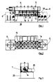
- Figures 1 to 3 show the device according to the invention from different views.
- the device consists of a machine base with a lower part 28 running through for all stations, on which the transport mechanism (not described in more detail here) is installed.
- a magazine 2 which is designed as a turntable for receiving, for example, four magazine bars
- the workpiece 1 is picked up by means of a gripping tool 18, preferably a magnetic gripper, and presented to the transport mechanism.
- the workpiece is picked up via a rotating mandrel, which also functions as a centering pin 20.
- This is moved up to pick up the workpiece 1.
- An inductor claw 14 is arranged to be horizontally movable on a carriage 29.
- This first treatment station 3 functions as a hardening station. After the workpiece 1 on the Centering pin 20 is fixed, the inductor claw 14 moves horizontally to the workpiece 1, the workpiece 1 being held under rotation.
- the workpiece is thus heated uniformly to the desired hardening temperature.
- the inductor claw 14 is removed from the workpiece 1 and the workpiece 1 is picked up by the cooling and pressing tools 12, 13. This can be done either by moving the centering bolt 20 with the workpiece 1 into the lower cooling and pressing tool 12 and then lowering it by the cooling and pressing tool 13, or by lifting and / or lowering the cooling and pressing tools 12 and 13.
- the cooling and pressing tools 12, 13 are arranged interchangeably in the device. Depending on the existing requirements, these can be designed as indirect or direct cooling tools. If it is necessary to cool the workpiece directly, the coolant flows through cooling slots directly to the workpiece 1. In this first treatment station 3, the parts are deformed under pressure at the same time. The workpiece 1 is then fed to the first intermediate treatment station 7, in which the cooling medium is spun off while the workpiece 1 is rotating.
- the next step is the feeding of the workpiece 1 to the second intermediate treatment station 9, in which the workpiece 1 is washed.
- washing spray nozzles 26 are arranged in the device.
- the next intermediate treatment station 10 dries the workpiece 1, for which purpose compressed air nozzles 27 are provided in the device.
- the workpieces in the intermediate treatment stations 7, 9 and 10 are always treated with the workpiece 1 being rotated.
- the intermediate treatment stations 9 (washing) and 10 (drying) and, if appropriate, the intermediate treatment station 7 (centrifuging) also apply to combine one station.
- the workpiece 1 is then fed to the actual second treatment station 4.
- the workpiece is tempered to a material-specific temperature, which in turn takes place with an inductor claw 15.
- the inductor claw 15 can be approached at an angle to the workpiece.
- the cooling and pressing tools 12, 13 are closed again. Direct or indirect cooling can now be carried out again.
- a special feature of the invention is that in this second treatment station 4 certain workpiece sub-locations can be shielded from the tempering temperature. This is described in more detail in FIG. 5.
- the second treatment station 4 is preferably assigned one or more post-treatment stations 11. This can e.g. B. be a post-treatment station in which the workpiece is "artificially aged".
- FIG. 4 shows a schematic representation of the first treatment station 3.
- the centering pin 20 can be moved vertically and rotated in the device. After the workpiece 1 (here still as a blank) is picked up, the induction claw 14 moves towards the workpiece 1.
- the induction claw 14 is U-shaped, so that it surrounds the workpiece in such a way that rotation of the workpiece 1 is ensured. This results in a uniform and controlled heating of the workpiece.
- the cooling and pressing tools 12 and 13 close and the heated workpiece 1 first takes on its shape, since the cooling and pressing tools 12, 13 simultaneously function as matrices. After the workpiece 1 is inside the closed cooling and pressing tools 12, 13, the cooling begins.
- the cooling and pressing tools are designed for indirect cooling.
- cooling channels 24 are arranged within the tools.
- a cooling and pressing tool with cooling slots 25 (as indicated in FIG. 4a), which functions for direct cooling, is to be exchanged for the indirect cooling tool.
- the cooling tool 12 has a through hole 22.
- FIG. 5 shows the second treatment station 4. It has the same structure as the first treatment station, with the difference that the induction claw 15 can be approached at an angle to the workpiece, which is already deformed.
- cooling tools 16, 17 arranged rotatably by means of bearings 23 are provided here.
- the centering pin 20, which moves into the workpiece scar 21, is also received by the cooling tools 16, 17.
- these cooling tools 16, 17 also have cooling channels 5 provided for indirect cooling.
- a cooling medium 8 flows through the cooling channels 5 and 24, as in the first treatment station 3.
- inductor claws for heating the workpiece.
- inductors in disk or plate form is also within the meaning of this invention.
- the rotation of the workpiece may not be necessary.
- Figure 6 shows a schematic representation of the Intermediate treatment station in an embodiment in which centrifuging the cooling medium, washing and drying the workpiece are combined.
- This consists of a station in which the cooling medium 8 is separated from the workpiece 1 and the workpiece 1 is subjected to washing and drying.
- this station has a holding mandrel 30 for fixing the workpiece 1.
- the workpiece 1 is set in rotation by means of the rotatable mandrel 30. Due to the centrifugal force, the cooling medium 8 is thrown off the workpiece. The cooling medium 8 is fed for reuse via the discharge line 33.
- the discharge line 33 can preferably be shut off.
- nozzle arrangement 26 in station 3, from which the detergent 31 emerges.
- this nozzle arrangement 26 can also be used for the discharge of compressed air 32.
- a separate nozzle arrangement 27 must be provided for the compressed air outlet (arranged in dashed lines).
- the detergent 31 is returned via the discharge line 34 and, given the conventional applications, has a service life that is five times longer. So it can be used again for washing. If necessary, the discharge line 34 can be followed by a separating device which again largely separates the detergent from the hardening agent.
- a discharge air line 35 is provided for this purpose.
- the nozzle outlet openings 36 are arranged variably in their outlet direction in accordance with the workpiece conditions.
- Figure 7 shows a further embodiment of the intermediate treatment station, in which the receiving housing is formed in two parts.
- the upper part 37 can be moved vertically and can be placed on the lower part 38 so that it can be closed. After the workpiece 1 has been inserted into the intermediate treatment station, the upper part 37 seals against the lower part 38, a protruding arm 39 being arranged in the upper part 37 and a protruding arm 40 being arranged on the lower part 38, which nozzle openings 36 are for washing or for have the compressed air.
- the present invention provides a method and a device which adapts to a wide variety of requirements and uses induction claws for heating the workpiece while rotating the workpiece, in which the rotation of the workpiece remains guaranteed during the heating.
- the possibility of supplying workpieces to different heat treatments in one device, cooling them directly or indirectly and simultaneously Checking and achieving shielding of certain workpiece sub-surfaces from the tempering temperature enables low-distortion, series hardening of a wide variety of workpieces, with the coolant being recycled for example at a rotation of 1400 rpm up to 80%.
Landscapes
- Chemical & Material Sciences (AREA)
- Engineering & Computer Science (AREA)
- Physics & Mathematics (AREA)
- Thermal Sciences (AREA)
- Crystallography & Structural Chemistry (AREA)
- Mechanical Engineering (AREA)
- Materials Engineering (AREA)
- Metallurgy (AREA)
- Organic Chemistry (AREA)
- Heat Treatment Of Articles (AREA)
Applications Claiming Priority (2)
| Application Number | Priority Date | Filing Date | Title |
|---|---|---|---|
| DE19893906425 DE3906425C1 (cg-RX-API-DMAC7.html) | 1989-03-01 | 1989-03-01 | |
| DE3906425 | 1989-03-01 |
Publications (1)
| Publication Number | Publication Date |
|---|---|
| EP0385284A1 true EP0385284A1 (de) | 1990-09-05 |
Family
ID=6375208
Family Applications (1)
| Application Number | Title | Priority Date | Filing Date |
|---|---|---|---|
| EP19900103493 Withdrawn EP0385284A1 (de) | 1989-03-01 | 1990-02-23 | Verfahren und Vorrichtung zur verzugsarmen Wärmebehandlung von härtbaren Werkstoffen bei mindestens teilweise Rückführung des Kühlmediums und des Waschmittels zur Wiederverwendung |
Country Status (2)
| Country | Link |
|---|---|
| EP (1) | EP0385284A1 (cg-RX-API-DMAC7.html) |
| DE (1) | DE3906425C1 (cg-RX-API-DMAC7.html) |
Citations (5)
| Publication number | Priority date | Publication date | Assignee | Title |
|---|---|---|---|---|
| DE919892C (de) * | 1944-03-14 | 1954-11-08 | Eugen Bellmann | Tauchvorrichtung mit Quette zum Abschrecken von Werkstuecken, insbesondere Blechen |
| FR2125831A5 (cg-RX-API-DMAC7.html) * | 1971-02-16 | 1972-09-29 | Peddinghaus Paul Ferd Fa | |
| WO1986005820A1 (fr) * | 1985-03-27 | 1986-10-09 | Jenny Pressen Ag | Procede et installation de traitement thermomecanique en serie de pieces a usiner causant peu de deformations, et application du procede |
| FR2593192A1 (fr) * | 1986-01-20 | 1987-07-24 | Stein Heurtey | Installation de chauffage et de trempe sous presse de pieces metalliques |
| DE8902418U1 (de) * | 1989-03-01 | 1989-04-27 | Karl Heess GmbH & Co Maschinenbau, 6840 Lampertheim | Vorrichtung zur verzugsarmen Wärmebehandlung von härtbaren Werkstoffen |
-
1989
- 1989-03-01 DE DE19893906425 patent/DE3906425C1/de not_active Expired - Fee Related
-
1990
- 1990-02-23 EP EP19900103493 patent/EP0385284A1/de not_active Withdrawn
Patent Citations (5)
| Publication number | Priority date | Publication date | Assignee | Title |
|---|---|---|---|---|
| DE919892C (de) * | 1944-03-14 | 1954-11-08 | Eugen Bellmann | Tauchvorrichtung mit Quette zum Abschrecken von Werkstuecken, insbesondere Blechen |
| FR2125831A5 (cg-RX-API-DMAC7.html) * | 1971-02-16 | 1972-09-29 | Peddinghaus Paul Ferd Fa | |
| WO1986005820A1 (fr) * | 1985-03-27 | 1986-10-09 | Jenny Pressen Ag | Procede et installation de traitement thermomecanique en serie de pieces a usiner causant peu de deformations, et application du procede |
| FR2593192A1 (fr) * | 1986-01-20 | 1987-07-24 | Stein Heurtey | Installation de chauffage et de trempe sous presse de pieces metalliques |
| DE8902418U1 (de) * | 1989-03-01 | 1989-04-27 | Karl Heess GmbH & Co Maschinenbau, 6840 Lampertheim | Vorrichtung zur verzugsarmen Wärmebehandlung von härtbaren Werkstoffen |
Non-Patent Citations (1)
| Title |
|---|
| METAL SCIENCE & HEAT TREATMENT, Band 18, Nrs. 9-10, September-Oktober 1976, Seiten 769-773; V.I. DUBEIKOVSKII et al.: "Automated heat treatment line for friction disks of the Kirovets K-701 tractor" * |
Also Published As
| Publication number | Publication date |
|---|---|
| DE3906425C1 (cg-RX-API-DMAC7.html) | 1990-11-22 |
Similar Documents
| Publication | Publication Date | Title |
|---|---|---|
| EP0215032B1 (de) | Verfahren und anlage zur serienmässigen, verzugsarmen thermomechanischen behandlung von werkstücken sowie anwendung des verfahrens | |
| DE102009045200A1 (de) | Verfahren und Vorrichtung zum Bearbeiten von Bauteilen elektrischer Maschinen | |
| DE2628254A1 (de) | Vorrichtung zur handhabung von mit oeffnungen versehenen gegenstaenden | |
| DE1463870A1 (de) | Verfahren und Vorrichtung zum Auftragen von UEberzuegen | |
| DE102016115819A1 (de) | Bremsscheiben-Werkzeug zum Bearbeiten eines Bremsscheiben-Rohlings, Bremsscheiben-Herstellanlage und Verfahren zum Herstellen einer Bremsscheibe | |
| DE2603618A1 (de) | Verfahren und vorrichtung zur waermebehandlung von stahl | |
| DE3831294A1 (de) | Verfahren zum kopierschleifen von zylindrischen und sphaerischen oberflaechen und vorrichtung zur durchfuehrung des verfahrens | |
| DE2314858A1 (de) | Einrichtung zum bearbeiten von metallischen werkstuecken | |
| DE3523239C2 (de) | Vorrichtung zum gleichzeitigen Polieren der Wellenabschnitte und Stirnflächen und zum Abfasen der Zahnkanten von Ritzelwellen | |
| DE102006018406B4 (de) | Verfahren zum Erwärmen von Werkstücken, insbesondere zum Presshärten vorgesehener Blechteile | |
| EP0722375A1 (de) | Bearbeitungszentrum für kurbelwellen | |
| DE69805345T2 (de) | Vorrichtung zur Bearbeitung eines Werkstücks | |
| DE19915264C1 (de) | Verfahren zum induktiven Randschichthärten von hohlen Werkstücken | |
| DE1909353A1 (de) | Bearbeitungseinrichtung zum radialen Druckverformen von Werkstuecken | |
| DE3906425C1 (cg-RX-API-DMAC7.html) | ||
| DE19727375C1 (de) | Verfahren zum Erzeugen einer Hartschicht auf Wekzeugen, Verwendung einer Vorrichtung zur Durchführung des Verfahrens sowie Preßstempel und Pegel zur Herstellung von Hohlglas | |
| DE102016118270A1 (de) | Bremsscheiben-Werkzeug zum Bearbeiten eines Bremsscheiben-Rohlings, Bremsscheiben-Herstellanlage und Verfahren zum Herstellen einer Bremsscheibe | |
| DE8902418U1 (de) | Vorrichtung zur verzugsarmen Wärmebehandlung von härtbaren Werkstoffen | |
| DE3405420A1 (de) | Vorrichtung zum wechseln von werkzeugen in giessereimaschinen | |
| DE102018101226A1 (de) | Vorrichtung zum induktiven Härten von langgestreckten Werkstücken | |
| DE102022210392A1 (de) | Bearbeitungsvorrichtung | |
| DE3421169A1 (de) | Verfahren und vorrichtung zum automatischen uebergeben und spannen von werkstuecken | |
| DE7145834U (de) | Vorrichtung zum induktiven beheizen und abschrecken von langgestreckten werkstuecken | |
| EP1226899B1 (de) | Verfahren und Vorrichtung zur Bearbeitung von Werkstücken | |
| DE202010002818U1 (de) | Drehbearbeitungsmaschine |
Legal Events
| Date | Code | Title | Description |
|---|---|---|---|
| PUAI | Public reference made under article 153(3) epc to a published international application that has entered the european phase |
Free format text: ORIGINAL CODE: 0009012 |
|
| AK | Designated contracting states |
Kind code of ref document: A1 Designated state(s): AT BE CH DE DK ES FR GB GR IT LI LU NL SE |
|
| 17P | Request for examination filed |
Effective date: 19901214 |
|
| 17Q | First examination report despatched |
Effective date: 19920826 |
|
| STAA | Information on the status of an ep patent application or granted ep patent |
Free format text: STATUS: THE APPLICATION HAS BEEN WITHDRAWN |
|
| 18W | Application withdrawn |
Withdrawal date: 19930526 |