EP0384166A2 - Construction de diaphragme de compresseur - Google Patents
Construction de diaphragme de compresseur Download PDFInfo
- Publication number
- EP0384166A2 EP0384166A2 EP90101833A EP90101833A EP0384166A2 EP 0384166 A2 EP0384166 A2 EP 0384166A2 EP 90101833 A EP90101833 A EP 90101833A EP 90101833 A EP90101833 A EP 90101833A EP 0384166 A2 EP0384166 A2 EP 0384166A2
- Authority
- EP
- European Patent Office
- Prior art keywords
- shrouds
- vane
- turbine
- integrally
- casing
- Prior art date
- Legal status (The legal status is an assumption and is not a legal conclusion. Google has not performed a legal analysis and makes no representation as to the accuracy of the status listed.)
- Granted
Links
- 238000002485 combustion reaction Methods 0.000 claims abstract description 26
- 238000005304 joining Methods 0.000 claims description 3
- 230000000295 complement effect Effects 0.000 claims description 2
- 238000000034 method Methods 0.000 description 13
- 238000005336 cracking Methods 0.000 description 12
- 238000004519 manufacturing process Methods 0.000 description 9
- 230000000712 assembly Effects 0.000 description 8
- 238000000429 assembly Methods 0.000 description 8
- 238000003466 welding Methods 0.000 description 7
- 230000003068 static effect Effects 0.000 description 5
- 239000007789 gas Substances 0.000 description 4
- 238000005219 brazing Methods 0.000 description 3
- 238000006073 displacement reaction Methods 0.000 description 3
- 239000000446 fuel Substances 0.000 description 3
- 239000002184 metal Substances 0.000 description 3
- 229910052751 metal Inorganic materials 0.000 description 3
- 150000002739 metals Chemical class 0.000 description 3
- IJGRMHOSHXDMSA-UHFFFAOYSA-N Atomic nitrogen Chemical compound N#N IJGRMHOSHXDMSA-UHFFFAOYSA-N 0.000 description 2
- LYCAIKOWRPUZTN-UHFFFAOYSA-N Ethylene glycol Chemical compound OCCO LYCAIKOWRPUZTN-UHFFFAOYSA-N 0.000 description 2
- 238000010894 electron beam technology Methods 0.000 description 2
- 230000000977 initiatory effect Effects 0.000 description 2
- 230000000452 restraining effect Effects 0.000 description 2
- 238000005476 soldering Methods 0.000 description 2
- 229910045601 alloy Inorganic materials 0.000 description 1
- 239000000956 alloy Substances 0.000 description 1
- 239000010953 base metal Substances 0.000 description 1
- 238000005266 casting Methods 0.000 description 1
- 238000010276 construction Methods 0.000 description 1
- 238000005520 cutting process Methods 0.000 description 1
- 230000000694 effects Effects 0.000 description 1
- 230000005611 electricity Effects 0.000 description 1
- 238000005242 forging Methods 0.000 description 1
- 230000030279 gene silencing Effects 0.000 description 1
- WGCNASOHLSPBMP-UHFFFAOYSA-N hydroxyacetaldehyde Natural products OCC=O WGCNASOHLSPBMP-UHFFFAOYSA-N 0.000 description 1
- 239000007788 liquid Substances 0.000 description 1
- 238000013017 mechanical damping Methods 0.000 description 1
- 238000003801 milling Methods 0.000 description 1
- 229910052757 nitrogen Inorganic materials 0.000 description 1
- 125000006850 spacer group Chemical group 0.000 description 1
- 229910001220 stainless steel Inorganic materials 0.000 description 1
- 239000007858 starting material Substances 0.000 description 1
Images


Classifications
-
- F—MECHANICAL ENGINEERING; LIGHTING; HEATING; WEAPONS; BLASTING
- F04—POSITIVE - DISPLACEMENT MACHINES FOR LIQUIDS; PUMPS FOR LIQUIDS OR ELASTIC FLUIDS
- F04D—NON-POSITIVE-DISPLACEMENT PUMPS
- F04D29/00—Details, component parts, or accessories
- F04D29/40—Casings; Connections of working fluid
- F04D29/52—Casings; Connections of working fluid for axial pumps
- F04D29/54—Fluid-guiding means, e.g. diffusers
- F04D29/541—Specially adapted for elastic fluid pumps
- F04D29/542—Bladed diffusers
-
- F—MECHANICAL ENGINEERING; LIGHTING; HEATING; WEAPONS; BLASTING
- F01—MACHINES OR ENGINES IN GENERAL; ENGINE PLANTS IN GENERAL; STEAM ENGINES
- F01D—NON-POSITIVE DISPLACEMENT MACHINES OR ENGINES, e.g. STEAM TURBINES
- F01D9/00—Stators
- F01D9/02—Nozzles; Nozzle boxes; Stator blades; Guide conduits, e.g. individual nozzles
- F01D9/04—Nozzles; Nozzle boxes; Stator blades; Guide conduits, e.g. individual nozzles forming ring or sector
- F01D9/042—Nozzles; Nozzle boxes; Stator blades; Guide conduits, e.g. individual nozzles forming ring or sector fixing blades to stators
Definitions
- This invention relates generally to combustion or gas turbines, and more particularly to the compressor diaphragm assemblies used in such turbines.
- a typical combustion turbine is comprised generally of four basic portions: (1) an inlet portion; (2) a compressor portion; (3) a combustor portion; and (4) an exhaust portion. Air entering the combustion turbine at its inlet portion is compressed adiabatically in the compressor portion, and is mixed with a fuel and heated at a constant pressure in the combustor portion, thereafter being discharged through the exhaust portion with a resulting adiabatic expansion of the gases completing the basic combustion turbine cycle which is generally referred to as the Brayton, or Joule, cycle.
- a significant problem of fatigue cracking in the airfoil portion of inner-shrouded vanes exists, however, due to conventionally used methods of manufacturing such vanes.
- a welding process is used to join the vane airfoils to their respective inner and outer shrouds, such process resulting in a "heat-affected zone" at each weld joint.
- Crack initiation due to fatigue it has been found, more often than not occurs at such heat-affected zones. Therefore, it would be desirable not only to provide an improved compressor diaphragm assembly that would be resistant to fatigue cracking, but also to provide a method of fabricating such assemblies that would minimize processes which produce heat-affected zones.
- the outer shroud segment of this hypothetical vane airfoil would not be stably engaged with the casing of the combustion turbine until such time that a restraining moment could be generated by contact of the extremities of the outer shroud segment with the walls of the slot formed in the casing to receive the segment.
- the outer shroud segment would, thus, rotate within the clearance gap (provided in the casing slot to account for thermal expansion).
- use of the hypothetical vane airfoil in a combustion turbine would lead to a great deal of stress in the vicinity of the outer shroud segment and excessive translational and rotational displacements, each of which would be further exacerbated under dynamic stimuli. It would also be desirable, therefore, to provide an improved compressor diaphragm assembly that would avoid the above described instabilities of engagement.
- the present invention resides in a compressor diaphragm assembly for a combustion turbine having a casing, a rotor including a plurality of rotating blades which are axially disposed along a shaft having a plurality of discs, and one or more slots of a first predetermined cross-section formed circumferentially within the casing at a compressor portion of the turbine, wherein said diaphragm assembly includes a plurality of vane airfoils each having an inner shroud and an outer shroud formed integrally therewith with said outer shroud including an upper portion of a cross-section complementary to the first predetermined cross-section so as to be slidably engaged in the slots in the turbine casing; characterized in that load transfer means are provided so as to extend across and interconnect adjacent ones of said plurality of airfoils at their respective integrally-formed inner shrouds and integrally-formed outer shrouds.
- a typical electric-generating plant 10 utilizes a combustion turbine 12 (such as the model W-501D single shaft, heavy duty combustion turbine that is manufactured by the Combustion Turbine Systems Division of Westinghouse Electric Corporation).
- the plant 10 includes a generator 14 driven by the turbine 12, a starter package 16, an electrical package 18 having a glycol cooler 20, a mechanical package 22 having an oil cooler 24, and an air cooler 26, each of which support the operating turbine 12.
- Conventional means 28 for silencing flow noise associated with the operating turbine 12 are provided for at the inlet duct and at the exhaust stack of the plant 10, while conventional terminal means 30 are provided at the generator 14 for conducting the generated electricity therefrom.
- the turbine 12 is comprised generally of an inlet portion 32, a compressor portion 34, a combustor portion 36, and an exhaust portion 38.
- Air entering the turbine 12 at its inlet portion 32 is compressed adiabatically in the compressor portion 34, and is mixed with a fuel and heated at a constant pressure in the combustor portion 36.
- the heated fuel/air gases are thereafter discharged from the combustor portion 36 through the exhaust portion 38 with a resulting adiabatic expansion of the gases completing the basic combustion turbine cycle.
- Such thermodynamic cycle is alternatively referred to as the Brayton, or Joule, cycle.
- the compressor portion 34 is of an axial flow configuration having a rotor 40.
- the rotor 40 includes a plurality of rotating blades 42, axially disposed along a shaft 44, and a plurality of discs 46.
- Each adjacent pair of the plurality of rotating blades 42 is interspersed by one of a plurality of shrouded stationary vanes 48, mounted to the turbine casing 50 as explained in greater detail herein below with reference to Figs. 3 and 4, thereby providing a diaphragm assembly in conjunction with the discs 46 with stepped labyrinth interstage seals 52.
- a "heat-affected zone” is that portion of the base metal which has not been melted, but whose mechanical properties or microstructure have been altered by the heat of welding, brazing, soldering, or cutting.
- stainless steels alloys of the type utilized for the airfoils 54, inner shrouds 56 and outer shrouds 58 crack initiation due to fatigue more often than not occurs at such heat-affected zones 60.
- Fig. 3 illustrates an inner-shrouded vane 48 that is manufactured by the rolled constant section approach
- Fig. 4 illustrates an inner-shrouded vane 48 that is manufactured by the forged variable thickness-to-chord ratio approach.
- Fatigue cracking nevertheless, would still not be eliminated simply through the use of a hypothetical airfoil having an integrally formed inner and outer shroud, thereby doing away with the heat-affected zones 60.
- the outer shroud segment of this hypothetical vane airfoil would not be stably engaged with the casing of the combustion turbine until such time that a restraining moment could be generated by contact of the extremities of the outer shroud segment with the walls of the slot formed in the casing to receive the segment.
- the outer shroud 58 would, thus, rotate within the clearance gap (provided in the casing slot to account for thermal expansion).
- use of the hypothetical vane airfoil in a combustion turbine would lead to a great deal of stress in the vicinity of the outer shroud segment and excessive translational and rotational displacements, each of which would be further exacerbated under dynamic stimuli.
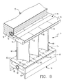
- the compressor diaphragm assembly 64 includes a plurality of vane airfoils 66, each such airfoil 66 having an integrally-formed inner shroud 68 and an integrally-formed outer shroud 70.
- the inner shroud 68 and outer shroud 70 of each of the airfoils 66 includes a groove 72 that is adapted to receive a connecting bar 74 to form load transfer means 76. Two or more adjacent ones of the plurality of airfoils 66 are coupled together by the load transfer means 76 and, thus, form the assembly 64.
- a seal carrier 78 comprising a plurality of segments 80, is suspended from the inner shroud 68, each such seal carrier segment 80 including at least one pair of disc-engaging seals 82, and being formed to engage the inner shrouds 68 of one or more vane airfoils 66.
- heat-affected zones are eliminated not only due to the plurality of vane airfoils' 66 being formed with integral inner shrouds 68 and integral outer shrouds 70, but also due to their being joined together by processes which use little or no heat at the critical airfoil to shroud junction. Furthermore, there are few if any instabilities of engagement between the vane airfoils 66 and the casing slot 75 (due either to static or dynamic stimuli) because of the load transfer means 76.
- each integrally-formed outer shroud 70 is joined to form an outer ring 84 with the connecting bars 74.
- each integrally-formed outer shroud 70 is also formed with a generally T-shaped cross-section for engagement with the slot 75 formed in the casing 50 of the turbine 12, held in place by conventional retaining screws 90.
- spacers 92 of varying sizes are provided to properly space the vane airfoils 66 one from the other.
- the integrally-formed inner shrouds 68 and outer shrouds 70 are respectively joined to adjacent ones of such integrally-formed inner shrouds 68 and outer shrouds 70 in order to prevent excessive translational and rotational displacements of the resulting compressor diaphragm assemblies 64 within the casing slots 75 of the turbine 12.
- Each vane airfoil 66 is connected to an adjacent vane airfoil 66, both at the integrally-formed inner shrouds 68 and at the integrally-formed outer shrouds 70, by the load transfer means 76 comprising the connecting bars 74.
- the slots 72 which are provided in the integrally-formed inner shrouds 68 and at the integrally- formed outer shrouds 70 may have substantially parallel sides as shown in Fig. 6 for use with rectangular-shaped connecting bars 74. As an alternative configuration, however, the slots 72 may be tapered at an angle ⁇ less than 90 degrees as shown in Fig. 7.
- compressor diaphragm assemblies 64 in accordance with the present invention may be easily formed by joining a plurality of vane airfoils 66 together, either by brazing, by electron beam welding, by laser welding (directions "A” or "B” shown in Fig. 6), by shrink fitting or simply by providing blade-type clearances (i.e., approximately 0.025 mm).
- the sides of the connecting bars 74 are defined by the angle ⁇ which can vary from zero (i.e., for parallel-sided slots 72), suitable for joining by electron beam welding in the directions A and B as shown in Fig. 6, to a taper of less than 90 degrees, suitable for shrinking or fitted assembly.
- the connecting bars 74 could be "shrunk” using liquid nitrogen or other suitable means and inserted within the slot 72 for expansion thereafter in the slot 72.
- the vane airfoils 64 could be heated to approximately 260°F, and the connecting bars 74 inserted therein, to provide a locked up system with low compressive and tensile stresses.
- blade type clearances could be provided between the sides of the tapered slots 72 and the connecting bars 74, with such connecting bars 74 being joined to the slots 72 by a plurality of pins 96 fitted along its length.
- the compressor diaphragm assembly 64 thus, eliminates problems of fatigue cracking caused by heat-affected zones. This also substantially reduces stress concentrations that typically build up at the inner and outer shrouds. Integrally formed vane airfoils minimize costs associated with manufacture of such airfoils, while maximizing the quality of their production since long-established procedures that have been utilized for rotor blade manufacture (e.g., castings, forgings, contour millings, etc.) can be applied.
Landscapes
- Engineering & Computer Science (AREA)
- Mechanical Engineering (AREA)
- General Engineering & Computer Science (AREA)
- Structures Of Non-Positive Displacement Pumps (AREA)
- Turbine Rotor Nozzle Sealing (AREA)
Applications Claiming Priority (2)
| Application Number | Priority Date | Filing Date | Title |
|---|---|---|---|
| US312287 | 1989-02-21 | ||
| US07/312,287 US5022818A (en) | 1989-02-21 | 1989-02-21 | Compressor diaphragm assembly |
Publications (3)
| Publication Number | Publication Date |
|---|---|
| EP0384166A2 true EP0384166A2 (fr) | 1990-08-29 |
| EP0384166A3 EP0384166A3 (en) | 1990-12-05 |
| EP0384166B1 EP0384166B1 (fr) | 1994-01-12 |
Family
ID=23210757
Family Applications (1)
| Application Number | Title | Priority Date | Filing Date |
|---|---|---|---|
| EP90101833A Expired - Lifetime EP0384166B1 (fr) | 1989-02-21 | 1990-01-30 | Construction de diaphragme de compresseur |
Country Status (9)
| Country | Link |
|---|---|
| US (1) | US5022818A (fr) |
| EP (1) | EP0384166B1 (fr) |
| JP (1) | JP2628604B2 (fr) |
| KR (1) | KR0152441B1 (fr) |
| AR (1) | AR243011A1 (fr) |
| AU (1) | AU621444B2 (fr) |
| CA (1) | CA2010446A1 (fr) |
| DE (1) | DE69005845T2 (fr) |
| MX (1) | MX168121B (fr) |
Cited By (19)
| Publication number | Priority date | Publication date | Assignee | Title |
|---|---|---|---|---|
| FR2674909A1 (fr) * | 1991-04-03 | 1992-10-09 | Snecma | Stator de compresseur de turbomachine a aubes demontables. |
| EP0707150A3 (fr) * | 1994-10-14 | 1998-01-07 | Asea Brown Boveri Ag | Compression |
| WO2003085269A1 (fr) * | 2002-04-02 | 2003-10-16 | Watson Cogeneration Company | Procede et appareil de fixation d'aubes fixes dans des compresseurs a ecoulement axial |
| EP1408198A1 (fr) * | 2001-07-19 | 2004-04-14 | Toshiba Carrier Corporation | Membrane de buse de type a assembler et procede d'assemblage |
| WO2005010323A1 (fr) * | 2003-07-26 | 2005-02-03 | Alstom Technology Ltd | Systeme de fixation des emplantures d'aubes d'une turbomachine |
| EP1852575A1 (fr) * | 2006-01-27 | 2007-11-07 | Mitsubishi Heavy Industries, Ltd. | Anneau à aubes stationnaires d'un compresseur axial |
| CN100419218C (zh) * | 2004-04-01 | 2008-09-17 | 通用电气公司 | 频率调整的压缩机定子叶片和相关方法 |
| EP2172620A1 (fr) * | 2007-06-22 | 2010-04-07 | Mitsubishi Heavy Industries, Ltd. | Aubage de stator et compresseur à écoulement axial l'utilisant |
| EP2187062A1 (fr) * | 2007-10-15 | 2010-05-19 | Mitsubishi Heavy Industries, Ltd. | Procédé d'assemblage de segment de bague d'aube fixe, segment de bague d'aube fixe, élément de couplage et procédé de soudage |
| EP2118446B1 (fr) * | 2007-03-12 | 2010-06-30 | Siemens Aktiengesellschaft | Turbine équipée d'un rotor composé de disques rotoriques et d'un hauban |
| EP2204547A1 (fr) * | 2008-12-29 | 2010-07-07 | Techspace aero | Ensemble pour étage redresseur d'une turbomachine, comprenant une virole extérieure et au moins une aube fixe |
| EP1965028A3 (fr) * | 2007-02-27 | 2010-11-24 | General Electric Company | Appareil pour assembler des cales d' aubes |
| EP2282012A1 (fr) * | 2009-07-03 | 2011-02-09 | Alstom Technology Ltd | Aube directrice d'une turbine à gaz et procédé de remplacement d'un couvercle d'une aube directrice d'une turbine à gaz |
| WO2011018413A1 (fr) * | 2009-08-08 | 2011-02-17 | Alstom Technology Ltd | Diaphragmes de turbine |
| CN101169051B (zh) * | 2006-10-24 | 2012-05-02 | 通用电气公司 | 定子组件和燃气涡轮发动机 |
| EP2787176A1 (fr) * | 2013-04-02 | 2014-10-08 | MTU Aero Engines GmbH | Ensemble d'aube directrice |
| WO2016014057A1 (fr) * | 2014-07-24 | 2016-01-28 | Siemens Aktiengesellschaft | Système d'aubes de stator utilisable à l'intérieur d'un moteur de turbine à gaz |
| WO2016148692A1 (fr) * | 2015-03-17 | 2016-09-22 | Siemens Aktiengesellschaft | Système d'amortissement d'aubes de stator utilisable dans un moteur de turbine |
| CN108252755A (zh) * | 2018-04-24 | 2018-07-06 | 长兴永能动力科技有限公司 | 一种向心汽轮机用隔板装置 |
Families Citing this family (37)
| Publication number | Priority date | Publication date | Assignee | Title |
|---|---|---|---|---|
| US5174715A (en) * | 1990-12-13 | 1992-12-29 | General Electric Company | Turbine nozzle |
| US5226789A (en) * | 1991-05-13 | 1993-07-13 | General Electric Company | Composite fan stator assembly |
| US5141395A (en) * | 1991-09-05 | 1992-08-25 | General Electric Company | Flow activated flowpath liner seal |
| DE19715966A1 (de) * | 1997-04-17 | 1998-10-29 | Carsten Binder | Leitschaufel für Dampfturbinen |
| US6553665B2 (en) * | 2000-03-08 | 2003-04-29 | General Electric Company | Stator vane assembly for a turbine and method for forming the assembly |
| JP4562903B2 (ja) * | 2000-12-11 | 2010-10-13 | 三菱重工業株式会社 | 蒸気タービンにおける静翼 |
| US7651319B2 (en) * | 2002-02-22 | 2010-01-26 | Drs Power Technology Inc. | Compressor stator vane |
| DE10210866C5 (de) * | 2002-03-12 | 2008-04-10 | Mtu Aero Engines Gmbh | Leitschaufelbefestigung in einem Strömungskanal einer Fluggasturbine |
| US20040120813A1 (en) * | 2002-12-23 | 2004-06-24 | General Electric Company | Methods and apparatus for securing turbine nozzles |
| FR2856749B1 (fr) * | 2003-06-30 | 2005-09-23 | Snecma Moteurs | Redresseur de compresseur de moteur aeronautique a aubes collees |
| US7836593B2 (en) | 2005-03-17 | 2010-11-23 | Siemens Energy, Inc. | Cold spray method for producing gas turbine blade tip |
| SI1917419T1 (sl) * | 2005-08-17 | 2009-10-31 | Alstom Technology Ltd | Razporeditev vodilnih lopatic tokovnega stroja |
| US8702385B2 (en) * | 2006-01-13 | 2014-04-22 | General Electric Company | Welded nozzle assembly for a steam turbine and assembly fixtures |
| US7591634B2 (en) * | 2006-11-21 | 2009-09-22 | General Electric Company | Stator shim welding |
| US7618234B2 (en) * | 2007-02-14 | 2009-11-17 | Power System Manufacturing, LLC | Hook ring segment for a compressor vane |
| JP5148378B2 (ja) * | 2007-06-22 | 2013-02-20 | 三菱重工業株式会社 | 静翼環、これを用いた軸流圧縮機および静翼環の補修方法 |
| US7854583B2 (en) * | 2007-08-08 | 2010-12-21 | Genral Electric Company | Stator joining strip and method of linking adjacent stators |
| US8894370B2 (en) * | 2008-04-04 | 2014-11-25 | General Electric Company | Turbine blade retention system and method |
| US20100126018A1 (en) * | 2008-11-25 | 2010-05-27 | General Electric Company | Method of manufacturing a vane with reduced stress |
| US8177502B2 (en) * | 2008-11-25 | 2012-05-15 | General Electric Company | Vane with reduced stress |
| US8047778B2 (en) * | 2009-01-06 | 2011-11-01 | General Electric Company | Method and apparatus for insuring proper installation of stators in a compressor case |
| US8523518B2 (en) * | 2009-02-20 | 2013-09-03 | General Electric Company | Systems, methods, and apparatus for linking machine stators |
| JP2011202600A (ja) * | 2010-03-26 | 2011-10-13 | Hitachi Ltd | 回転機械 |
| US8632300B2 (en) | 2010-07-22 | 2014-01-21 | Siemens Energy, Inc. | Energy absorbing apparatus in a gas turbine engine |
| US20120099995A1 (en) * | 2010-10-20 | 2012-04-26 | General Electric Company | Rotary machine having spacers for control of fluid dynamics |
| JP6012222B2 (ja) | 2012-03-30 | 2016-10-25 | 三菱重工業株式会社 | 静翼セグメント、これを備える軸流流体機械及びその静翼連結方法 |
| US9835174B2 (en) * | 2013-03-15 | 2017-12-05 | Ansaldo Energia Ip Uk Limited | Anti-rotation lug and splitline jumper |
| US9388704B2 (en) * | 2013-11-13 | 2016-07-12 | Siemens Energy, Inc. | Vane array with one or more non-integral platforms |
| US20170146026A1 (en) * | 2014-03-27 | 2017-05-25 | Siemens Aktiengesellschaft | Stator vane support system within a gas turbine engine |
| US10309240B2 (en) | 2015-07-24 | 2019-06-04 | General Electric Company | Method and system for interfacing a ceramic matrix composite component to a metallic component |
| FR3048719B1 (fr) * | 2016-03-14 | 2018-03-02 | Safran Aircraft Engines | Redresseur de flux pour turbomachine avec plateformes integrees et rapportees |
| KR101953462B1 (ko) * | 2017-05-24 | 2019-02-28 | 두산중공업 주식회사 | 베인 어셈블리를갖는 가스터빈 |
| US10876417B2 (en) * | 2017-08-17 | 2020-12-29 | Raytheon Technologies Corporation | Tuned airfoil assembly |
| US11428106B2 (en) | 2017-09-20 | 2022-08-30 | Sulzer Management Ag | Assembly of vane units |
| US11125092B2 (en) * | 2018-08-14 | 2021-09-21 | Raytheon Technologies Corporation | Gas turbine engine having cantilevered stators |
| CN114278580B (zh) * | 2021-12-21 | 2023-07-28 | 江苏航天水力设备有限公司 | 一种可更换导叶的大型贯流泵 |
| CN114962338B (zh) * | 2022-04-27 | 2024-04-12 | 四川航天中天动力装备有限责任公司 | 一种涡喷发动机的分体式静子机匣结构及其装配方法 |
Citations (2)
| Publication number | Priority date | Publication date | Assignee | Title |
|---|---|---|---|---|
| US4559470A (en) | 1981-04-22 | 1985-12-17 | Mitsubishi Denki Kabushiki Kaisha | Fluorescent discharge lamp |
| US4870588A (en) | 1985-10-21 | 1989-09-26 | Sundstrand Data Control, Inc. | Signal processor for inertial measurement using coriolis force sensing accelerometer arrangements |
Family Cites Families (13)
| Publication number | Priority date | Publication date | Assignee | Title |
|---|---|---|---|---|
| FR892655A (fr) * | 1942-11-20 | 1944-05-16 | Diederichs Atel | Perfectionnements aux casse-fils pour métier à tisser les articles à boucles et en particulier les tissus éponge |
| US2683583A (en) * | 1948-09-01 | 1954-07-13 | Chrysler Corp | Blade attachment |
| GB660383A (en) * | 1949-02-23 | 1951-11-07 | Winnett Boyd | Blade mounting for axial-flow compressors and the like |
| US2917276A (en) * | 1955-02-28 | 1959-12-15 | Orenda Engines Ltd | Segmented stator ring assembly |
| US3338508A (en) * | 1965-08-23 | 1967-08-29 | Gen Motors Corp | Axial-flow compressor |
| GB1054608A (fr) * | 1965-09-16 | |||
| FR1523147A (fr) * | 1965-12-06 | 1968-05-03 | Gen Electric | Assemblage d'ailettes de stator à secteurs composites |
| US3326523A (en) * | 1965-12-06 | 1967-06-20 | Gen Electric | Stator vane assembly having composite sectors |
| FR2275651A1 (fr) * | 1974-06-21 | 1976-01-16 | Snecma | Perfectionnements aux stators de turbomachines axiales |
| FR2282550A1 (fr) * | 1974-08-21 | 1976-03-19 | Shur Lok International Sa | Stator de compresseur a carter monobloc |
| FR2366471A2 (fr) * | 1976-10-04 | 1978-04-28 | Shur Lok International Sa | Dispositif de fixation des aubes d'un stator de compresseur a carter monobloc |
| BE892655A (fr) * | 1981-04-01 | 1982-07-16 | United Technologies Corp | Fentes d'assemblage d'aubes de turbine pour attenuer ou eliminer les tensions thermiques |
| US4889470A (en) * | 1988-08-01 | 1989-12-26 | Westinghouse Electric Corp. | Compressor diaphragm assembly |
-
1989
- 1989-02-21 US US07/312,287 patent/US5022818A/en not_active Expired - Lifetime
-
1990
- 1990-01-30 EP EP90101833A patent/EP0384166B1/fr not_active Expired - Lifetime
- 1990-01-30 DE DE90101833T patent/DE69005845T2/de not_active Expired - Lifetime
- 1990-02-01 AU AU49007/90A patent/AU621444B2/en not_active Ceased
- 1990-02-16 AR AR90310184A patent/AR243011A1/es active
- 1990-02-20 CA CA002010446A patent/CA2010446A1/fr not_active Abandoned
- 1990-02-20 JP JP2037523A patent/JP2628604B2/ja not_active Expired - Fee Related
- 1990-02-20 KR KR1019900002044A patent/KR0152441B1/ko not_active IP Right Cessation
- 1990-02-21 MX MX019596A patent/MX168121B/es unknown
Patent Citations (2)
| Publication number | Priority date | Publication date | Assignee | Title |
|---|---|---|---|---|
| US4559470A (en) | 1981-04-22 | 1985-12-17 | Mitsubishi Denki Kabushiki Kaisha | Fluorescent discharge lamp |
| US4870588A (en) | 1985-10-21 | 1989-09-26 | Sundstrand Data Control, Inc. | Signal processor for inertial measurement using coriolis force sensing accelerometer arrangements |
Non-Patent Citations (1)
| Title |
|---|
| "Welding, Brazing, and Soldering", vol. 6, AMERICAN SOCIETY FOR METALS, article "the Metals Handbook" |
Cited By (31)
| Publication number | Priority date | Publication date | Assignee | Title |
|---|---|---|---|---|
| FR2674909A1 (fr) * | 1991-04-03 | 1992-10-09 | Snecma | Stator de compresseur de turbomachine a aubes demontables. |
| EP0707150A3 (fr) * | 1994-10-14 | 1998-01-07 | Asea Brown Boveri Ag | Compression |
| CN101403320B (zh) * | 2001-07-19 | 2012-09-19 | 株式会社东芝 | 装配型喷嘴隔板 |
| EP1408198A1 (fr) * | 2001-07-19 | 2004-04-14 | Toshiba Carrier Corporation | Membrane de buse de type a assembler et procede d'assemblage |
| EP1408198A4 (fr) * | 2001-07-19 | 2005-01-05 | Toshiba Kk | Membrane de buse de type a assembler et procede d'assemblage |
| EP1746251A1 (fr) * | 2001-07-19 | 2007-01-24 | Kabushiki Kaisha Toshiba | Membrane de buse de type à assembler et procédé d'assemblage |
| WO2003085269A1 (fr) * | 2002-04-02 | 2003-10-16 | Watson Cogeneration Company | Procede et appareil de fixation d'aubes fixes dans des compresseurs a ecoulement axial |
| US6733237B2 (en) | 2002-04-02 | 2004-05-11 | Watson Cogeneration Company | Method and apparatus for mounting stator blades in axial flow compressors |
| WO2005010323A1 (fr) * | 2003-07-26 | 2005-02-03 | Alstom Technology Ltd | Systeme de fixation des emplantures d'aubes d'une turbomachine |
| CN100419218C (zh) * | 2004-04-01 | 2008-09-17 | 通用电气公司 | 频率调整的压缩机定子叶片和相关方法 |
| EP1852575A1 (fr) * | 2006-01-27 | 2007-11-07 | Mitsubishi Heavy Industries, Ltd. | Anneau à aubes stationnaires d'un compresseur axial |
| US8206094B2 (en) | 2006-01-27 | 2012-06-26 | Mitsubishi Heavy Industries, Ltd. | Stationary blade ring of axial compressor |
| CN101169051B (zh) * | 2006-10-24 | 2012-05-02 | 通用电气公司 | 定子组件和燃气涡轮发动机 |
| EP1965028A3 (fr) * | 2007-02-27 | 2010-11-24 | General Electric Company | Appareil pour assembler des cales d' aubes |
| EP2118446B1 (fr) * | 2007-03-12 | 2010-06-30 | Siemens Aktiengesellschaft | Turbine équipée d'un rotor composé de disques rotoriques et d'un hauban |
| EP2172620A4 (fr) * | 2007-06-22 | 2014-08-06 | Mitsubishi Heavy Ind Ltd | Aubage de stator et compresseur à écoulement axial l'utilisant |
| EP2172620A1 (fr) * | 2007-06-22 | 2010-04-07 | Mitsubishi Heavy Industries, Ltd. | Aubage de stator et compresseur à écoulement axial l'utilisant |
| US8459944B2 (en) | 2007-06-22 | 2013-06-11 | Mitsubishi Heavy Industries, Ltd. | Stator blade ring and axial flow compressor using the same |
| EP2187062A4 (fr) * | 2007-10-15 | 2014-12-31 | Mitsubishi Heavy Ind Ltd | Procédé d'assemblage de segment de bague d'aube fixe, segment de bague d'aube fixe, élément de couplage et procédé de soudage |
| EP2187062A1 (fr) * | 2007-10-15 | 2010-05-19 | Mitsubishi Heavy Industries, Ltd. | Procédé d'assemblage de segment de bague d'aube fixe, segment de bague d'aube fixe, élément de couplage et procédé de soudage |
| EP2204547A1 (fr) * | 2008-12-29 | 2010-07-07 | Techspace aero | Ensemble pour étage redresseur d'une turbomachine, comprenant une virole extérieure et au moins une aube fixe |
| US8430629B2 (en) | 2008-12-29 | 2013-04-30 | Techspace Aero | Assembly for a stator stage of a turbomachine, the assembly comprising an outer shroud and at least one stationary vane |
| US8727720B2 (en) | 2009-07-03 | 2014-05-20 | Alstom Technology Ltd | Guide vane of a gas turbine and method for replacing a cover plate of a guide vane of a gas turbine |
| EP2282012A1 (fr) * | 2009-07-03 | 2011-02-09 | Alstom Technology Ltd | Aube directrice d'une turbine à gaz et procédé de remplacement d'un couvercle d'une aube directrice d'une turbine à gaz |
| WO2011018413A1 (fr) * | 2009-08-08 | 2011-02-17 | Alstom Technology Ltd | Diaphragmes de turbine |
| EP2787176A1 (fr) * | 2013-04-02 | 2014-10-08 | MTU Aero Engines GmbH | Ensemble d'aube directrice |
| WO2016014057A1 (fr) * | 2014-07-24 | 2016-01-28 | Siemens Aktiengesellschaft | Système d'aubes de stator utilisable à l'intérieur d'un moteur de turbine à gaz |
| CN106536866A (zh) * | 2014-07-24 | 2017-03-22 | 西门子公司 | 可用在燃气涡轮发动机内的定子静叶系统 |
| US10215192B2 (en) | 2014-07-24 | 2019-02-26 | Siemens Aktiengesellschaft | Stator vane system usable within a gas turbine engine |
| WO2016148692A1 (fr) * | 2015-03-17 | 2016-09-22 | Siemens Aktiengesellschaft | Système d'amortissement d'aubes de stator utilisable dans un moteur de turbine |
| CN108252755A (zh) * | 2018-04-24 | 2018-07-06 | 长兴永能动力科技有限公司 | 一种向心汽轮机用隔板装置 |
Also Published As
| Publication number | Publication date |
|---|---|
| EP0384166B1 (fr) | 1994-01-12 |
| US5022818A (en) | 1991-06-11 |
| KR900013213A (ko) | 1990-09-05 |
| CA2010446A1 (fr) | 1990-08-21 |
| AU621444B2 (en) | 1992-03-12 |
| DE69005845T2 (de) | 1994-05-05 |
| MX168121B (es) | 1993-05-04 |
| AR243011A1 (es) | 1993-06-30 |
| KR0152441B1 (ko) | 1998-11-02 |
| EP0384166A3 (en) | 1990-12-05 |
| JPH02245403A (ja) | 1990-10-01 |
| DE69005845D1 (de) | 1994-02-24 |
| JP2628604B2 (ja) | 1997-07-09 |
| AU4900790A (en) | 1990-08-30 |
Similar Documents
| Publication | Publication Date | Title |
|---|---|---|
| EP0384166B1 (fr) | Construction de diaphragme de compresseur | |
| US4889470A (en) | Compressor diaphragm assembly | |
| JP4569950B2 (ja) | ガスタービンエンジンロータの先端隙間を制御するための方法及び装置 | |
| EP3736409B1 (fr) | Ensemble de carénage de turbine avec plusieurs segments d'enveloppe ayant des passages internes de refroidissement | |
| US5655876A (en) | Low leakage turbine nozzle | |
| EP1270875B1 (fr) | Fixation d'une lame d'étanchéité dans une turbine avec des goupilles | |
| US5593276A (en) | Turbine shroud hanger | |
| EP1227218B1 (fr) | Méthode de réparation d'un anneau de guidage de turbine | |
| US20110000223A1 (en) | gas turbine component and a method for producing a gas turbine component | |
| EP0735239B1 (fr) | Système de turbine à gaz et procédé de fabrication | |
| US6644914B2 (en) | Abradable seals | |
| US8177502B2 (en) | Vane with reduced stress | |
| US20090246014A1 (en) | method and system for supporting stator components | |
| CA2660179C (fr) | Systeme et methode d'installation de support pour elements de stator | |
| JP2015519519A (ja) | ロータアセンブリ、対応するガスタービンエンジンおよび組立方法 | |
| US10718450B2 (en) | Flange joint assembly for use in a gas turbine engine | |
| EP1132576A2 (fr) | Virole de turbine | |
| EP3409898A1 (fr) | Joints de bande ventrale et procédé | |
| US5156525A (en) | Turbine assembly | |
| EP2189662A2 (fr) | Aube de turbine à contraintes réduites | |
| US20100126018A1 (en) | Method of manufacturing a vane with reduced stress | |
| EP3421171A1 (fr) | Roues de turbine, moteurs de turbine les comprenant et procédés de fabrication de roues de turbine à géométrie de ligne de liaison améliorée | |
| EP3543468A1 (fr) | Ensemble de carénage d'extrémité de turbine avec plusieurs segments de carénage dotés d'un agencement d'étanchéité inter-segments |
Legal Events
| Date | Code | Title | Description |
|---|---|---|---|
| PUAI | Public reference made under article 153(3) epc to a published international application that has entered the european phase |
Free format text: ORIGINAL CODE: 0009012 |
|
| AK | Designated contracting states |
Kind code of ref document: A2 Designated state(s): CH DE FR GB IT LI NL SE |
|
| PUAL | Search report despatched |
Free format text: ORIGINAL CODE: 0009013 |
|
| AK | Designated contracting states |
Kind code of ref document: A3 Designated state(s): CH DE FR GB IT LI NL SE |
|
| 17P | Request for examination filed |
Effective date: 19901228 |
|
| 17Q | First examination report despatched |
Effective date: 19920601 |
|
| GRAA | (expected) grant |
Free format text: ORIGINAL CODE: 0009210 |
|
| AK | Designated contracting states |
Kind code of ref document: B1 Designated state(s): CH DE FR GB IT LI NL SE |
|
| PG25 | Lapsed in a contracting state [announced via postgrant information from national office to epo] |
Ref country code: SE Effective date: 19940112 Ref country code: CH Effective date: 19940112 Ref country code: LI Effective date: 19940112 |
|
| ET | Fr: translation filed | ||
| REF | Corresponds to: |
Ref document number: 69005845 Country of ref document: DE Date of ref document: 19940224 |
|
| ITF | It: translation for a ep patent filed | ||
| REG | Reference to a national code |
Ref country code: CH Ref legal event code: PL |
|
| PLBE | No opposition filed within time limit |
Free format text: ORIGINAL CODE: 0009261 |
|
| STAA | Information on the status of an ep patent application or granted ep patent |
Free format text: STATUS: NO OPPOSITION FILED WITHIN TIME LIMIT |
|
| 26N | No opposition filed | ||
| PGFP | Annual fee paid to national office [announced via postgrant information from national office to epo] |
Ref country code: GB Payment date: 19951218 Year of fee payment: 7 |
|
| PGFP | Annual fee paid to national office [announced via postgrant information from national office to epo] |
Ref country code: NL Payment date: 19951231 Year of fee payment: 7 |
|
| PGFP | Annual fee paid to national office [announced via postgrant information from national office to epo] |
Ref country code: FR Payment date: 19960111 Year of fee payment: 7 |
|
| PG25 | Lapsed in a contracting state [announced via postgrant information from national office to epo] |
Ref country code: GB Effective date: 19970130 |
|
| PG25 | Lapsed in a contracting state [announced via postgrant information from national office to epo] |
Ref country code: NL Effective date: 19970801 |
|
| GBPC | Gb: european patent ceased through non-payment of renewal fee |
Effective date: 19970130 |
|
| PG25 | Lapsed in a contracting state [announced via postgrant information from national office to epo] |
Ref country code: FR Effective date: 19970930 |
|
| NLV4 | Nl: lapsed or anulled due to non-payment of the annual fee |
Effective date: 19970801 |
|
| REG | Reference to a national code |
Ref country code: FR Ref legal event code: ST |
|
| PGFP | Annual fee paid to national office [announced via postgrant information from national office to epo] |
Ref country code: DE Payment date: 20090320 Year of fee payment: 20 Ref country code: IT Payment date: 20090127 Year of fee payment: 20 |
|
| PG25 | Lapsed in a contracting state [announced via postgrant information from national office to epo] |
Ref country code: DE Free format text: LAPSE BECAUSE OF EXPIRATION OF PROTECTION Effective date: 20100130 |