EP0384118B1 - Device for removing material from a stock pile - Google Patents
Device for removing material from a stock pile Download PDFInfo
- Publication number
- EP0384118B1 EP0384118B1 EP90100821A EP90100821A EP0384118B1 EP 0384118 B1 EP0384118 B1 EP 0384118B1 EP 90100821 A EP90100821 A EP 90100821A EP 90100821 A EP90100821 A EP 90100821A EP 0384118 B1 EP0384118 B1 EP 0384118B1
- Authority
- EP
- European Patent Office
- Prior art keywords
- bridge
- scraper
- rake
- scrapers
- stockpile
- Prior art date
- Legal status (The legal status is an assumption and is not a legal conclusion. Google has not performed a legal analysis and makes no representation as to the accuracy of the status listed.)
- Expired - Lifetime
Links
Images


Classifications
-
- B—PERFORMING OPERATIONS; TRANSPORTING
- B65—CONVEYING; PACKING; STORING; HANDLING THIN OR FILAMENTARY MATERIAL
- B65G—TRANSPORT OR STORAGE DEVICES, e.g. CONVEYORS FOR LOADING OR TIPPING, SHOP CONVEYOR SYSTEMS OR PNEUMATIC TUBE CONVEYORS
- B65G65/00—Loading or unloading
- B65G65/02—Loading or unloading machines comprising essentially a conveyor for moving the loads associated with a device for picking-up the loads
- B65G65/06—Loading or unloading machines comprising essentially a conveyor for moving the loads associated with a device for picking-up the loads with endless scraping or elevating pick-up conveyors
Definitions
- the invention relates to a device for clearing a heap according to the generic features of the first claim.
- DE-A 30 21 308 discloses a device for clearing a heap with a bridge which can be moved in the longitudinal direction of the heap and a rake which is carried by the bridge and is intended for scratching engagement with the front-side mining surface of the heap.
- the rake has a shape and size corresponding to the mining area of the heap.
- the rake is connected on the one hand to the bridge at two outer points near its base and on the other hand at least one inner point located higher in the area of the vertical central plane.
- the connections provided between the rake and the bridge contain drive elements which give the rake a downward slope movement in the lowered position and a return movement upward slope in the raised position.
- This measure is intended, in particular, to move moist or frozen material which is poorly flowing from the tip of the embankment to the embankment foot, where it is then discharged by means of laterally discharging devices, such as bridge scrapers or the like.
- a disadvantage of such a construction is that the entire rake has to be constantly set in motion to cause the material to trickle down. Since the rake is relatively difficult depending on the stock cross-section, correspondingly designed drive elements are required here. As a result of the constant up and down movement of the rake, there is an inconsistent flow of material down the slope, since the material comes to rest after lifting and moving the rake up and can only be moved further down the next time the scraper elements engage. This measure also results in inconsistent material transport at the base of the stockpile, so that further bunkers or the like must be provided as intermediate stores during discharge in order to ensure uniform material discharge.
- the generic SU-A 174 644 relates to a heap clearing device which is equipped with a stationary rake, in the lower area of which several scratches are provided which move the material loosened by the rake in the upper area of the heap down the slope.
- the drive is designed alternately. It is disadvantageous to note that such a device is not able to continuously discharge material that tends to form bridges, especially since the bridging takes place on the entire front surface to be dismantled and the stationary rake - although laterally movable - is not able to solve sufficient material, in order to ensure a sufficient supply of material in the area of the scratches in this way.
- the invention is based on the object of developing the device described here in such a way that, in particular, sticky, poorly flowing, pourable material can be easily transported down the slope and, on the other hand, a constant material discharge can be achieved without a downstream bunker or the like .
- Each scratch is preferably formed from a plurality of laterally displaced scraping elements, such as ropes, rubber belts, chains or the like.
- Scraper irons which transport the material downstream of the slope.
- the Scraper irons can either be straight or curved.
- the special type of training should be made dependent on the material to be cleared.
- chains are used, according to a further idea of the invention, they are designed as round steel chains which are guided in low-wear bearings in the area of the lower run on the side facing the heap.
- materials e.g. steel on steel, plastic on steel, etc.
- the common drive for the individual scratches is provided in the lower area of the rake.
- the drive is preferably formed by two individual drives, one of which is arranged at the free end of a drive shaft divided by couplings.
- the drive shaft is divided for the reason that maintenance work or repairs in the area of the individual scratches, the drive chains and further peripheral components can be carried out without any problems.
- the shafts are moved in pillow block bearings with spherical roller bearings and connected to one another with toothed couplings.
- the respective distance, seen in the vertical direction, between the overlapping scraper bars is constantly maintained and touching the scraper bars of adjacent scratches is excluded.
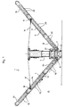
- FIG. 1 shows the device 1 according to the invention for clearing a heap 2, which essentially consists of the following components: a movable bridge 3 on rails, not shown, which cooperates with two rakes 4, 5, wherein only the rake 4 which is directly in engagement with the heap 2 can be actuated.
- the rakes 4, 5 are each pivoted about a horizontal axis 6, 7 in the lower region of the bridge 3.
- the pivoting movement is ensured in each case by cables 8, 9 which can be deflected in the upper region of the bridge 3 and which are firmly connected to the rake 4, 5, 10, 11.
- the rake 4, which is in engagement with the heap 2 in each case does not perform any relative movement transversely to the end face 12 of the heap.
- Each rake 4, 5 consists of a plurality of scratches 13, 14, 15, 16, 17, 18 arranged side by side, which are formed from a plurality of rotating scraper bars 19, 20 (see FIG. 2).
- the scraper bars 19, 20 move the material in Direction of the arrow continuously down the slope, where it is discharged sideways from the surrounding bridge scraper 21 connected to the bridge 3 at the base of the stockpile.
- FIG. 2 shows a plan view of the rake 4.
- the rake 4 consists of a frame which consists of welded square tubes 4 '.
- a plurality of scratches 13, 14, 15 arranged side by side are provided, which come to rest in different vertical planes on the end face 12 of the heap 2.
- Each scraper 13, 14, 15 is provided with a plurality of essentially horizontally extending scraper bars 19, which are firmly connected via plug-in drivers 22, each with a circumferential, wear-resistant round steel chain 23, 24.
- a divided drive shaft 25 is provided, which are connected via toothed couplings 26 to form a common drive shaft.
- Each shaft part 25 is additionally provided with the lower deflection wheels 27, 28 of the associated round link chain 23, 24.
- a drive 29, 30 is provided on each side of the shafts 25. This measure ensures that all the scratches 13-15 are operated together, the individual scraper bars 19 can continuously move the material down the slope.
- Figure 3 shows a schematic diagram of an alternative rake 31, which is also formed from a plurality of scratches 32-38 arranged in different vertical heights.
- the scraper irons 39 of the scratches 32-38 arranged next to one another are likewise held in laterally arranged circumferential round link chains 40, 41.
- the mutually facing end regions 42, 43 of each scraper 39 overlap one another in the horizontal direction, so that all regions of the stockpile 2 can be coated by the scraper 39.
- FIG. 4 represents a partial view of the coverage area.
Abstract
Description
Die Erfindung betrifft eine Einrichtung zum Räumen einer Halde gemäß den gattungsbildenden Merkmalen des ersten Patentanspruches.The invention relates to a device for clearing a heap according to the generic features of the first claim.
Durch die DE-A 30 21 308 ist eine Vorrichtung zum Räumen einer Halde mit einer in Längsrichtung der Halde verfahrbaren Brücke und einem von der Brücke getragenen zum Kratzeingriff mit der stirnseitigen Abbaufläche der Halde bestimmten Rechen bekannt. Der Rechen besitzt eine Form und Größe entsprechend der Abbaufläche der Halde. Der Rechen ist einerseits an zwei äußeren Punkten nahe seiner Basis und andererseits an wenigstens einem inneren im Bereich der vertikalen Mittelebene höher gelegenen Punkt mit der Brücke verbunden. Die zwischen dem Rechen und der Brücke vorgesehenen Verbindungen enthalten Antriebselemente, die dem Rechen in abgesenkter Lage eine böschungsabwärts gerichtete Kratzbewegung und in angehobener Lage eine böschungsaufwärts gerichtete Rückführbewegung erteilen.DE-A 30 21 308 discloses a device for clearing a heap with a bridge which can be moved in the longitudinal direction of the heap and a rake which is carried by the bridge and is intended for scratching engagement with the front-side mining surface of the heap. The rake has a shape and size corresponding to the mining area of the heap. The rake is connected on the one hand to the bridge at two outer points near its base and on the other hand at least one inner point located higher in the area of the vertical central plane. The connections provided between the rake and the bridge contain drive elements which give the rake a downward slope movement in the lowered position and a return movement upward slope in the raised position.
Durch diese Maßnahme soll insbesondere feuchtes oder gefrorenes Material, welches schlecht fließend ist, von der Böschungsspitze zum Böschungsfuß bewegt werden, wo es dann mittels seitlich austragender Einrichtungen, wie Brückenkratzer oder dgl., ausgetragen wird.This measure is intended, in particular, to move moist or frozen material which is poorly flowing from the tip of the embankment to the embankment foot, where it is then discharged by means of laterally discharging devices, such as bridge scrapers or the like.
Nachteilig an einer derartigen Konstruktion ist zu bemerken, daß der gesamte Rechen ständig in Bewegung gesetzt werden muß, um ein Herabrieseln des Materiales herbeizuführen. Da der Rechen in Abhängigkeit vom Haldenquerschnitt verhältnismäßig schwer ausfällt, sind hier dementsprechend ausgebildete Antriebselemente vonnöten. Infolge der ständigen Auf- und Abwärtsbewegung des Rechens findet hier eine inkonstante Fließbewegung des Materiales böschungsabwärts statt, da das Material nach Anheben und Aufwärtsbewegen des Rechens wieder zur Ruhe kommt und erst beim nächsten Eingriff der Kratzelemente weiter nach unten bewegt werden kann. Durch diese Maßnahme ist ein ebenfalls inkonstanter Materialtransport am Haldenfuß gegeben, so daß beim Austragen noch weitere Bunker oder dgl. als Zwischenspeicher vorgesehen werden müssen, um einen gleichmäßigen Materialaustrag zu gewährleisten.A disadvantage of such a construction is that the entire rake has to be constantly set in motion to cause the material to trickle down. Since the rake is relatively difficult depending on the stock cross-section, correspondingly designed drive elements are required here. As a result of the constant up and down movement of the rake, there is an inconsistent flow of material down the slope, since the material comes to rest after lifting and moving the rake up and can only be moved further down the next time the scraper elements engage. This measure also results in inconsistent material transport at the base of the stockpile, so that further bunkers or the like must be provided as intermediate stores during discharge in order to ensure uniform material discharge.
Die gattungsgemäße SU-A 174 644 betrifft ein Haldenräumgerät, das mit einem stationären Rechen ausgerüstet ist, in dessen unterem Bereich mehrere nebeneinander angeordnete Kratzer vorgesehen sind, die das im oberen Bereich der Halde durch den Rechen gelöste Material böschungsabwärts bewegen. Der Antrieb ist hierbei alternierend ausgelegt. Nachteilig ist festzustellen, daß eine derartige Einrichtung nicht in der Lage ist, zur Brückenbildung neigendes Material kontinuierlich auszutragen, zumal die Brückenbildung auf der gesamten abzubauenden Stirnfläche stattfindet und der stationäre - zwar seitlich bewegbar Rechen - nicht in der Lage ist, ausreichend Material zu lösen, um auf diese Art und Weise eine hinreichende Materialzufuhr in den Bereich der Kratzer zu gewährleisten.The generic SU-A 174 644 relates to a heap clearing device which is equipped with a stationary rake, in the lower area of which several scratches are provided which move the material loosened by the rake in the upper area of the heap down the slope. The drive is designed alternately. It is disadvantageous to note that such a device is not able to continuously discharge material that tends to form bridges, especially since the bridging takes place on the entire front surface to be dismantled and the stationary rake - although laterally movable - is not able to solve sufficient material, in order to ensure a sufficient supply of material in the area of the scratches in this way.
Der Erfindung liegt ausgehend vom gattungsbildenden Teil des ersten Anspruches die Aufgabe zugrunde, die hier beschriebene Einrichtung dahingehend weiterzubilden, daß insbesondere zum Kleben neigendes, schwerfließendes, schüttfähiges Material einerseits problemlos böschungsabwärts transportiert und daß andererseits ein konstanter Materialaustrag ohne nachgeschaltete Bunker oder dgl. realisiert werden kann.Starting from the generic part of the first claim, the invention is based on the object of developing the device described here in such a way that, in particular, sticky, poorly flowing, pourable material can be easily transported down the slope and, on the other hand, a constant material discharge can be achieved without a downstream bunker or the like .
Diese Aufgabe wird erfindungsgemäß dadurch gelöst, daß der die Kratzer beinhaltende und die Abbaufläche im wesentlichen überdeckende Rahmen während des Verfahrens der Brücke stationär an der stirnseitigen Abbaufläche der Halde ruht und daß jeder Kratzer aus mehreren, jeweils zwischen zwei umlaufenden Zugelementen angeordneten als Kratzeisen ausgebildeten umlaufenden Kratzelementen besteht.This object is achieved in that the frame containing the scratches and essentially covering the excavation surface rests stationary during the movement of the bridge on the front surface of the stockpile and that each scratch consists of a plurality of circumferential scraping elements, each arranged between two rotating traction elements, designed as scraping irons consists.
Durch diese Ausbildung wird sichergestellt, daß selbst zum Kleben neigendes Material problemlos böschungsabwärts bewegt werden kann, und zwar in kontinuierlichem Massenfluß und auf der gesamten Haldenbreite. Infolge dieses kontinuierlichen Massenflusses, über die gesamte Breite der Halde gesehen, erfolgt eine gute Homogenisierung des Materiales sowie eine gute Schaufelfüllung des seitlich austragenden Organes (Brückenkratzer oder dgl.).This design ensures that even material that tends to stick can be easily moved down the slope, in a continuous mass flow and over the entire pile width. As a result of this continuous mass flow, seen over the entire width of the heap, there is a good homogenization of the material and a good scoop filling of the laterally discharging organ (bridge scraper or the like).
Jeder Kratzer ist vorzugsweise aus einer Vielzahl seitlich an umlaufenden Zugelementen, wie Seilen, Gummigurten, Ketten oder dgl. verlagerten Kratzeisen gebildet, die das Material böschungsabwärts transportieren. Die Kratzeisen können hierbei entweder geradlinig oder aber gewölbt ausgebildet werden. Die spezielle Art der Ausbildung sollte hierbei vom zu räumenden Material abhängig gemacht werden.Each scratch is preferably formed from a plurality of laterally displaced scraping elements, such as ropes, rubber belts, chains or the like. Scraper irons which transport the material downstream of the slope. The Scraper irons can either be straight or curved. The special type of training should be made dependent on the material to be cleared.
Bei Verwendung von Ketten sind diese, einem weiteren Gedanken der Erfindung gemäß, als Rundstahlketten ausgebildet, die im Bereich des Untertrums auf der der Halde zugewandten Seite in verschleißarmen Lagern geführt sind. Die Auswahl der Materialien (z.B. Stahl auf Stahl, Kunststoff auf Stahl, usw.) hängt hierbei vom jeweiligen zu räumenden Material ab.If chains are used, according to a further idea of the invention, they are designed as round steel chains which are guided in low-wear bearings in the area of the lower run on the side facing the heap. The choice of materials (e.g. steel on steel, plastic on steel, etc.) depends on the material to be cleared.
Damit jeder Bereich der Haldenstirnfläche erreicht werden kann, wird weiterhin vorgeschlagen, die Kratzeisen benachbarter Kratzer so in ihrer Länge auszubilden, daß deren Endbereiche einander überdecken.So that every area of the stockpile end face can be reached, it is further proposed to design the scraping irons of adjacent scratches in such a length that their end areas overlap one another.
Wie bereits angesprochen, ist der gemeinsame Antrieb für die einzelnen Kratzer im unteren Bereich des Rechens vorgesehen. Der Antrieb wird vorzugsweise durch zwei Einzelantriebe gebildet, von denen jeweils einer am freien Ende einer durch Kupplungen unterteilten Antriebswelle angeordnet ist. Die Antriebswelle ist aus dem Grund unterteilt, damit Wartungsarbeiten bzw. Reparaturen im Bereich der einzelnen Kratzer, der Antriebsketten sowie weiterer peripherer Bauteile problemlos durchgeführt werden können. Um Schlupf in den einzelnen Kettensträngen zu vermeiden, sind die Wellen in Stehlagern mit Pendelrollenlagern verlagert und mit Zahnkupplungen untereinander verbunden. Somit bleibt der jeweilige Abstand, in vertikaler Richtung gesehen, zwischen den einander überdeckenden Kratzeisen ständig gewahrt und eine Berührung der Kratzeisen benachbarter Kratzer wird ausgeschlossen.As already mentioned, the common drive for the individual scratches is provided in the lower area of the rake. The drive is preferably formed by two individual drives, one of which is arranged at the free end of a drive shaft divided by couplings. The drive shaft is divided for the reason that maintenance work or repairs in the area of the individual scratches, the drive chains and further peripheral components can be carried out without any problems. In order to avoid slippage in the individual chain strands, the shafts are moved in pillow block bearings with spherical roller bearings and connected to one another with toothed couplings. Thus, the respective distance, seen in the vertical direction, between the overlapping scraper bars is constantly maintained and touching the scraper bars of adjacent scratches is excluded.
Die Erfindung ist anhand eines Ausführungsbeispieles in der Zeichnung dargestellt und wird wie folgt beschrieben. Es zeigen:
- Figur 1 -
- Seitenansicht der erfindungsgemäßen Einrichtung zum Räumen einer Halde
- Figur 2 -
- Draufsicht auf einen der Rechen samt Kratzereinrichtungen
- Figur 3 -
- Prinzipskizze einer alternativen Rechenhälfte mit Überdeckung der Kratzeisen
- Figur 4 -
- Teilansicht eines Überdeckungsbereiches gem.
Figur 3
- Figure 1 -
- Side view of the inventive device for clearing a heap
- Figure 2 -
- Top view of one of the rakes and scratching devices
- Figure 3 -
- Schematic diagram of an alternative half of the rake with covering of the scraper
- Figure 4 -
- Partial view of a coverage area acc. Figure 3
Figur 1 zeigt die erfindungsgemäße Einrichtung 1 zum Räumen einer Halde 2, die im wesentlichen aus folgenden Bauteilen besteht:
einer auf nicht weiter dargestellten Schienen verfahrbaren Brücke 3, die mit zwei Rechen 4,5 zusammenwirkt, wobei lediglich der jeweils unmittelbar im Eingriff mit der Halde 2 stehende Rechen 4 betätigbar ist. Die Rechen 4,5 sind jeweils um eine Horizontalachse 6,7 schwenkbar im unteren Bereich der Brücke 3 verlagert. Die Schwenkbewegung wird jeweils über im oberen Bereich der Brücke 3 umlenkbare Seile 8,9 sichergestellt, die mit dem Rechen 4,5 fest verbunden sind 10,11. Der jeweils mit der Halde 2 in Eingriff stehende Rechen 4 führt keine Relativbewegung quer zur Haldenstirnfläche 12 durch. Jeder Rechen 4,5 besteht aus mehreren nebeneinander angeordneten Kratzern 13,14,15,16,17,18, die aus einer Vielzahl umlaufender Kratzeisen 19,20 gebildet sind (siehe Figur 2).. Die Kratzeisen 19,20 bewegen das Material in Pfeilrichtung kontinuierlich böschungsabwärts, wo es von mit der Brücke 3 verbundenen umlaufenden Brückenkratzern 21 am Haldenfuß seitwärts ausgetragen wird.FIG. 1 shows the device 1 according to the invention for clearing a
a
Figur 2 zeigt eine Draufsicht auf den Rechen 4. Der Rechen 4 besteht aus einem Rahmen, der aus zusammengeschweißten Vierkantrohren 4' besteht. Im Bereich des Rahmens sind mehrere nebeneinander angeordnete Kratzer 13,14,15 vorgesehen, die in unterschiedlichen vertikalen Ebenen an der Stirnfläche 12 der Halde 2 zur Anlage kommen. Jeder Kratzer 13,14,15 ist mit einer Vielzahl im wesentlichen horizontal sich erstreckender Kratzeisen 19 versehen, die über Steckmitnehmer 22 mit jeweils einer umlaufenden verschleißfesten Rundstahlkette 23,24 fest verbunden sind. Im unteren Bereich des Rechens 4 bzw. des Rahmens 4' ist eine geteilte Antriebswelle 25 vorgesehen, die über Zahnkupplungen 26 zu einer gemeinschaftlichen Antriebswelle verbunden werden. Jeder Wellenteil 25 ist zusätzlich mit den unteren Umlenkrädern 27,28 der zugehörigen Rundgliederkette 23,24 versehen. Beiderseits der Wellen 25 ist jeweils ein Antrieb 29,30 vorgesehen. Durch diese Maßnahme wird eine gemeinsame Betätigung sämtlicher Kratzer 13-15 gewährleistet, wobei die einzelnen Kratzeisen 19 das Material in kontinuierlicher Weise böschungsabwärts bewegen können.Figure 2 shows a plan view of the
Figur 3 zeigt eine Prinzipskizze eines alternativen Rechens 31, der ebenfalls aus mehreren in verschiedenen vertikalen Höhen angeordneten Kratzern 32-38 gebildet ist. Die Kratzeisen 39 der nebeneinander angeordneten Kratzer 32-38 sind ebenfalls in seitlich angeordneten umlaufenden Rundgliederketten 40,41 gehalten. Die einander zugewandten Endbereiche 42,43 eines jeden Kratzeisens 39 überdecken einander in horizontaler Richtung, so daß sämtliche Bereiche der Halde 2 durch die Kratzeisen 39 bestrichen werden können.Figure 3 shows a schematic diagram of an alternative rake 31, which is also formed from a plurality of scratches 32-38 arranged in different vertical heights. The
Diese Maßgabe wird in Figur 4 noch einmal verdeutlicht, die eine Teilansicht des Überdeckungsbereiches darstellt.This requirement is clarified again in FIG. 4, which represents a partial view of the coverage area.
Claims (5)
- Device for removing material from a stockpile (2), with a bridge (3) that is movable in the longitudinal direction of the stockpile (2) and also a plurality of scrapers (13-18, 32-38) which are arranged adjacent to one another in the region of a frame connected to the bridge (3), are equipped with scraper members (19, 20, 39), and are at different heights, and which are pivotable about a horizontal axis (6, 7), the scrapers (13-18, 32-38) being arranged to be driven together, characterised in that the frame (4') which contains the scrapers (13-18, 32-38) and substantially covers the extraction face (12) remains stationary on the front extraction face (12) of the stockpile (2) while the bridge (3) is travelling, and that each scraper (13-18, 32-38) consists of a plurality of rotating scraper members in the form of scraper blades (19, 20, 39), each arranged between two rotating traction elements (23, 24, 40, 41).
- Device according to Claim 1, characterised in that the traction elements (23, 24, 40, 41) are formed of cables, rubber belts or chains.
- Device according to Claims 1 and 2, characterised in that when using chains (23, 24, 40, 41) the latter are in the form of round steel chains which in the region of the lower portion on the side facing the stockpile (2) are guided in profiles of plastics material.
- Device according to Claims 1 to 3, characterised in that the ends (42, 43) of the scraper blades (19, 20, 39) of adjacent scrapers (13-18, 32-38) overlap in a horizontal direction.
- Device according to Claims 1 to 4, characterised in that in the lower region of the frame (4, 31) on each side of the ends of a drive shaft (25) divided by clutches (26), especially toothed clutches, a drive (29, 30) is provided.
Priority Applications (1)
| Application Number | Priority Date | Filing Date | Title |
|---|---|---|---|
| AT90100821T ATE92428T1 (en) | 1989-02-24 | 1990-01-16 | EQUIPMENT FOR CLEARING A STACK. |
Applications Claiming Priority (2)
| Application Number | Priority Date | Filing Date | Title |
|---|---|---|---|
| DE3905670A DE3905670C1 (en) | 1989-02-24 | 1989-02-24 | |
| DE3905670 | 1989-02-24 |
Publications (2)
| Publication Number | Publication Date |
|---|---|
| EP0384118A1 EP0384118A1 (en) | 1990-08-29 |
| EP0384118B1 true EP0384118B1 (en) | 1993-08-04 |
Family
ID=6374790
Family Applications (1)
| Application Number | Title | Priority Date | Filing Date |
|---|---|---|---|
| EP90100821A Expired - Lifetime EP0384118B1 (en) | 1989-02-24 | 1990-01-16 | Device for removing material from a stock pile |
Country Status (3)
| Country | Link |
|---|---|
| EP (1) | EP0384118B1 (en) |
| AT (1) | ATE92428T1 (en) |
| DE (3) | DE8902185U1 (en) |
Families Citing this family (4)
| Publication number | Priority date | Publication date | Assignee | Title |
|---|---|---|---|---|
| DE4402130C1 (en) * | 1994-01-21 | 1995-05-04 | Ver Energiewerke Ag | Method and appliance for conveying away a heap of biomass, especially a heap of wood chips |
| CN103318605A (en) * | 2013-06-03 | 2013-09-25 | 嘉兴市一建机械制造有限公司 | Scraping plate material taking machine |
| CN103318606A (en) * | 2013-06-03 | 2013-09-25 | 嘉兴市一建机械制造有限公司 | Scraping plate device |
| CN114772306A (en) * | 2022-03-21 | 2022-07-22 | 中国中材国际工程股份有限公司 | Bridge type scraper reclaimer for reclaiming sticky wet material end face |
Family Cites Families (4)
| Publication number | Priority date | Publication date | Assignee | Title |
|---|---|---|---|---|
| DE2314849A1 (en) * | 1973-03-24 | 1974-09-26 | Pohlig Heckel Bleichert | RAKE FOR A SHEET RECEIVER |
| GB1383280A (en) * | 1973-07-18 | 1974-02-12 | Caterpillar Tractor Co | Self-loading scrapers |
| DE3021308A1 (en) * | 1980-06-06 | 1982-01-07 | Krupp Polysius Ag, 4720 Beckum | Dump heap reclaiming installation - has bridge mounted rake with connectors contg. drive elements, imparting downward scraping and upward return motions |
| DE3219185C2 (en) * | 1982-05-21 | 1986-05-07 | Gustav Schade Maschinenfabrik Gmbh & Co, 4600 Dortmund | Bridge device for clearing heaps of bulk material |
-
1989
- 1989-02-24 DE DE8902185U patent/DE8902185U1/de not_active Expired - Lifetime
- 1989-02-24 DE DE3905670A patent/DE3905670C1/de not_active Expired - Lifetime
-
1990
- 1990-01-16 DE DE9090100821T patent/DE59002134D1/en not_active Expired - Fee Related
- 1990-01-16 EP EP90100821A patent/EP0384118B1/en not_active Expired - Lifetime
- 1990-01-16 AT AT90100821T patent/ATE92428T1/en not_active IP Right Cessation
Also Published As
| Publication number | Publication date |
|---|---|
| EP0384118A1 (en) | 1990-08-29 |
| DE59002134D1 (en) | 1993-09-09 |
| ATE92428T1 (en) | 1993-08-15 |
| DE3905670C1 (en) | 1990-05-10 |
| DE8902185U1 (en) | 1990-06-28 |
Similar Documents
| Publication | Publication Date | Title |
|---|---|---|
| DE3424668A1 (en) | TRACK CONSTRUCTION MACHINE, IN PARTICULAR BOTTLE BED CLEANING MACHINE WITH SCREENING SYSTEM | |
| DE2057197B2 (en) | Mobile machine for picking up, cleaning and reintroducing ballast ballast from railway tracks | |
| EP0384118B1 (en) | Device for removing material from a stock pile | |
| DD202059A5 (en) | RUNNING PLANT FOR MANUFACTURING A PROTECTIVE LAYER BETWEEN PLANUM AND PITCH BED | |
| EP0480075B1 (en) | Conveying sieve grid | |
| DE2907966A1 (en) | HALDENRAEUMGERAET | |
| DE2461756C3 (en) | Conveyor device for bulk goods from a storage dump | |
| DE2610658C3 (en) | Silo system, especially for clay and clay-like masses | |
| DE1904578A1 (en) | Chain conveyor | |
| DE2927256A1 (en) | TRACK SLEEVE REPLACEMENT DEVICE WITH BALK BED LOWERING AND LEVELING DEVICE | |
| DE10304984B4 (en) | Cleaning device for plate belt conveyor | |
| DE3800605A1 (en) | Installation for erecting and removing heaps in blending plants | |
| EP0038554A1 (en) | Grid to sieve and sort particulate matter | |
| DE19529235C2 (en) | Device for producing a spoil tip in surface mining and its use | |
| DE3021308A1 (en) | Dump heap reclaiming installation - has bridge mounted rake with connectors contg. drive elements, imparting downward scraping and upward return motions | |
| AT241360B (en) | Trash rack cleaning machine | |
| DE1958847A1 (en) | Conveyor system for the continuous removal of bulk goods | |
| AT373938B (en) | SNOWROOM UNIT | |
| DE1068179B (en) | ||
| DE3223372A1 (en) | Breeze conveyor | |
| DE3205741A1 (en) | Device for unloading bulk material from a bulk material store | |
| DE2240111A1 (en) | DEVICE FOR CONTINUOUS REMOVAL OF A HUMPED HOPE BY MEANS OF A HOPE-CLEARING DEVICE TRANSVERSE TO THE HOPE | |
| DD155626A1 (en) | RAIL-CONTAINED TRANSPORT CAR FOR SCHUETTGUETER | |
| DE3724375A1 (en) | Discharge device, in particular for scraper conveyor devices and bucket conveyors | |
| DE202004019799U1 (en) | Equipment extracting bulk organic matter from composting tunnel, locates conveyor between reciprocating floor and drive unit |
Legal Events
| Date | Code | Title | Description |
|---|---|---|---|
| PUAI | Public reference made under article 153(3) epc to a published international application that has entered the european phase |
Free format text: ORIGINAL CODE: 0009012 |
|
| AK | Designated contracting states |
Kind code of ref document: A1 Designated state(s): AT BE DE FR GB |
|
| 17P | Request for examination filed |
Effective date: 19900911 |
|
| RIN1 | Information on inventor provided before grant (corrected) |
Inventor name: DECKARM, KURT Inventor name: BODE, GUENTER |
|
| 17Q | First examination report despatched |
Effective date: 19920406 |
|
| GRAA | (expected) grant |
Free format text: ORIGINAL CODE: 0009210 |
|
| AK | Designated contracting states |
Kind code of ref document: B1 Designated state(s): AT BE DE FR GB |
|
| REF | Corresponds to: |
Ref document number: 92428 Country of ref document: AT Date of ref document: 19930815 Kind code of ref document: T |
|
| REF | Corresponds to: |
Ref document number: 59002134 Country of ref document: DE Date of ref document: 19930909 |
|
| RAP2 | Party data changed (patent owner data changed or rights of a patent transferred) |
Owner name: PWH ANLAGEN + SYSTEME GMBH |
|
| ET | Fr: translation filed | ||
| GBT | Gb: translation of ep patent filed (gb section 77(6)(a)/1977) |
Effective date: 19931112 |
|
| PLBE | No opposition filed within time limit |
Free format text: ORIGINAL CODE: 0009261 |
|
| STAA | Information on the status of an ep patent application or granted ep patent |
Free format text: STATUS: NO OPPOSITION FILED WITHIN TIME LIMIT |
|
| 26N | No opposition filed | ||
| PGFP | Annual fee paid to national office [announced via postgrant information from national office to epo] |
Ref country code: GB Payment date: 19951214 Year of fee payment: 7 |
|
| PGFP | Annual fee paid to national office [announced via postgrant information from national office to epo] |
Ref country code: BE Payment date: 19951215 Year of fee payment: 7 |
|
| PGFP | Annual fee paid to national office [announced via postgrant information from national office to epo] |
Ref country code: FR Payment date: 19951219 Year of fee payment: 7 |
|
| PGFP | Annual fee paid to national office [announced via postgrant information from national office to epo] |
Ref country code: AT Payment date: 19951221 Year of fee payment: 7 |
|
| PGFP | Annual fee paid to national office [announced via postgrant information from national office to epo] |
Ref country code: DE Payment date: 19951223 Year of fee payment: 7 |
|
| PG25 | Lapsed in a contracting state [announced via postgrant information from national office to epo] |
Ref country code: GB Effective date: 19970116 Ref country code: AT Effective date: 19970116 |
|
| PG25 | Lapsed in a contracting state [announced via postgrant information from national office to epo] |
Ref country code: BE Effective date: 19970131 |
|
| BERE | Be: lapsed |
Owner name: ORENSTEIN & KOPPEL A.G. O&K Effective date: 19970131 |
|
| GBPC | Gb: european patent ceased through non-payment of renewal fee |
Effective date: 19970116 |
|
| PG25 | Lapsed in a contracting state [announced via postgrant information from national office to epo] |
Ref country code: FR Effective date: 19970930 |
|
| PG25 | Lapsed in a contracting state [announced via postgrant information from national office to epo] |
Ref country code: DE Effective date: 19971001 |
|
| REG | Reference to a national code |
Ref country code: FR Ref legal event code: ST |