EP0382243A2 - Optisches Übertragungsleitungssystem - Google Patents
Optisches Übertragungsleitungssystem Download PDFInfo
- Publication number
- EP0382243A2 EP0382243A2 EP90102582A EP90102582A EP0382243A2 EP 0382243 A2 EP0382243 A2 EP 0382243A2 EP 90102582 A EP90102582 A EP 90102582A EP 90102582 A EP90102582 A EP 90102582A EP 0382243 A2 EP0382243 A2 EP 0382243A2
- Authority
- EP
- European Patent Office
- Prior art keywords
- bits
- transmission line
- optical transmission
- signal
- optical
- Prior art date
- Legal status (The legal status is an assumption and is not a legal conclusion. Google has not performed a legal analysis and makes no representation as to the accuracy of the status listed.)
- Ceased
Links
Images


Classifications
-
- H—ELECTRICITY
- H04—ELECTRIC COMMUNICATION TECHNIQUE
- H04B—TRANSMISSION
- H04B10/00—Transmission systems employing electromagnetic waves other than radio-waves, e.g. infrared, visible or ultraviolet light, or employing corpuscular radiation, e.g. quantum communication
- H04B10/07—Arrangements for monitoring or testing transmission systems; Arrangements for fault measurement of transmission systems
- H04B10/075—Arrangements for monitoring or testing transmission systems; Arrangements for fault measurement of transmission systems using an in-service signal
- H04B10/077—Arrangements for monitoring or testing transmission systems; Arrangements for fault measurement of transmission systems using an in-service signal using a supervisory or additional signal
-
- H—ELECTRICITY
- H04—ELECTRIC COMMUNICATION TECHNIQUE
- H04B—TRANSMISSION
- H04B10/00—Transmission systems employing electromagnetic waves other than radio-waves, e.g. infrared, visible or ultraviolet light, or employing corpuscular radiation, e.g. quantum communication
- H04B10/07—Arrangements for monitoring or testing transmission systems; Arrangements for fault measurement of transmission systems
- H04B10/075—Arrangements for monitoring or testing transmission systems; Arrangements for fault measurement of transmission systems using an in-service signal
- H04B10/079—Arrangements for monitoring or testing transmission systems; Arrangements for fault measurement of transmission systems using an in-service signal using measurements of the data signal
- H04B10/0795—Performance monitoring; Measurement of transmission parameters
- H04B10/07955—Monitoring or measuring power
-
- H—ELECTRICITY
- H04—ELECTRIC COMMUNICATION TECHNIQUE
- H04B—TRANSMISSION
- H04B10/00—Transmission systems employing electromagnetic waves other than radio-waves, e.g. infrared, visible or ultraviolet light, or employing corpuscular radiation, e.g. quantum communication
- H04B10/50—Transmitters
- H04B10/501—Structural aspects
- H04B10/503—Laser transmitters
-
- H—ELECTRICITY
- H04—ELECTRIC COMMUNICATION TECHNIQUE
- H04B—TRANSMISSION
- H04B10/00—Transmission systems employing electromagnetic waves other than radio-waves, e.g. infrared, visible or ultraviolet light, or employing corpuscular radiation, e.g. quantum communication
- H04B10/50—Transmitters
- H04B10/564—Power control
-
- H—ELECTRICITY
- H04—ELECTRIC COMMUNICATION TECHNIQUE
- H04B—TRANSMISSION
- H04B2210/00—Indexing scheme relating to optical transmission systems
- H04B2210/07—Monitoring an optical transmission system using a supervisory signal
- H04B2210/072—Monitoring an optical transmission system using a supervisory signal using an overhead signal
-
- H—ELECTRICITY
- H04—ELECTRIC COMMUNICATION TECHNIQUE
- H04B—TRANSMISSION
- H04B2210/00—Indexing scheme relating to optical transmission systems
- H04B2210/08—Shut-down or eye-safety
Definitions
- the present invention relates to an optical transmission line system, more particularly to an optical transmission line system using laser light.
- the laser light emitted from the point of disconnection, etc. may leak out and harm the eyes of the system maintenance personnel. Some measures are required to prevent this.
- optical transmission line systems for example, optical transmission line systems constituted by a first telephone exchange office, a second telephone exchange office, and an optical transmission line connecting these telephone exchange offices, have been constructed as follows. Provision is made of a first optical transmission line equipment and second optical transmission line equipment which perform the transmission and reception of downstream transmission signals and upstream transmission signals through a downstream optical transmission line and an upstream optical transmission line. Further, the first and second optical transmission line equipment include first and second optical signal transmission units, first and second optical signal reception units, and first and second light stoppage detecting means provided at the input stages of the first and second optical signal reception units.
- the stoppage of the received light signal will be detected at the first light stoppage detecting means in the first optical transmission line equipment.
- the operation of the corresponding first optical signal transmission unit will be stopped by the received light signal stoppage detecting signal and the transmission of the optical transmission signal to the downstream optical transmission line will be suspended.
- the second light stoppage detecting means in the second optical transmission line equipment on the other side will output a received light signal stoppage detecting signal too.
- This received light signal stoppage detecting signal is applied to the corresponding second optical signal transmission unit to stop the drive of the second optical signal transmission unit. That is, the transmission of the optical transmission signal from the second optical signal transmission unit to the upstream optical transmission line is suspended. Therefore, the laser light leaking from the location of the disconnection or other breakage in the middle of the upstream optical transmission line disappears. Thus, it is possible to prevent damage to the eyes of the systems maintenance personnel who rush to the location of that disconnection or other breakage.
- the optical transmission line system stops transmitting and receiving completely despite the fact that there is no disconnection in the other optical transmission line (downstream) and it is normal.
- the complete cessation of transmission and reception in this way is a problem in that it ends up lowering the working efficiency of the optical transmission line system.
- the present invention has as its object to provide an optical transmission line system which can maintain the working efficiency at a certain high level even with disconnection, etc. of the optical transmission line.
- the present invention newly introduces a light transmission level reducing means which, when stoppage of the received light signal is detected by the above-mentioned light stoppage detecting means, reduces to a level harmless to the human eye the transmission level of the light transmission signal from the optical signal transmission unit provided inside the optical transmission line equipment in which the light stoppage detecting means is provided.
- the reception side in the optical transmission line equipment there is introduced a means for detecting, apart from the light signal stoppage, the reduction of the level of the received light signal.
- the above-mentioned light transmission level reducing means is activated when either the detecting signal from the level reduction detecting means or the above-mentioned received light signal stoppage detecting signal is generated.
- the above-mentioned light transmission level reducing means makes "0" all the main signal data bits in the light transmission signal, which is constituted of main signal data bits and a small number of bits of supervisory information, and thereby reduces the average light transmission level.
- the supervisory information bits are small in number, so even if all the supervisory information bits were to become "1" (when light is generated), the intensity of the light would not be irritating in any way to the eye of the maintenance personnel. In this way, even if disconnection or other breakage of the optical transmission line occurs, the supervisory information can be sent to the optical transmission line equipment on the other side and the working efficiency of the optical transmission line system can be vastly improved compared with the situation in the past when disconnection or other breakage occurred.
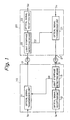
- Figure 1 is a block diagram of the constitution of the principle of a conventional optical transmission line system.
- the conventional optical transmission line system shown in the figure is provided with a first optical transmission line equipment 10 and second optical transmission line equipment 20 which perform the transmission and reception of downstream transmission signals Sd and upstream transmission signals Su through a downstream optical transmission line 17 and an upstream optical transmission line 27, and the first and second optical transmission line equipment 10 and 20 include first and second optical signal transmission units 11 and 21, first and second optical signal reception units 12 and 22, and first and second light stoppage detecting means 13 and 23 provided at the input stages of the first and second optical signal reception units.
- the stoppage of the received light signal is detected at the first light stoppage detecting means 13 in the first optical transmission line equipment 10.
- the operation of the corresponding first optical signal transmission unit 11 will be stopped by the received light signal stoppage detecting signal D1 and the transmission of the light transmission signal to the downstream optical transmission line 17 will be suspended.
- the second light stoppage detecting means 23 in the second optical transmission line equipment 20 on the other side will output a received light signal stoppage detecting signal D2 too.
- This received light signal stoppage detecting signal D2 is applied to the corresponding second optical signal transmission unit 21 to stop the drive of the second optical signal transmission unit 21.
- the transmission of the light transmission signal from the second optical signal transmission unit 21 to the upstream optical transmission line 27 is suspended. Therefore, the laser light leaking from the location of the disconnection or other breakage (x mark) in the middle of the upstream optical transmission line 27 disappears. Thus, it is possible to prevent damage to the eyes of the systems maintenance personnel who rush to the location of that disconnection or other breakage.
- FIG. 2 is a circuit diagram of the specific construction of a conventional optical transmission line system. Note that throughout the figures, the same component elements are given the same reference numerals or symbols.
- the downstream transmission signals Sd are received by a bipolar/unipolar converting circuit (B/U) 112 which serves as an interface, supervisory information (SV) collected at one's own office (10) is inserted into the predetermined service bits, for example, overhead bits (O/H), in the six bits by the 5B/6B coding circuit 111′, the main signal data bits and supervisory information bits are converted to laser light by an optical transmission circuit (OT), and the light is sent to the optical transmission line equipment 20 through the optical transmission line 17.
- the main signal data bits are divided into units of five bits and the five bits of each unit are converted into six bits of data (three "1"s and three "0"s) with a mark ratio of 50 percent.
- the downstream transmission signal (laser light signal) from the optical transmission line equipment 10 is received at an optical reception circuit (OR) 223 and converted into electrical signals.
- the supervisory information in the O/H bits are taken out by the 5B/6B decoding circuit 221′, then the downstream transmission signal Sd is transmitted from the unipolar/bipolar converting circuit 222 serving as an interface.
- the transmission of data from the optical transmission line equipment 20 to the optical transmission line equipment 10 is performed in exactly the same way as above.
- the component elements (212, 211, 213, 123, 121, and 122) performing this upstream side data transmission are completely equivalent to the component elements performing this upstream side data transmission.
- Figure 3 is a format diagram of a transmission signal used in a 5B/6B conversion type optical transmission line system. As shown in column (a) of the figure, six bits are used as one word (WD) and 18 words as one subframe. One bit of a service bit (O/H) is provided in one subframe. As shown in the column (b), 12 of the service bits, that is, 12 subframes worth, are collected. By this, it is possible to form the supervisory information shown in column (c).
- the light stoppage detection means 13 in the optical reception circuit (OR) 123 of the optical transmission line equipment 10 detect the stoppage of the received light, controls the optical transmission circuit (OT) 113, and prevents laser light from being sent to the transmission 17.
- the light stoppage detecting means 23 provided in the optical circuit (OR) 223 of the optical transmission line equipment 20 detects the stoppage of the received light signal and performs control to prevent the laser light from being sent to the upstream optical transmission line 27. As a result, there is no longer any leakage of laser light from the disconnected or broken location (x).
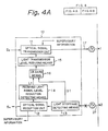
- Figures 4A and 4B are a block diagram of the constitution of the principle of an optical transmission line system based on the present invention. There are the following differences from the conventional optical transmission line system (Fig. 1).
- first and second optical signal transmission units 11 and 21 are further provided with first and second light transmission level reducing means 15 and 25 which cooperate with each other.
- the first and second light transmission level reducing means 15 and 25 are driven when the first and second light stoppage detecting means 13 and 23 detect stoppage of the received light signals and reduce the transmission level of the light transmission signals from the first and second optical signal transmission units 11 and 21 to a level harmless to the human eye.
- first and second optical signal reception units 12 and 22 are provided with first and second received light signal level reduction detecting means 14 and 24 which cooperate with each other and defect if the level of the received light signals is much lower than the usual received level.
- first and second OR gate means 16 and 26 are provided.
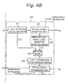
- the first OR gate means 16 receives as input the first received light signal stoppage detecting signal D1 from the first light stoppage detecting means 13 or the first level reduction detecting signal L1 from the first received light signal level reduction detecting means 14 and, where either of the detecting signals D1 or L1 is generated, drives the first light transmission level reducing means 15.
- the second OR gate means 26 receives as input the second received light signal stoppage detecting signal D2 from the second light stoppage detecting means 23 or the second level reduction detecting signal L2 from the second received light signal level reduction detecting means 24 and, where either of the detecting signals D2 or L2 is generated, drives the second light transmission level reducing means 25.
- the first light transmission level reducing means 15 makes "0" all of the downstream main signal data bits of the downstream main signal data bits and the small number of downstream supervisory information bits composing the light transmission signal sent to the downstream optical transmission line 17.
- the second light transmission level reducing means 25 makes "0" all of the upstream main signal data bits of the upstream main signal data bits and the small number of upstream supervisory information bits composing the light transmission signal sent to the upstream optical transmission line 27.
- downstream or upstream supervisory information bits are transmitted from the optical transmission line equipment 10 of the transmission side to the optical transmission line equipment 20 of the reception side. Only the supervisory information is made usable in the system even after the occurrence of a disconnection or other breakage of the transmission line.
- the first is that when the above-mentioned disconnection occurs, the optical transmission line system cannot immediately judge where that disconnection occurred. That is, the first light stoppage detecting means 13 detects the stoppage of the received light signal, but cannot immediately determine that the stoppage was caused in the middle of the upstream optical transmission line 27. The reason is that even if the disconnection occurred in the middle of the downstream optical transmission line 17, the first light stoppage detecting means 13 would similarly detect stoppage of the received light signal. That is, just because the stoppage of the received light signal is detected by the upstream side first light stoppage detecting means 13, there is no guarantee that the downstream optical transmission line 17 is normal.
- the second is related to the first answer.
- the disconnection of the optical transmission line may not occur just in one of the upstream and downstream optical transmission lines. In some cases, it may occur simultaneously in both of the upstream and downstream optical transmission lines 17 and 27. In such a case, both the first and second optical signal transmission units 11 and 21 must simultaneously reduce the light transmission levels, or else it will not be possible to protect the eyes of the systems maintenance personnel hurrying to the locations of the two disconnections. In such cases, however, the system is completely shut down.
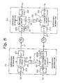
- Figure 5 is a block diagram of the specific construction of the optical transmission line system of the present invention. This corresponds to the specific construction shown in Fig. 2.
- the first OR gate 161 and the second OR gate 261 in Fig. 5 correspond to the first and second OR gate means 16 and 26 in Fig. 4.
- the first and second coding circuits 111 and 211 in Fig. 5 include the first and second light transmission level reducing means 15 and 25, respectively, so differ slightly in construction from the first and second coding circuits 111′ and 211′ shown in Fig. 2.
- the first and second decoding circuits 121 and 221 of Fig. 5 include the first and second received light signal level reduction detecting means 14 and 24, respectively, so differ slightly in construction from the first and second decoding circuits 121′ and 221′ of Fig. 2.
- the light stoppage detecting means 13 in the optical transmission line (OR) 123 issues a stoppage detecting signal D1 of the received light signal or the decoding circuit 121 fetches the supervisory information composed of the service bits (O/H) and issues an all "0" detecting signal of the main signal data bits remaining after elimination of the supervisory information, that is, the received light signal level reduction detecting signal L1, from the level reduction detecting means 14.
- the means 15 in the coding circuit 111 receives through the OR gate 161 the stoppage detecting signal D1 or the all "0" detecting signal L1, it changes the main signal data bits remaining after elimination of the supervisory information bits to all "0" and sends out the same.
- the means 13 provided in the optical reception circuit (OR) 123 of the first optical transmission line equipment 10 issues a light stoppage detecting signal D1.
- the light transmission signal with all the main signal data bits from which the supervisory information has been removed made "0" by the means 15 is sent from the optical transmission circuit (OS) 113 to the nondisconnected downstream optical transmission line 17.
- the means 23 in the optical reception circuit 5 (OR) 223 does not output a light stoppage detecting signal, but converts the received light signal into electrical signals and sends the same to the decoding circuit 221.
- the reason why the means 23 does not perform detection of light stoppage as follows.
- the light stoppage detecting means 23 (same for 13) may be realized using a known comparator which detects the magnitude of the output voltage from a known automatic gain control (AGC) monitor circuit (which forms a pair with the optical transmission circuit (OR)).
- AGC automatic gain control
- This AGC monitor circuit outputs 4.5C for all "1" main signal data bits and outputs 1.0 V for all "0" main signal data bits (based on a dark current).
- the AGC monitor circuit When the received light signal is stopped, it outputs substantially 0 V. Therefore, when all "0" main signal data bits and "1""0" pattern supervisory information bits are received, the AGC monitor circuit outputs a bit over 1 V (1.0 V plus several tenths of a volt). The comparator can sufficiently discriminate the above 0 V output from the AGC monitor circuit at the time of detection of light stoppage. Therefore, the light stoppage detecting means 23 (same for 13) does not output a stoppage detecting signal D2 when receiving light transmission signals composed of all "0" main signal data bits and "1""0" pattern supervisory information bits.
- the decoding circuit 221 fetches the supervisory information bits to acquire the supervisory information and issues a signal L2, detecting by the means 24 that all the main signal data bits with the supervisory information bits eliminated are "0", through the OR gate 261 to the means 25 of the coding circuit 221. In response to this, the coding circuit 221 determines that a light transmission signal from its own office (20) is not being transmitted to the opposing equipment 10 due to disconnection of the optical transmission line 27 and sends a signal indicating that all of the main signal data bits are "0" through the optical transmission circuit (OT) 213 to the optical transmission line 27.
- OT optical transmission circuit
- the optical transmission line equipment 10 and 20 can extract and insert the supervisory information composed of the service bits and simultaneously the main signal data bits all become "0", so the laser light emitted from the cut surface of the optical transmission line becomes extremely small in the level of power and will not harm the eyes of the systems maintenance personnel.
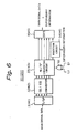
- Figure 6 is a view of one example of a coding circuit.
- the figure shows the coding circuit 111 of Fig. 5.
- the coding circuit 211 of Fig. 5 is of exactly the same construction.
- Reference numerals 41 to 45 show component elements of the coding circuit 211 side.
- Figure 7 is a view of one example of a decoding circuit.
- the figure shows the decoding circuit 221 of Fig. 5, but the decoding circuit 121 of Fig. 5 has exactly the same construction.
- Reference numerals 51 to 55 show component elements of the decoding circuit 121 side.
- the first and second light transmission level reducing means 15 and 25 shown in Fig. 4 and Fig. 5 are composed of first and second all "0" converting circuits 33 and 34 which convert all of the downstream and upstream main signal data bits to "0", respectively.
- the first and second received light signal level reduction detecting means 14 and 24 are composed of first and second all "0" detecting circuits 53 and 63 which detect that all of the upstream and downstream main signal data bits are "0".
- the coding circuit 111 shown in Fig. 6 is composed of an S/P converting circuit (S/5P) 31 which converts the electrical main signal serial data (140 Mb/s) from the bipolar/unipolar converting circuit (B/U) 112 to five bits of parallel data, a 5B/6B converter 32 which converts the five bits of parallel output signal of the S/P converting circuit 31 to six bits of parallel output signal, an all "0" converting circuit 33 which converts the six bits of parallel output signal all to "0" based on the signal D1, L1 from the means 13 in the optical reception circuit 123 or the means 14 in the decoding circuit 121, an insertion circuit 34 which uses only one bit in the six bits of the parallel output signal from the all "0" converting circuit 33 as the supervisory information bit and inserts supervisory information (which may include so-called order wire signals) collected by its own office (10) into the supervisory information, and a P/S converting circuit (6P/S) which converts the six bits of the parallel signal of the five bits of
- the decoding circuit 221 shown in Fig. 7 is composed of an S/P converting circuit (S/6P) 61 which converts the serial data of the main signal data + supervisory information from the optical reception circuit (OR) 223 into six bits of parallel data, an extraction circuit 62 which separates the supervisory information obtained from the supervisory information bit in the six bits of the parallel output signal of the S/P converting circuit 61, an all "0" detecting circuit 63 which detects an all "0" state from the total six bits of the parallel data signal of the five bits of the parallel output signal from the S/P converting circuit 61 and the one bit of the output signal from the extraction circuit 62 and issues an all "0" detecting signal (L2), a 5B/6B converter 64 which converts the six bits of parallel signal coming through the all "0" detecting circuit 63 into five bits of parallel signal, and a P/S converting circuit (5P/S) which converts the five bits of parallel output to a serial output signal and sends the main signal data (140 Mb/
- the electrical main signal data is converted from bipolar signals to unipolar signals in the converting circuit 112 of the optical transmission line equipment 10 and input to the S/P converting circuit 31, whereby in the S/P converting circuit 31 it is converted into five bits of parallel signals, the above-mentioned five bits are given one bit of a supervisory information bit by the 5B/6B converter 32 to convert it to six bits of parallel data, and that data is input to the all "0" converting circuit 33.
- the all "0" converting circuit 23 monitors the light stoppage detecting signal D1 from the means 13 in the optical reception circuit 123 or the all "0" detecting signal L1 from the means 14 in the decoding circuit 121 and when neither of these is generated, passes the six bits of output from the converter 32 as they are. When either is generated, the six bits of data are all converted to "0".
- the insertion circuit 34 inserts the supervisory information obtained in its own office (10) in the one bit of the service bit at certain periods (every 18 words in Fig. 3).
- the P/S converting circuit 35 receives the five bits worth of main signal data and one bit of supervisory information or receives the five bits worth of all "0" main signal data plus the one bit of supervisory information, converts the same to a series signal, and sends it to the optical transmission circuit 113.
- the all "0" detecting circuit 63 judges if all of the five bits of the main signal data are "0". When all "0", it issues an all "0" detecting signal L2, gives the same to the means 25 in the coding circuit 211 in the same equipment 20 as mentioned before, and sends the parallel data as is to the 5B/6B converter 64.
- the converter 64 cuts the supervisory information bit, sends just the five bits of the parallel main signal data to the P/S converting circuit 65, converts the serial main signal data to bipolar data by the unipolar/bipolar converting circuit 222, and sends it out.
- the data is supplied to a multiplexer/demultiplexer in the telephone office, for example.
- the coding circuit 211 of the equipment 20 receives the all "0" detecting signal at the means 25, so in exactly the same way as explained with reference to Fig. 6, all bits except the supervisory information bit are converted to "0" and sent to the optical transmission line 27, so the light irradiation power at the cut surface of the optical fiber becomes extremely small and it is possible to protect the eyes of the systems maintenance personnel.
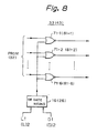
- Figure 8 is a view of one example of an all "0" converting circuit
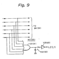
- Fig. 9 is a view of one example of an all "0" detecting circuit.
- the previously mentioned downstream transmission signal (Sd), that is, the main signal data, is processed by the parallel data converted from 5 bits to six bits in the first optical transmission line equipment 10.
- the first all "0" converting circuit 33 is composed of NOR gates 71-1 to 71-6 which have as first inputs the signals of each bit of the six bits and as common second inputs the output of the first OR gate means 16.
- the afore-mentioned upstream transmission signal Su is processed by the parallel data converted from five bits to six bits in the second optical transmission line equipment 20.
- the second all "0" converting circuit 43 is composed of NOR gates 81-1 to 81-6 which have as first inputs the signals of each of the bits of the six bits and have as common second inputs the output of the second OR gate means 26.
- the downstream transmission signal Sd that is, the main signal data
- the second all "0" detecting circuit is composed of a second OR gate 101 which has as its input each bit of the six bits.
- the upward transmission signal Su that is, the main signal data, is processed by the parallel data converted from five bit to six bits in the first optical transmission line equipment 10.
- the first all "0" detecting circuit 53 is composed of a first OR gate 91 which has as its input each bit of the six bits.
- a CR integrating circuit 102 912.
- An all "0" detecting output is obtained from the CR integrating circuit 102 (92) through a buffer 103 (93).
- the sixth bit of the input of the all "0" detecting circuit of Fig. 7 is the supervisory information bit. Once every subframe, the bit does not become “0", but becomes "1". At this time, all the bits do not become "0", so the data is passed through the integrating circuit 102 (92) and the bit "1" which appears at the sixth bit of the same is forcibly made “0".
- the decoding circuit fetches the supervisory information composed of the service bit and issues an all "0" detecting signal (L1, L2) of the main signal data bits after elimination of the supervisory information bit or else the optical reception circuit issues a light stoppage detecting signal (D1, D2) and the same is given to the coding circuit
- the coding circuit converts all the main signal data bits after removal of the supervisory bit "0", so it is possible to perform transmission of the supervisory data through the one normal optical transmission line. Further, only extremely low power laser light is sent out from the disconnected section of the optical transmission line, so there is no adverse effect on the eyes of the systems maintenance personnel.
Landscapes
- Physics & Mathematics (AREA)
- Electromagnetism (AREA)
- Engineering & Computer Science (AREA)
- Computer Networks & Wireless Communication (AREA)
- Signal Processing (AREA)
- Optics & Photonics (AREA)
- Optical Communication System (AREA)
- Dc Digital Transmission (AREA)
- Monitoring And Testing Of Transmission In General (AREA)
Applications Claiming Priority (2)
| Application Number | Priority Date | Filing Date | Title |
|---|---|---|---|
| JP1030681A JPH02209030A (ja) | 1989-02-09 | 1989-02-09 | 光伝送回線装置 |
| JP30681/89 | 1989-02-09 |
Publications (2)
| Publication Number | Publication Date |
|---|---|
| EP0382243A2 true EP0382243A2 (de) | 1990-08-16 |
| EP0382243A3 EP0382243A3 (de) | 1992-05-13 |
Family
ID=12310438
Family Applications (1)
| Application Number | Title | Priority Date | Filing Date |
|---|---|---|---|
| EP19900102582 Ceased EP0382243A3 (de) | 1989-02-09 | 1990-02-09 | Optisches Übertragungsleitungssystem |
Country Status (3)
| Country | Link |
|---|---|
| US (1) | US5099349A (de) |
| EP (1) | EP0382243A3 (de) |
| JP (1) | JPH02209030A (de) |
Cited By (10)
| Publication number | Priority date | Publication date | Assignee | Title |
|---|---|---|---|---|
| EP0437162A2 (de) * | 1990-01-09 | 1991-07-17 | International Business Machines Corporation | Sicherheitssteuersystem für Lichtwellenleiterverbindung |
| EP0553416A1 (de) * | 1992-01-30 | 1993-08-04 | KRONE Aktiengesellschaft | Verfahren und Anordnung zum Betrieb von optischen Verteilnetzen |
| GB2285192A (en) * | 1993-12-07 | 1995-06-28 | Northern Telecom Ltd | Network surveillance |
| GB2293708A (en) * | 1994-09-27 | 1996-04-03 | Fujitsu Ltd | Optical signal transmission apparatus and method |
| EP0903875A2 (de) * | 1997-09-18 | 1999-03-24 | Lucent Technologies Inc. | Automatisches Leistungsabschaltungssystem einer optischen Übertragungsstrecke |
| EP1006682A2 (de) * | 1998-12-04 | 2000-06-07 | Lucent Technologies Inc. | Automatisches Leistungsabschaltungssystem einer optischen Übertragungssystem |
| GB2348063A (en) * | 1999-03-19 | 2000-09-20 | Marconi Comm Ltd | Optical supervisory channel for monitoring faults in light-guides |
| GB2372655A (en) * | 2001-02-22 | 2002-08-28 | Fujitsu Ltd | Optical Amplifier, Optical Multiplexing Transmission System Using a Raman Light Source |
| GB2383213A (en) * | 2001-11-16 | 2003-06-18 | Agilent Technologies Inc | Open fiber control for optical transceivers |
| EP2288176A3 (de) * | 2000-05-30 | 2011-05-04 | Nortel Networks Limited | Mehrfachzugriffsystem für ein Kommunikationsnetzwerk |
Families Citing this family (13)
| Publication number | Priority date | Publication date | Assignee | Title |
|---|---|---|---|---|
| US5287211A (en) * | 1991-11-27 | 1994-02-15 | At&T Bell Laboratories | Multipath optical transmission system controller |
| US5353147A (en) * | 1991-11-27 | 1994-10-04 | At&T Bell Laboratories | Identification of transmission characteristic |
| US5428471A (en) * | 1992-07-30 | 1995-06-27 | Alcatel Network Systems, Inc. | Fail-safe automatic shut-down apparatus and method for high output power optical communications system |
| US5771114A (en) * | 1995-09-29 | 1998-06-23 | Rosemount Inc. | Optical interface with safety shutdown |
| US6288813B1 (en) * | 1998-03-25 | 2001-09-11 | The United States Of America As Represented By The Administrator Of The National Aeronautics And Space Administration | Apparatus and method for effecting data transfer between data systems |
| JP2001217778A (ja) * | 2000-02-03 | 2001-08-10 | Kanagawa Acad Of Sci & Technol | 光送受信機 |
| US7392281B1 (en) | 2000-02-25 | 2008-06-24 | Navic Systems, Inc. | System and method for providing guaranteed delivery of messages to embedded devices over a data network |
| JP4266491B2 (ja) * | 2000-04-28 | 2009-05-20 | キヤノン株式会社 | 光空間伝送装置 |
| US7047273B2 (en) | 2000-11-28 | 2006-05-16 | Navic Systems, Inc. | Load balancing in set top cable box environment |
| US7957643B2 (en) * | 2002-03-07 | 2011-06-07 | Alcatel-Lucent Usa Inc. | Method and apparatus for automatically controlling optical signal power in optical transmission systems |
| US6922531B2 (en) * | 2002-03-21 | 2005-07-26 | Nortel Networks Limited | Method and system for encoding optical communication information during automatic laser shutdown restart sequence |
| JP4584563B2 (ja) * | 2003-10-07 | 2010-11-24 | パイオニア株式会社 | 光伝送システム |
| US20060280055A1 (en) * | 2005-06-08 | 2006-12-14 | Miller Rodney D | Laser power control and device status monitoring for video/graphic applications |
Citations (4)
| Publication number | Priority date | Publication date | Assignee | Title |
|---|---|---|---|---|
| EP0077232A1 (de) * | 1981-10-02 | 1983-04-20 | Merlin Gerin | Fernübertragungssystem mit Lichtwellenleiter |
| DE3147555A1 (de) * | 1981-12-01 | 1983-06-09 | Siemens AG, 1000 Berlin und 8000 München | Schaltungsanordnung zur ueberwachung einer optischen uebertragungsstrecke |
| EP0136271A1 (de) * | 1983-09-01 | 1985-04-03 | Telefonaktiebolaget L M Ericsson | Vorrichtung zur Ermittlung der Entnahme von Lichtenergie von einer optischen Faser |
| GB2195508A (en) * | 1986-09-27 | 1988-04-07 | Stc Plc | Optical fibre transmission system |
Family Cites Families (2)
| Publication number | Priority date | Publication date | Assignee | Title |
|---|---|---|---|---|
| JPH01103332A (ja) * | 1987-10-16 | 1989-04-20 | Nec Corp | 光伝送装置 |
| US4994675A (en) * | 1989-04-28 | 1991-02-19 | Rebo Research, Inc. | Method and apparatus for checking continuity of optic transmission |
-
1989
- 1989-02-09 JP JP1030681A patent/JPH02209030A/ja active Pending
-
1990
- 1990-02-09 EP EP19900102582 patent/EP0382243A3/de not_active Ceased
- 1990-02-09 US US07/477,538 patent/US5099349A/en not_active Expired - Fee Related
Patent Citations (4)
| Publication number | Priority date | Publication date | Assignee | Title |
|---|---|---|---|---|
| EP0077232A1 (de) * | 1981-10-02 | 1983-04-20 | Merlin Gerin | Fernübertragungssystem mit Lichtwellenleiter |
| DE3147555A1 (de) * | 1981-12-01 | 1983-06-09 | Siemens AG, 1000 Berlin und 8000 München | Schaltungsanordnung zur ueberwachung einer optischen uebertragungsstrecke |
| EP0136271A1 (de) * | 1983-09-01 | 1985-04-03 | Telefonaktiebolaget L M Ericsson | Vorrichtung zur Ermittlung der Entnahme von Lichtenergie von einer optischen Faser |
| GB2195508A (en) * | 1986-09-27 | 1988-04-07 | Stc Plc | Optical fibre transmission system |
Non-Patent Citations (1)
| Title |
|---|
| PATENT ABSTRACTS OF JAPAN vol. 10, no. 75 (E-390)(2132) 5 November 1985 & JP-A-60 220 633 ( NIPPON DENKI ) * |
Cited By (24)
| Publication number | Priority date | Publication date | Assignee | Title |
|---|---|---|---|---|
| EP0437162A2 (de) * | 1990-01-09 | 1991-07-17 | International Business Machines Corporation | Sicherheitssteuersystem für Lichtwellenleiterverbindung |
| EP0437162A3 (en) * | 1990-01-09 | 1992-05-13 | International Business Machines Corporation | Optical fiber link control safety system |
| EP0553416A1 (de) * | 1992-01-30 | 1993-08-04 | KRONE Aktiengesellschaft | Verfahren und Anordnung zum Betrieb von optischen Verteilnetzen |
| GB2285192A (en) * | 1993-12-07 | 1995-06-28 | Northern Telecom Ltd | Network surveillance |
| US5615033A (en) * | 1994-09-27 | 1997-03-25 | Fujitsu Limited | Optical signal transmission apparatus and method |
| GB2293708B (en) * | 1994-09-27 | 1996-09-11 | Fujitsu Ltd | Optical signal transmission apparatus and method |
| GB2293708A (en) * | 1994-09-27 | 1996-04-03 | Fujitsu Ltd | Optical signal transmission apparatus and method |
| US6359708B1 (en) | 1997-09-18 | 2002-03-19 | Lucent Technologies Inc. | Optical transmission line automatic power reduction system |
| EP0903875A2 (de) * | 1997-09-18 | 1999-03-24 | Lucent Technologies Inc. | Automatisches Leistungsabschaltungssystem einer optischen Übertragungsstrecke |
| EP0903875A3 (de) * | 1997-09-18 | 2001-01-10 | Lucent Technologies Inc. | Automatisches Leistungsabschaltungssystem einer optischen Übertragungsstrecke |
| EP1006682A2 (de) * | 1998-12-04 | 2000-06-07 | Lucent Technologies Inc. | Automatisches Leistungsabschaltungssystem einer optischen Übertragungssystem |
| US6504630B1 (en) | 1998-12-04 | 2003-01-07 | Lucent Technologies Inc. | Automatic power shut-down arrangement for optical line systems |
| EP1006682A3 (de) * | 1998-12-04 | 2000-12-20 | Lucent Technologies Inc. | Automatisches Leistungsabschaltungssystem einer optischen Übertragungssystem |
| GB2348063B (en) * | 1999-03-19 | 2001-03-07 | Marconi Comm Ltd | Optical communication system |
| US6483616B1 (en) | 1999-03-19 | 2002-11-19 | Marconi Communications Limited | Safe repair of malfunction in optical communication system |
| GB2348063A (en) * | 1999-03-19 | 2000-09-20 | Marconi Comm Ltd | Optical supervisory channel for monitoring faults in light-guides |
| EP1041747A3 (de) * | 1999-03-19 | 2003-08-13 | Marconi Communications Limited | Optisches bidirektionelles Übertragungssystem mit Überwachunskanal |
| EP2271005A1 (de) * | 1999-03-19 | 2011-01-05 | Ericsson AB | Optisches bidirektionelles Übertragungssystem mit Überwachunskanal |
| EP2288176A3 (de) * | 2000-05-30 | 2011-05-04 | Nortel Networks Limited | Mehrfachzugriffsystem für ein Kommunikationsnetzwerk |
| GB2372655A (en) * | 2001-02-22 | 2002-08-28 | Fujitsu Ltd | Optical Amplifier, Optical Multiplexing Transmission System Using a Raman Light Source |
| US6532102B2 (en) | 2001-02-22 | 2003-03-11 | Fujitsu Limited | Optical amplifier |
| GB2372655B (en) * | 2001-02-22 | 2003-07-09 | Fujitsu Ltd | Optical amplifier |
| GB2383213A (en) * | 2001-11-16 | 2003-06-18 | Agilent Technologies Inc | Open fiber control for optical transceivers |
| GB2383213B (en) * | 2001-11-16 | 2005-01-12 | Agilent Technologies Inc | Open fiber control for optical transceivers |
Also Published As
| Publication number | Publication date |
|---|---|
| US5099349A (en) | 1992-03-24 |
| EP0382243A3 (de) | 1992-05-13 |
| JPH02209030A (ja) | 1990-08-20 |
Similar Documents
| Publication | Publication Date | Title |
|---|---|---|
| US5099349A (en) | Optical transmission line system | |
| EP0581138B1 (de) | Betriebssichere automatische Abschaltvorrichtung und Verfahren für ein optisches Übertragungssystem mit hoher Ausgangsleitung | |
| US6359708B1 (en) | Optical transmission line automatic power reduction system | |
| CA1245737A (en) | Loop transmission system having automatic loop configuration control means | |
| EP0579029A2 (de) | Verbindungssicherung in einem digitalen Fernweldesystem | |
| DE10243582A1 (de) | Offene-Faser-Steuerung für optische Sende/Empfangsgeräte | |
| US5793481A (en) | System, method and device for monitoring a fiber optic cable | |
| US20020159113A1 (en) | Alarm control system and method | |
| RU2371857C2 (ru) | Быстродействующий способ защиты оптической сети передачи данных | |
| US5130836A (en) | Optical transceiver | |
| US5046807A (en) | Fibre optic transmission system | |
| EP0700606A1 (de) | Anordnung zum überwachen einer lichtwellenleiter-übertragungsstrecke | |
| EP2525529A2 (de) | Transponder, Repeater, und Endgerätausrüstung | |
| DE3246241A1 (de) | Optischer sternbus mit aktivem koppler | |
| CN207691811U (zh) | 一种基于otdr的自动配置光传输系统 | |
| JP2994470B2 (ja) | 光伝送装置 | |
| US20020181053A1 (en) | Optical communication system including replaceable electro-optic and opto-electric converters | |
| JP3045288B2 (ja) | 光信号出力停止の方法とその回路 | |
| US6810210B1 (en) | Communication path impairment detection for duplex optic communication link | |
| JP2830096B2 (ja) | 双方向光通信方式 | |
| JP2718284B2 (ja) | 光海底ケーブルシステム修理方式 | |
| JP3102406B2 (ja) | 光インタフェース障害検出装置 | |
| KR0135213B1 (ko) | 소네트(sonet)신호 전송중 프레임 에러 감지 회로 | |
| JP2956391B2 (ja) | 光加入者伝送装置の加入者線インタフェース部 | |
| KR19990061550A (ko) | 데이터 통신의 케이블 상태 검사장치 |
Legal Events
| Date | Code | Title | Description |
|---|---|---|---|
| PUAI | Public reference made under article 153(3) epc to a published international application that has entered the european phase |
Free format text: ORIGINAL CODE: 0009012 |
|
| AK | Designated contracting states |
Kind code of ref document: A2 Designated state(s): DE FR GB IT |
|
| PUAL | Search report despatched |
Free format text: ORIGINAL CODE: 0009013 |
|
| AK | Designated contracting states |
Kind code of ref document: A3 Designated state(s): DE FR GB IT |
|
| 17P | Request for examination filed |
Effective date: 19921111 |
|
| 17Q | First examination report despatched |
Effective date: 19950515 |
|
| GRAG | Despatch of communication of intention to grant |
Free format text: ORIGINAL CODE: EPIDOS AGRA |
|
| STAA | Information on the status of an ep patent application or granted ep patent |
Free format text: STATUS: THE APPLICATION HAS BEEN REFUSED |
|
| 18R | Application refused |
Effective date: 19960906 |