EP0381682B1 - Drehkolbenverdichter - Google Patents
Drehkolbenverdichter Download PDFInfo
- Publication number
- EP0381682B1 EP0381682B1 EP88908150A EP88908150A EP0381682B1 EP 0381682 B1 EP0381682 B1 EP 0381682B1 EP 88908150 A EP88908150 A EP 88908150A EP 88908150 A EP88908150 A EP 88908150A EP 0381682 B1 EP0381682 B1 EP 0381682B1
- Authority
- EP
- European Patent Office
- Prior art keywords
- rotor
- inner rotor
- rotary piston
- piston compressor
- shaft
- Prior art date
- Legal status (The legal status is an assumption and is not a legal conclusion. Google has not performed a legal analysis and makes no representation as to the accuracy of the status listed.)
- Expired - Lifetime
Links
- 229910001385 heavy metal Inorganic materials 0.000 claims abstract description 9
- 229910052751 metal Inorganic materials 0.000 claims abstract description 5
- 239000002184 metal Substances 0.000 claims abstract description 5
- 239000000463 material Substances 0.000 claims description 7
- 230000005540 biological transmission Effects 0.000 claims description 2
- 230000002035 prolonged effect Effects 0.000 claims 1
- 230000006835 compression Effects 0.000 abstract description 2
- 238000007906 compression Methods 0.000 abstract description 2
- 238000007789 sealing Methods 0.000 description 9
- 230000002093 peripheral effect Effects 0.000 description 6
- 238000004519 manufacturing process Methods 0.000 description 4
- 239000000314 lubricant Substances 0.000 description 3
- 238000012986 modification Methods 0.000 description 3
- 230000004048 modification Effects 0.000 description 3
- 229910000831 Steel Inorganic materials 0.000 description 2
- 239000011230 binding agent Substances 0.000 description 2
- UGKDIUIOSMUOAW-UHFFFAOYSA-N iron nickel Chemical compound [Fe].[Ni] UGKDIUIOSMUOAW-UHFFFAOYSA-N 0.000 description 2
- 230000000149 penetrating effect Effects 0.000 description 2
- 239000010959 steel Substances 0.000 description 2
- WFKWXMTUELFFGS-UHFFFAOYSA-N tungsten Chemical compound [W] WFKWXMTUELFFGS-UHFFFAOYSA-N 0.000 description 2
- 229910052721 tungsten Inorganic materials 0.000 description 2
- 239000010937 tungsten Substances 0.000 description 2
- 238000013459 approach Methods 0.000 description 1
- 238000005452 bending Methods 0.000 description 1
- 238000010276 construction Methods 0.000 description 1
- 238000005461 lubrication Methods 0.000 description 1
- 238000012423 maintenance Methods 0.000 description 1
Images
Classifications
-
- F—MECHANICAL ENGINEERING; LIGHTING; HEATING; WEAPONS; BLASTING
- F01—MACHINES OR ENGINES IN GENERAL; ENGINE PLANTS IN GENERAL; STEAM ENGINES
- F01B—MACHINES OR ENGINES, IN GENERAL OR OF POSITIVE-DISPLACEMENT TYPE, e.g. STEAM ENGINES
- F01B15/00—Reciprocating-piston machines or engines with movable cylinders other than provided for in group F01B13/00
-
- F—MECHANICAL ENGINEERING; LIGHTING; HEATING; WEAPONS; BLASTING
- F04—POSITIVE - DISPLACEMENT MACHINES FOR LIQUIDS; PUMPS FOR LIQUIDS OR ELASTIC FLUIDS
- F04C—ROTARY-PISTON, OR OSCILLATING-PISTON, POSITIVE-DISPLACEMENT MACHINES FOR LIQUIDS; ROTARY-PISTON, OR OSCILLATING-PISTON, POSITIVE-DISPLACEMENT PUMPS
- F04C18/00—Rotary-piston pumps specially adapted for elastic fluids
- F04C18/08—Rotary-piston pumps specially adapted for elastic fluids of intermeshing-engagement type, i.e. with engagement of co-operating members similar to that of toothed gearing
- F04C18/10—Rotary-piston pumps specially adapted for elastic fluids of intermeshing-engagement type, i.e. with engagement of co-operating members similar to that of toothed gearing of internal-axis type with the outer member having more teeth or tooth equivalents, e.g. rollers, than the inner member
-
- F—MECHANICAL ENGINEERING; LIGHTING; HEATING; WEAPONS; BLASTING
- F04—POSITIVE - DISPLACEMENT MACHINES FOR LIQUIDS; PUMPS FOR LIQUIDS OR ELASTIC FLUIDS
- F04C—ROTARY-PISTON, OR OSCILLATING-PISTON, POSITIVE-DISPLACEMENT MACHINES FOR LIQUIDS; ROTARY-PISTON, OR OSCILLATING-PISTON, POSITIVE-DISPLACEMENT PUMPS
- F04C29/00—Component parts, details or accessories of pumps or pumping installations, not provided for in groups F04C18/00 - F04C28/00
- F04C29/0021—Systems for the equilibration of forces acting on the pump
Definitions
- the invention relates to a rotary compressor according to the preamble of claim 1.
- the invention has for its object to provide a rotary compressor according to the preamble of claim 1, which is characterized by a large delivery rate at low drive speeds and allows high speeds of the external rotor.
- this compressor is particularly suitable for dry running. Dry-running compressors are used when lubricant-free compressed air is required. So no lubricant must get into the working chambers, which has the prerequisite that no sealing elements are provided are that need to be lubricated. Accordingly, such compressors with a gap seal in the order of 50 to 100 microns must be manufactured. Maintaining such narrow sealing gaps is made easier in the rotary piston compressor according to the invention by keeping drive tensile forces away from the internal rotor bet. However, the internal rotor is exposed to high centrifugal forces during operation, since it rotates at twice the drive speed in the 2: 1 machine.
- the inner rotor can be hollow and made of light metal and can accommodate at least one balancing weight made of a material with a higher specific weight that extends essentially over its entire length.
- the mass balance can be achieved by one or more heavy metal pins, for example made of tungsten in a nickel-iron binder, which extend through the inner rotor parallel to the axis of rotation and one of which can simultaneously be used to fix the inner rotor in rotation on its shaft.
- the shaft with the counterweight can be made in one piece and inserted with a press fit into a corresponding recess in the inner rotor.
- phase position between the inner and outer rotor is set extremely precisely. This phase position is maintained by the gear between the inner and outer rotor. While the external gear can be screwed directly onto the internal fan in non-dry-running compressors, this is not possible due to the need to lubricate the gearbox in dry-running compressors.
- the groove which receives the heavy metal pin used for rotation, beyond the inner rotor and the external gear outside the interior of the outer rotor on the Arrange the shaft and connect it to the shaft by means of a pin or projection which engages in the groove in the shaft.
- a single pin can also be provided on the shaft to prevent rotation of the inner rotor and the outer gear.
- radially inward projections can be formed on the inside of the outer peripheral wall of the inner rotor in the area diametrically opposite the hub, from which material can be removed for the purpose of balancing the rotor. If the end faces of the inner rotor are closed off by covers in order to prevent flow around the sides and to keep the leakage small, these projections are arranged near the end faces and the covers are provided in the area of the projections with openings through which a tool for removing material from the projections can be passed.
- the housing component in which the transmission-side end of the shaft is mounted can have a disk-shaped extension which extends between the inner rotor and the outer gear, has a bore for the shaft to pass through and, with its outer circumference, seals into a corresponding circular recess in the adjacent end wall of the outer rotor is used.
- both housing components in which the ends of the shaft are mounted and which extend through the end walls of the outer rotor, are provided with disk-shaped approaches, which are inserted into corresponding circular recesses in the end walls of the outer rotor, and plates are attached to the inner end walls of the outer rotor such that their inner surfaces are flush with the inner surfaces of the disc-shaped projections.
- a compensating disk of suitable thickness can be provided between one of the housing components and a shaft extension.
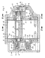
- the parallel-axis and internal-axis rotary piston compressor shown has a housing which is composed of a peripheral wall 1 and side parts 2 and 3 attached to it laterally, the left side part comprising a bearing plate 4 with a hub 5, an intermediate plate 6 and a hub 5 penetrating Bearing extension 7, while the right side part 3 consists only of a bearing plate 8 with a hub 9 and a bearing extension 10 penetrating this.
- An outer rotor 12 is mounted in the housing on the bearing hubs 5 and 8 via maintenance-free and encapsulated ball bearings 11, which has a cylindrical outer surface 13 and rotates with a small sealing gap in the corresponding cylindrical inner space 14 of the housing, as can be seen from FIG. 2.
- the interior 14 communicates with an inlet duct 15 and an outlet duct 16.
- a compressor chamber 17 in the form of an arena is provided in the outer rotor 12 and communicates with control openings 18 and 19 in the peripheral surface of the outer rotor.
- an inner rotor 20 with a circular cross section is arranged eccentrically on a shaft 21.
- the diameter of the inner rotor 20 corresponds to the diameter of the semicircular end sections of the compressor space 17 except for narrow sealing gaps of the order of 50 to 100 ⁇ m.
- the inner rotor shaft 21 is via bearings 22 in the bearing extensions 7 and 10 stored.
- the axis of rotation D 1 of the inner rotor shaft 21 runs parallel to the axis of rotation D 2 of the outer rotor 12.
- the inner and outer rotors are at a certain speed ratio to one another, which in the exemplary embodiment is 2: 1 and by a gear, consisting of an outer gear 23 arranged on the inner rotor shaft 21 and an internal gear 24 fastened to the external rotor 12.
- the outer rotor 12 is composed of a central part 25 and side walls 26 and 27, which are provided with circular openings 28 and 29, into which the bearing extensions 7 and 10 protrude.
- a drive pulley 30 is connected to the left side wall 27 of the external rotor 12 in FIG. 1.
- the bearing extension 10 is provided with a disk-shaped extension 31, which is sealingly inserted into the opening 28 in the outer rotor side wall 26 via a sealing ring 32 is.
- the outer rotor side wall 27 is sealingly inserted into a corresponding circular opening 34 in the intermediate housing part 6 via seals 33.
- the inner rotor 20 is made as light as possible.
- it is hollow and made of light metal and consists of an outer circumferential wall 40 and a hub 41 which is interspersed with the bet 21.
- Heavy-duty pins 42 and 43 are provided, which extend over the entire length of the inner rotor 20.
- the heavy metal pins are made of a material with a high specific weight, for example tungsten in a nickel-iron binder.
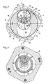
- a full mass balance of the inner rotor 20 is achieved in each plane running perpendicular to its longitudinal central axis M.
- the heavy-duty pin 43 is also used for the rotationally fixed connection of the inner rotor 20 to the shaft 21, and a groove 44 and 45, which is semicircular in cross-section, is provided in the hub 41 and in the shaft 21 for receiving it.
- the groove 44 extends in Fig. 1 to the right beyond the inner rotor 20 and at the same time serves for the rotationally fixed and positionally correct arrangement of the external gear 23, which engages with a corresponding nose 47 (FIG. 3) in the groove 44.
- the pin 43 in FIG. 1 could be extended to the right and establish the rotationally fixed connection between the shaft 21 and the external gear 23.
- a balancing option is provided.
- radially inwardly directed projections 46 are provided on the inside of the outer peripheral wall 40 of the inner rotor 20 in the area diametrically opposite the hub 41.
- the inner rotor 20 can be completely balanced by removing material from the projections 40.
- openings are provided in these covers, through which the projections 46 can be machined.
- Narrow sealing gaps usually result in tight tolerances, which require a high manufacturing effort.
- 12 plates 50 are provided on the inner surfaces of the side walls 26, 27 of the outer rotor, the thickness of which is selected so that its inner surfaces are aligned with the inner surfaces of the disk-shaped projections 31 and 31a after assembly.
- the inside diameter of the plate 50 on the right in FIG. 1 is smaller than the diameter of the opening 28, so that lubricant passing over the seal 32 cannot get into the compressor chamber 17.
- the axial position of the inner rotor 20 relative to the outer rotor 12 is achieved by a shim 51 between the bearing 22 for the shaft 21 and the outer gear 23.
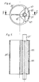
- an inner rotor 20 ' is shown, the shaft 21' is in one piece with a balance weight 65 and consists, for example, of a precision-drawn steel part. This steel part is inserted with a press fit in an opening 66 of the inner rotor 20 'and is at the points 67 of the opening with a fit.
- the balance weight 65 extends, as shown in Fig. 5, over the entire length of the inner rotor 20 ', so that there is a full mass balance in each transverse plane of the inner rotor as in the inner rotor 20 of Fig. 1.
Landscapes
- Engineering & Computer Science (AREA)
- Mechanical Engineering (AREA)
- General Engineering & Computer Science (AREA)
- Applications Or Details Of Rotary Compressors (AREA)
- Compressors, Vaccum Pumps And Other Relevant Systems (AREA)
- Rotary Pumps (AREA)
Applications Claiming Priority (4)
| Application Number | Priority Date | Filing Date | Title |
|---|---|---|---|
| DE3733398 | 1987-10-02 | ||
| DE3733398 | 1987-10-02 | ||
| DE3744637 | 1987-12-31 | ||
| DE19873744637 DE3744637A1 (de) | 1987-10-02 | 1987-12-31 | Drehkolbenverdichter |
Publications (2)
| Publication Number | Publication Date |
|---|---|
| EP0381682A1 EP0381682A1 (de) | 1990-08-16 |
| EP0381682B1 true EP0381682B1 (de) | 1991-12-04 |
Family
ID=25860442
Family Applications (1)
| Application Number | Title | Priority Date | Filing Date |
|---|---|---|---|
| EP88908150A Expired - Lifetime EP0381682B1 (de) | 1987-10-02 | 1988-09-30 | Drehkolbenverdichter |
Country Status (5)
| Country | Link |
|---|---|
| US (1) | US5076768A (enExample) |
| EP (1) | EP0381682B1 (enExample) |
| JP (1) | JPH02502035A (enExample) |
| DE (2) | DE3744637A1 (enExample) |
| WO (1) | WO1989002985A1 (enExample) |
Families Citing this family (5)
| Publication number | Priority date | Publication date | Assignee | Title |
|---|---|---|---|---|
| KR920700352A (ko) * | 1989-03-31 | 1992-02-19 | 원본미기재 | 회전식 피스톤 압축기 |
| JP2000027772A (ja) * | 1998-07-08 | 2000-01-25 | Matsushita Electric Ind Co Ltd | 密閉型圧縮機 |
| ITTV20030089A1 (it) * | 2003-06-19 | 2003-09-17 | Orlando Canal | Meccanismo per gas-dinamica azione volumetrica alterno rotativa a 60 grado, "gavara-60", per uso generale e particolarmente per motori endotermic |
| US9267504B2 (en) | 2010-08-30 | 2016-02-23 | Hicor Technologies, Inc. | Compressor with liquid injection cooling |
| US8794941B2 (en) | 2010-08-30 | 2014-08-05 | Oscomp Systems Inc. | Compressor with liquid injection cooling |
Citations (1)
| Publication number | Priority date | Publication date | Assignee | Title |
|---|---|---|---|---|
| US883271A (en) * | 1907-09-16 | 1908-03-31 | George Wilson | Rotary pump. |
Family Cites Families (13)
| Publication number | Priority date | Publication date | Assignee | Title |
|---|---|---|---|---|
| US1753476A (en) * | 1927-06-29 | 1930-04-08 | Joseph R Richer | Rotary pump or blower |
| US1887884A (en) * | 1929-07-18 | 1932-11-15 | Powerplus 1927 Ltd | Rotary pump machine |
| US1897190A (en) * | 1930-04-22 | 1933-02-14 | Powerplus 1927 Ltd | Rotary pump machine |
| DE1000029B (de) * | 1955-03-30 | 1957-01-03 | Gerhard Von Der Heyde | Drehkolbenmaschine |
| US3012550A (en) * | 1958-10-07 | 1961-12-12 | Nsu Motorenwerke Ag | Rotary mechanism bearing arrangement |
| US3311094A (en) * | 1964-08-18 | 1967-03-28 | Kehl Henry | Rotary engine |
| BE794675A (fr) * | 1972-02-08 | 1973-05-16 | Renault | Distribution de machine rotative |
| DE2544795A1 (de) * | 1975-10-07 | 1977-04-21 | Gerhard Von Der Heyde | Drehkolbenmaschine |
| DE2604665A1 (de) * | 1976-02-06 | 1977-08-11 | Sullair Europ Corp | Drehkolbenmaschine |
| CH664193A5 (de) * | 1982-03-03 | 1988-02-15 | Wankel Felix | Abgasbetriebener rotationskolbenlader. |
| KR840007619A (ko) * | 1983-02-04 | 1984-12-08 | 미다가쓰시게 | 압축기의 용량제어방법 및 그 장치 |
| DE3445653A1 (de) * | 1984-12-14 | 1986-06-19 | Wankel Gmbh, 1000 Berlin | Auswuchtung eines parallel- und aussenachsigen im kaemmeingriff arbeitenden rotationskolbengeblaeses |
| US4915596A (en) * | 1988-10-24 | 1990-04-10 | Mccall William B | Pure rotary positive displacement device |
-
1987
- 1987-12-31 DE DE19873744637 patent/DE3744637A1/de not_active Withdrawn
-
1988
- 1988-09-30 WO PCT/DE1988/000601 patent/WO1989002985A1/de not_active Ceased
- 1988-09-30 JP JP63507552A patent/JPH02502035A/ja active Granted
- 1988-09-30 US US07/466,306 patent/US5076768A/en not_active Expired - Fee Related
- 1988-09-30 EP EP88908150A patent/EP0381682B1/de not_active Expired - Lifetime
- 1988-09-30 DE DE8888908150T patent/DE3866706D1/de not_active Expired - Lifetime
Patent Citations (1)
| Publication number | Priority date | Publication date | Assignee | Title |
|---|---|---|---|---|
| US883271A (en) * | 1907-09-16 | 1908-03-31 | George Wilson | Rotary pump. |
Also Published As
| Publication number | Publication date |
|---|---|
| JPH0357308B2 (enExample) | 1991-08-30 |
| DE3744637A1 (de) | 1989-04-13 |
| EP0381682A1 (de) | 1990-08-16 |
| WO1989002985A1 (fr) | 1989-04-06 |
| US5076768A (en) | 1991-12-31 |
| DE3866706D1 (de) | 1992-01-16 |
| JPH02502035A (ja) | 1990-07-05 |
Similar Documents
| Publication | Publication Date | Title |
|---|---|---|
| DE3126243C2 (de) | Nebenantrieb einer Brennkraftmaschine | |
| DE3619754C2 (enExample) | ||
| DE1553275C3 (de) | Rotationskolbenmaschine für Flüssigkeiten | |
| DE2700522C2 (enExample) | ||
| EP0807030A1 (de) | Antriebsvorrichtung, insbesondere radantrieb für kettenfahrzeuge | |
| DE19513380C2 (de) | Abdichtung, Lagerung und Antrieb der Rotoren eines trockenlaufenden Schraubenrotorverdichters | |
| DE3921221C2 (de) | Gekapselter Rotationskolbenkompressor | |
| DE3720745C2 (enExample) | ||
| DE2246901A1 (de) | Von fluid durchstroemte fluegelzellenmaschine | |
| EP0666422B1 (de) | Lagerung und Antrieb der Rotoren eines Schraubenrotorverdichters | |
| EP0394651A1 (de) | Druckluftlamellenmotor | |
| EP0080670A1 (de) | Drehvorrichtung für hängende Lasten | |
| DE69122195T2 (de) | Spiralverdichter | |
| DE2710734C3 (enExample) | ||
| EP0381682B1 (de) | Drehkolbenverdichter | |
| DE3342131C2 (enExample) | ||
| DE3716083A1 (de) | Innenachsige drehkolbenmaschine | |
| DE3828090C2 (enExample) | ||
| DE4421255C1 (de) | Füllstücklose Innenzahnradpumpe | |
| DE2902301C2 (de) | Flügelzellenpumpe | |
| EP0475109B1 (de) | Innenzahnradpumpe für Hydraulikflüssigkeit | |
| EP0474001B1 (de) | Innenzahnradpumpe für Hydraulikflüssigkeit | |
| EP0473025B1 (de) | Innenzahnradpumpe für Hydraulikflüssigkeit | |
| WO1990012210A1 (de) | Drehkolbenverdichter | |
| DE3346519C2 (enExample) |
Legal Events
| Date | Code | Title | Description |
|---|---|---|---|
| PUAI | Public reference made under article 153(3) epc to a published international application that has entered the european phase |
Free format text: ORIGINAL CODE: 0009012 |
|
| AK | Designated contracting states |
Kind code of ref document: A1 Designated state(s): DE FR GB IT SE |
|
| 17P | Request for examination filed |
Effective date: 19900322 |
|
| 17Q | First examination report despatched |
Effective date: 19910422 |
|
| GRAA | (expected) grant |
Free format text: ORIGINAL CODE: 0009210 |
|
| AK | Designated contracting states |
Kind code of ref document: B1 Designated state(s): DE FR GB IT SE |
|
| PG25 | Lapsed in a contracting state [announced via postgrant information from national office to epo] |
Ref country code: IT Free format text: LAPSE BECAUSE OF FAILURE TO SUBMIT A TRANSLATION OF THE DESCRIPTION OR TO PAY THE FEE WITHIN THE PRE;WARNING: LAPSES OF ITALIAN PATENTS WITH EFFECTIVE DATE BEFORE 2007 MAY HAVE OCCURRED AT ANY TIME BEFORE 2007. THE CORRECT EFFECTIVE DATE MAY BE DIFFERENT FROM THE ONE RECORDED.SCRIBED TIME-LIMIT Effective date: 19911204 Ref country code: FR Effective date: 19911204 Ref country code: SE Effective date: 19911204 |
|
| REF | Corresponds to: |
Ref document number: 3866706 Country of ref document: DE Date of ref document: 19920116 |
|
| GBT | Gb: translation of ep patent filed (gb section 77(6)(a)/1977) | ||
| EN | Fr: translation not filed | ||
| PG25 | Lapsed in a contracting state [announced via postgrant information from national office to epo] |
Ref country code: GB Effective date: 19920930 |
|
| PLBE | No opposition filed within time limit |
Free format text: ORIGINAL CODE: 0009261 |
|
| STAA | Information on the status of an ep patent application or granted ep patent |
Free format text: STATUS: NO OPPOSITION FILED WITHIN TIME LIMIT |
|
| 26N | No opposition filed | ||
| GBPC | Gb: european patent ceased through non-payment of renewal fee |
Effective date: 19920930 |
|
| PGFP | Annual fee paid to national office [announced via postgrant information from national office to epo] |
Ref country code: DE Payment date: 20000222 Year of fee payment: 12 |
|
| PG25 | Lapsed in a contracting state [announced via postgrant information from national office to epo] |
Ref country code: DE Free format text: LAPSE BECAUSE OF NON-PAYMENT OF DUE FEES Effective date: 20010601 |