EP0380780A1 - Freewheel - Google Patents
Freewheel Download PDFInfo
- Publication number
- EP0380780A1 EP0380780A1 EP89122291A EP89122291A EP0380780A1 EP 0380780 A1 EP0380780 A1 EP 0380780A1 EP 89122291 A EP89122291 A EP 89122291A EP 89122291 A EP89122291 A EP 89122291A EP 0380780 A1 EP0380780 A1 EP 0380780A1
- Authority
- EP
- European Patent Office
- Prior art keywords
- cage
- clamping ring
- axially
- hand
- intermediate member
- Prior art date
- Legal status (The legal status is an assumption and is not a legal conclusion. Google has not performed a legal analysis and makes no representation as to the accuracy of the status listed.)
- Granted
Links
- 230000006835 compression Effects 0.000 claims description 12
- 238000007906 compression Methods 0.000 claims description 12
- 238000009434 installation Methods 0.000 abstract 1
- 238000006073 displacement reaction Methods 0.000 description 2
- 238000010276 construction Methods 0.000 description 1
Images

Classifications
-
- F—MECHANICAL ENGINEERING; LIGHTING; HEATING; WEAPONS; BLASTING
- F16—ENGINEERING ELEMENTS AND UNITS; GENERAL MEASURES FOR PRODUCING AND MAINTAINING EFFECTIVE FUNCTIONING OF MACHINES OR INSTALLATIONS; THERMAL INSULATION IN GENERAL
- F16D—COUPLINGS FOR TRANSMITTING ROTATION; CLUTCHES; BRAKES
- F16D41/00—Freewheels or freewheel clutches
- F16D41/06—Freewheels or freewheel clutches with intermediate wedging coupling members between an inner and an outer surface
- F16D41/08—Freewheels or freewheel clutches with intermediate wedging coupling members between an inner and an outer surface with provision for altering the freewheeling action
- F16D41/086—Freewheels or freewheel clutches with intermediate wedging coupling members between an inner and an outer surface with provision for altering the freewheeling action the intermediate members being of circular cross-section and wedging by rolling
- F16D41/088—Freewheels or freewheel clutches with intermediate wedging coupling members between an inner and an outer surface with provision for altering the freewheeling action the intermediate members being of circular cross-section and wedging by rolling the intermediate members being of only one size and wedging by a movement not having an axial component, between inner and outer races, one of which is cylindrical
Definitions
- the invention relates to a freewheel comprising a clamping ring which has clamping ramps and spring-loaded clamping rollers which are accommodated in pockets of a cage and which are assigned to the clamping ramps and which can be switched from a first to a second switching position by rotating the cage relative to the clamping ring.
- a freewheel of this type is known for example from DE-PS 30 02 402.
- the cage is pressed into a switching position by a spring designed as a simple wire ring.
- a switching element is formed on the wire ring, on which a tangentially directed force acts and can thereby turn the cage into a second switching position. Since the force required to rotate the cage must act tangentially, this freewheel can only be used where the freewheel sleeve does not rotate with the cage.
- the freewheel cage is moved from one switching position to another.
- the bolt When it is pressed again, through which the first switching position is to be reached again, the bolt lifts off the inclined surface of the cage and this has to be turned back into its original position by an additional spring.
- the design of this known freewheel is rather complicated in that the bolt required for switching, as well as its operating linkage, are additional components which have to be accommodated outside the actual freewheel.
- the cage is returned to its starting position exclusively by the force of a spring, so that, for example in the event of a broken spring, it is no longer possible to switch over the freewheel.
- the invention has for its object to design a freewheel of this type with simple constructive means so that it can be supplied as a ready-to-install unit that can be manufactured very inexpensively with perfect functionality and only an external, simple switching element, for example, for its operation must be provided in the form of a longitudinally displaceable ring.
- the cage interlocks directly or with the engagement of an intermediate member and the clamping ring with projections and recesses such that the cage performs a rotational movement with respect to the clamping ring when the cage or the intermediate member is axially displaced.
- the cage can be axially displaceably mounted in the clamping ring, which has radially directed ribs at both ends, an axially acting compression spring being arranged between the one clamping ring rim and a cage end face, while on the opposite side an axial extension of the cage, the axial extends beyond the clamping ring, has recesses or projections which cooperate with projections or recesses on the clamping ring in a thread-like manner.
- such a construction could be carried out so that the approach of the cage with at least one threaded projection, for. B. is provided in the form of a radially projecting bar which engages in a form-fitting manner in a recess of the clamping ring rim opposite the compression spring.
- no additional parts are required in this embodiment apart from the compression spring used compared to a non-switchable freewheel. Only existing parts, namely the cage on the one hand and the clamping ring on the other hand, have to be given a special design by means of which the cage is rotated relative to the clamping ring.
- the cage is axially displaced during switching
- another embodiment is also possible according to the invention in which the cage does not have to be axially displaced.
- the cage is axially immovable in the clamping ring between radially directed ribs at both ends, between the cage and clamping ring a preferably cylindrical, axially displaceably mounted and axially pressed out under the action of a compression spring, which is arranged axially via protrudes the clamping ring, the cage and the intermediate member on the one hand and the intermediate member and the clamping ring on the other hand, on the one hand, thread-like and, on the other hand, intermesh in the sense of a longitudinal guide, that when the Intermediate member of the cage performs a rotational movement with respect to the clamping ring.
- an axial extension of the cage can be provided with at least one threaded projection which engages in a corresponding groove of the intermediate member, which on the other hand is provided with at least one axially extending groove in which a projection of a clamping ring rim engages in a form-fitting manner.
- the freewheel shown in Figures 1 and 2 consists of the clamping ring 1, which has clamping ramps 2 in its bore and it has a cage 3, in the pockets 4 clamping rollers 5 are housed, which are under the action of springs 6.
- the clamping ring 1 has on both axial ends radially inwardly directed rims 7 and 8. Between the rim 7 on the one hand and the cage end face 9 on the other hand, a compression spring 10 is arranged, which in the example shown consists of two wave springs which are separated from one another by an intermediate washer.
- the cage 3 is provided at one end with an axial projection 11 which has thread-shaped projections at some circumferential points 12 which are inclined at an angle ⁇ to the longitudinal axis and which engage in corresponding recesses 13 of the rim 8.
- an axial projection 11 which has thread-shaped projections at some circumferential points 12 which are inclined at an angle ⁇ to the longitudinal axis and which engage in corresponding recesses 13 of the rim 8.
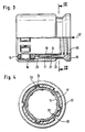
- FIG. 3 and 4 differs from the previous one in that the cage 15 is not axially displaced when actuated.
- an intermediate member 17 is provided in this case between the cage 15 on the one hand and the clamping ring 16 on the other hand, which is designed as a cylindrical sleeve which projects axially at one end over the clamping ring 16 and has a thrust collar 18 there .
- An axially acting compression spring 20 is connected between the axial extension 19 of the cage 15 on the one hand and a shoulder in the run-up collar 18.
- a nose 21 is provided on the intermediate member 17, which is supported on the clamping ring rim 22.
- the axial extension 19 carries, at some circumferential locations, threaded projections 23 which engage in corresponding grooves 24 in the intermediate member 17.
- the intermediate member 17 is provided at several circumferential locations with axially extending grooves 25, into which projections 26 of the clamping ring rim 22 engage.
- the invention can also be used in such known freewheels in which the clamping ramps are designed such that, starting from a cage position in which the freewheel clamps in one direction of rotation, a central position is reached by rotating the cage, in which the freewheel in none of the jams in both directions of rotation and by further turning the cage a switching position is finally reached in which it jams in the opposite direction to the first switching position.
Abstract
Description
Die Erfindung betrifft einen Freilauf, bestehend aus einem Klemmring, der Klemmrampen aufweist, und aus in Taschen eines Käfigs untergebrachten federbelasteten Klemmrollen, die den Klemmrampen zugeordnet sind, der durch Verdrehen des Käfigs gegenüber dem Klemmring aus einer ersten in eine zweite Schaltstellung umschaltbar ist.The invention relates to a freewheel comprising a clamping ring which has clamping ramps and spring-loaded clamping rollers which are accommodated in pockets of a cage and which are assigned to the clamping ramps and which can be switched from a first to a second switching position by rotating the cage relative to the clamping ring.
Ein Freilauf dieser Gattung ist beispielsweise aus der DE-PS 30 02 402 bekannt. Bei diesem Freilauf wird der Käfig durch eine als einfacher Drahtring ausgebildete Feder in eine Schaltstellung gedrückt. An dem Drahtring ist ein Schaltglied ausgebildet, auf welches eine tangential gerichtete Kraft einwirken und dadurch den Käfig in eine zweite Schaltstellung verdrehen kann. Da die für die Verdrehung des Käfigs benötigte Kraft tangential angreifen muß, kann dieser Freilauf nur dort eingesetzt werden, wo die Freilaufhülse mit dem Käfig nicht rotiert.A freewheel of this type is known for example from DE-PS 30 02 402. In this freewheel, the cage is pressed into a switching position by a spring designed as a simple wire ring. A switching element is formed on the wire ring, on which a tangentially directed force acts and can thereby turn the cage into a second switching position. Since the force required to rotate the cage must act tangentially, this freewheel can only be used where the freewheel sleeve does not rotate with the cage.
Dieses Problem ist bei einem weiteren bekannten Freilauf (GB-A 21 50 239) dadurch gelöst, daß die für die Umschaltung benötigte Kraft in axialer Richtung wirkt. Dadurch ist es möglich, eine Umschaltung des Freilaufs auch dann zu bewirken, wenn der Käfig rotiert. Bei diesem bekannten Freilauf ist der die Klemmrollen aufnehmende Käfig mit einer axialen Verlängerung versehen, die an zwei einander diametral gegenüberliegenden Stellen Durchbrüche von im wesentlichen dreieckiger Form aufweist. Die eine Seitenkante des Dreiecks verläuft dabei geneigt zur Freilauflängsachse. In diese Durchbrüche greift ein zum Käfig drehfest, jedoch axial verschieblich gelagerter Bolzen ein, der durch ein Schaltgestänge in axialer Richtung verschoben werden kann. Er legt sich dabei an die zur Freilauflängsachse geneigten Kanten der Durchbrüche am Käfig an und verdreht diesen dadurch bei seiner Längsverschiebung. Der Freilaufkäfig wird dabei von der einen Schaltstellung in eine andere gebracht. Beim erneuten Betätigen, durch welches die erste Schaltstellung wieder erreicht werden soll, hebt der Bolzen von der Schrägfläche des Käfigs ab und dieser muß durch eine zusätzliche Feder in seine ursprüngliche Lage zurückgedreht werden. Dieser bekannte Freilauf ist in seinem konstruktiven Aufbau dadurch recht kompliziert, daß der zum Schalten erforderliche Bolzen, ebenso wie dessen Bedienungsgestänge zusätzliche Bauteile sind, die außerhalb des eigentlichen Freilaufes untergebracht werden müssen. Zum anderen besteht der Nachteil, daß die Rückführung des Käfigs in seine Ausgangsposition ausschließlich durch die Kraft einer Feder erfolgt, so daß, beispielsweise bei Federbruch, eine Umschaltung des Freilaufs nicht mehr möglich ist.This problem is solved in another known freewheel (GB-
Der Erfindung liegt die Aufgabe zugrunde, einen Freilauf dieser Gattung mit einfachen konstruktiven Mitteln so zu gestalten, daß er als einbaufertige Einheit geliefert werden kann, die bei einwandfreier Funktionsfähigkeit sehr preisgünstig hergestellt werden kann und zu deren Betätigung lediglich noch ein äußeres, einfaches Schaltglied, beispielsweise in Form eines längsverschieblichen Ringes vorgesehen werden muß.The invention has for its object to design a freewheel of this type with simple constructive means so that it can be supplied as a ready-to-install unit that can be manufactured very inexpensively with perfect functionality and only an external, simple switching element, for example, for its operation must be provided in the form of a longitudinally displaceable ring.
Diese Aufgabe löst die Erfindung dadurch, daß einerseits der Käfig unmittelbar oder unter Einschaltung eines Zwischenglieds und andererseits der Klemmring mit Vorsprüngen und Ausnehmungen derart gewindeartig ineinandergreifen, daß beim axialen Verschieben des Käfigs bzw. des Zwischenglieds der Käfig eine Rotationsbewegung gegenüber dem Klemmring ausführt. Dabei kann der Käfig in dem Klemmring, der an beiden Enden radial gerichtete Borde besitzt, axial verschieblich gelagert sein, wobei zwischen dem einen Klemmringbord und einer Käfigstirnfläche eine axial wirkende Druckfeder angeordnet ist, während an der gegenüberliegenden Seite ein axialer Ansatz des Käfigs, der axial über den Klemmring hinausragt, Ausnehmungen oder Vorsprünge aufweist, die mit Vorsprüngen oder Ausnehmungen am Klemmring gewindeartig zusammenwirken. Bei einer solchen Ausbildung ist es somit nur erforderlich, einen axialen Druck auf den Ansatz des Käfigs auszuüben, um dessen Verdrehen in eine zweite Schaltstellung zu bewirken. Läßt man anschließend diese Druckkraft nicht mehr wirken, so wird der Käfig durch die eingeschaltete Druckfeder wieder in seine erste Schaltstellung zurückgedreht. Falls Bedenken bestehen, daß die Druckfeder brechen könnte, und damit eine Rückführung in die erste Schaltstellung nicht mehr möglich wäre, so könnte man dies problemlos dadurch vermeiden, daß man das äußere Schaltglied derart formschlüssig in den axialen Ansatz des Käfigs eingreifen läßt, daß das Schaltglied den Käfig nicht nur aus einer ersten Schaltstellung in eine zweite drücken, sondern ihn auch bei einer Rückwärtsbewegung wiederum in die erste Schaltstellung zurückziehen könnte.This problem is solved by the invention in that the cage interlocks directly or with the engagement of an intermediate member and the clamping ring with projections and recesses such that the cage performs a rotational movement with respect to the clamping ring when the cage or the intermediate member is axially displaced. The cage can be axially displaceably mounted in the clamping ring, which has radially directed ribs at both ends, an axially acting compression spring being arranged between the one clamping ring rim and a cage end face, while on the opposite side an axial extension of the cage, the axial extends beyond the clamping ring, has recesses or projections which cooperate with projections or recesses on the clamping ring in a thread-like manner. With such a training, it is therefore only necessary to have one exert axial pressure on the neck of the cage to cause it to rotate into a second switching position. If this pressure force is then no longer allowed to act, the cage is turned back into its first switching position by the activated compression spring. If there are concerns that the compression spring could break, and thus a return to the first switching position would no longer be possible, this could easily be avoided by allowing the outer switching element to engage in the axial extension of the cage in such a form-fitting manner that the switching element not only push the cage from a first switch position into a second, but also pull it back into the first switch position when moving backwards.
Konkret könnte eine solche Konstruktion so ausgeführt sein, daß der Ansatz des Käfigs mit wenigstens einem gewindeförmigen Vorsprung, z. B. in Form einer radial vorstehenden Leiste versehen ist, welcher in eine Ausnehmung des der Druckfeder entgegengesetzten Klemmringbordes formschlüssig eingreift. Um das Ziel der Erfindung zu erreichen, sind bei dieser Ausführung außer der eingesetzten Druckfeder gegenüber einem nicht schaltbaren Freilauf keine zusätzlichen Teile erforderlich. Es müssen lediglich bereits vorhandene Teile, nämlich der Käfig einerseits und der Klemmring andererseits eine spezielle Ausbildung erhalten, durch die das Verdrehen des Käfigs gegenüber dem Klemmring erreicht wird.Specifically, such a construction could be carried out so that the approach of the cage with at least one threaded projection, for. B. is provided in the form of a radially projecting bar which engages in a form-fitting manner in a recess of the clamping ring rim opposite the compression spring. In order to achieve the aim of the invention, no additional parts are required in this embodiment apart from the compression spring used compared to a non-switchable freewheel. Only existing parts, namely the cage on the one hand and the clamping ring on the other hand, have to be given a special design by means of which the cage is rotated relative to the clamping ring.
Während bei der bisher beschriebenen Ausführung der Käfig während des Umschaltens axial verschoben wird, ist nach der Erfindung auch eine andere Ausführung möglich, bei welcher der Käfig nicht axial verschoben werden muß. Dies wird dadurch erreicht, daß der Käfig in dem Klemmring zwischen radial gerichteten Borden an beiden Enden axial unverschieblich gelagert ist, zwischen Käfig und Klemmring ein vorzugsweise zylindrisches, axial verschieblich gelagertes und unter Einwirkung einer Druckfeder axial nach außen gedrücktes Zwischenglied angeordnet ist, welches axial über den Klemmring hinausragt, wobei der Käfig und das Zwischenglied einerseits und das Zwischenglied und der Klemmring andererseits derart einerseits gewindeartig und andererseits im Sinne einer Längsführung ineinandergreifen, daß beim axialen Verschieben des Zwischenglieds der Käfig eine Rotationsbewegung gegenüber dem Klemmring ausführt. In einer konkreten Ausführungsform kann ein axialer Ansatz des Käfigs mit wenigstens einem gewindeförmigen Vorsprung versehen sein, welcher in eine entsprechende Nut des Zwischenglieds eingreift, welches andererseits mit wenigstens einer axial verlaufenden Nut versehen ist, in welche ein Vorsprung eines Klemmringbordes formschlüssig eingreift. Wenn bei dieser Ausführung eine axial wirkende Druckkraft auf das axial über den Klemmring hinausragende Ende des Zwischenglieds ausgeübt wird, verschiebt sich dieses dabei lediglich axial, ohne gegenüber dem Klemmring eine Rotationsbewegung auszuführen. Bei dieser Axialverschiebung bewirkt es jedoch gleichzeitig durch die gewindeartig ineinander eingreifenden Vorsprünge und Ausnehmungen eine reine Rotationsbewegung des Käfigs, ohne daß dieser axial verschoben wird.While in the previously described embodiment the cage is axially displaced during switching, another embodiment is also possible according to the invention in which the cage does not have to be axially displaced. This is achieved in that the cage is axially immovable in the clamping ring between radially directed ribs at both ends, between the cage and clamping ring a preferably cylindrical, axially displaceably mounted and axially pressed out under the action of a compression spring, which is arranged axially via protrudes the clamping ring, the cage and the intermediate member on the one hand and the intermediate member and the clamping ring on the other hand, on the one hand, thread-like and, on the other hand, intermesh in the sense of a longitudinal guide, that when the Intermediate member of the cage performs a rotational movement with respect to the clamping ring. In a specific embodiment, an axial extension of the cage can be provided with at least one threaded projection which engages in a corresponding groove of the intermediate member, which on the other hand is provided with at least one axially extending groove in which a projection of a clamping ring rim engages in a form-fitting manner. If, in this embodiment, an axially acting compressive force is exerted on the end of the intermediate member projecting axially beyond the clamping ring, the intermediate member only moves axially without executing a rotational movement with respect to the clamping ring. With this axial displacement, however, it simultaneously causes a pure rotational movement of the cage due to the thread-like interlocking projections and recesses, without the cage being displaced axially.
In den Zeichnungen sind zwei Ausführungsbeispiele der Erfindung dargestellt. Es zeigen:
- Figur 1 und 3 Halb-Längsschnitte durch zwei unterschiedliche Ausführungsformen von Freiläufen,
Figur 2 eine Ansicht in Richtung des Pfeiles II nach Figur 1 und- Figur 4 einen Schnitt nach Linie IV-IV der Figur 3.
- 1 and 3 half longitudinal sections through two different embodiments of freewheels,
- Figure 2 is a view in the direction of arrow II of Figure 1 and
- 4 shows a section along line IV-IV of Figure 3.
Der in den Figuren 1 und 2 dargestellte Freilauf besteht aus dem Klemmring 1, der in seiner Bohrung Klemmrampen 2 aufweist und er besitzt einen Käfig 3, in dessen Taschen 4 Klemmrollen 5 untergebracht sind, die unter der Einwirkung von Federn 6 stehen. Der Klemmring 1 weist an beiden axialen Enden radial nach innen gerichtete Borde 7 und 8 auf. Zwischen dem Bord 7 einerseits und der Käfigstirnfläche 9 andererseits ist eine Druckfeder 10 angeordnet, die im dargestellten Beispiel aus zwei Wellfedern besteht, die durch eine Zwischenscheibe voneinander getrennt sind.The freewheel shown in Figures 1 and 2 consists of the clamping ring 1, which has clamping
Der Käfig 3 ist an seinem einen Ende mit einem axialen Ansatz 11 versehen, welcher an einigen Umfangsstellen gewindeförmige Vorsprünge 12 aufweist, die unter einem Winkel α zur Längsachse geneigt sind und die in entsprechende Ausnehmungen 13 des Bordes 8 eingreifen. Wenn man annimmt, daß der Käfig in der dargestellten Situation so ausgelegt wäre, daß er eine eingesetzte, nicht dargestellte Welle in einer Drehrichtung frei rotieren ließe, während er in der Gegenrichtung klemmen würde, so wäre es möglich, durch Einwirkung einer Kraft in Richtung des Pfeiles 14 den Käfig 3 axial nach links zu verschieben, wobei er gleichzeitig eine Verdrehung erfährt, so daß dadurch eine zweite Schaltstellung erreicht wird, in welcher eine eingesetzte Welle z. B. in beiden Drehrichtungen frei rotieren könnte.The cage 3 is provided at one end with an axial projection 11 which has thread-shaped projections at some
Die in den Figuren 3 und 4 dargestellte Ausführungsform unterscheidet sich von der vorhergehenden zunächst dadurch, daß der Käfig 15 bei der Betätigung nicht axial verschoben wird. Im Unterschied zu der vorher beschriebenen Ausführung ist in diesem Falle zwischen dem Käfig 15 einerseits und dem Klemmring 16 andererseits ein Zwischenglied 17 vorgesehen, welches als zylindrische Hülse ausgeführt ist, die an ihrem einen Ende über den Klemmring 16 axial hinausragt und dort einen Anlaufbund 18 aufweist. Zwischen dem axialen Ansatz 19 des Käfigs 15 einerseits und einem Absatz in dem Anlaufbund 18 ist eine axial wirkende Druckfeder 20 eingeschaltet. Um zu verhindern, daß durch diese Druckfeder das Zwischenglied 17 völlig aus dem Klemmring 16 herausgedrückt wird, ist an dem Zwischenglied 17 eine Nase 21 vorgesehen, die sich an dem Klemmringbord 22 abstützt.The embodiment shown in Figures 3 and 4 differs from the previous one in that the
Der axiale Ansatz 19 trägt an einigen Umfangsstellen gewindeförmige Vorsprünge 23, die in entsprechende Nuten 24 des Zwischengliedes 17 eingreifen. Andererseits ist das Zwischenglied 17 an mehreren Umfangsstellen mit axial verlaufenden Nuten 25 versehen, in welche Vorsprünge 26 des Klemmringbordes 22 eingreifen.The
Wird in diesem Falle eine axial in Richtung des Pfeiles 27 wirkende Kraft auf den Anlaufbund 18 des Zwischengliedes 17 ausgeübt, so wird sich dieses Zwischenglied axial in den Klemmring 16 hineinbewegen und dabei wegen des Ineinandergreif ens der Vorsprünge 23 und Nuten 24 dem Käfig eine Rotationsbewegung vermitteln, durch die ein Umschalten aus der ursprünglichen Schaltstellung in eine weitere Schaltstellung bewirkt wird.If in this case an axially acting force in the direction of arrow 27 is exerted on the
Die Erfindung kann auch bei solchen bekannten Freiläufen angewandt werden, bei denen die Klemmrampen so ausgebildet sind, daß ausgehend von einer Käfigstellung, bei welcher der Freilauf in einer Drehrichtung klemmt, durch Verdrehen des Käfigs eine Mittelstellung erreicht wird, in welcher der Freilauf in keiner der beiden Drehrichtungen klemmt und durch weiteres Verdrehen des Käfigs schließlich eine Schaltstellung erreicht wird, in welcher er in der gegenüber der ersten Schaltstellung entgegengesetzten Richtung klemmt.The invention can also be used in such known freewheels in which the clamping ramps are designed such that, starting from a cage position in which the freewheel clamps in one direction of rotation, a central position is reached by rotating the cage, in which the freewheel in none of the jams in both directions of rotation and by further turning the cage a switching position is finally reached in which it jams in the opposite direction to the first switching position.
Claims (5)
Applications Claiming Priority (2)
| Application Number | Priority Date | Filing Date | Title |
|---|---|---|---|
| DE3902804A DE3902804A1 (en) | 1989-01-31 | 1989-01-31 | FREEWHEEL |
| DE3902804 | 1989-01-31 |
Publications (2)
| Publication Number | Publication Date |
|---|---|
| EP0380780A1 true EP0380780A1 (en) | 1990-08-08 |
| EP0380780B1 EP0380780B1 (en) | 1993-08-04 |
Family
ID=6373137
Family Applications (1)
| Application Number | Title | Priority Date | Filing Date |
|---|---|---|---|
| EP89122291A Expired - Lifetime EP0380780B1 (en) | 1989-01-31 | 1989-12-02 | Freewheel |
Country Status (5)
| Country | Link |
|---|---|
| US (1) | US5005683A (en) |
| EP (1) | EP0380780B1 (en) |
| JP (1) | JPH02236023A (en) |
| DE (2) | DE3902804A1 (en) |
| ES (1) | ES2041950T3 (en) |
Families Citing this family (12)
| Publication number | Priority date | Publication date | Assignee | Title |
|---|---|---|---|---|
| DE4026213A1 (en) * | 1990-08-18 | 1992-02-20 | Walterscheid Gmbh Jean | Ratchet freewheel with coupling hub and sleeve - has coupling parts, has pawls, control ring and controls with retainers |
| US5799749A (en) * | 1994-06-30 | 1998-09-01 | Ntn Corporation | Rotation transmission device for connecting and disconnecting the transmission of driving force |
| DE19920508B4 (en) * | 1999-05-05 | 2016-02-04 | Schaeffler Technologies AG & Co. KG | Switchable coupling |
| JP3572266B2 (en) * | 2001-03-27 | 2004-09-29 | 川崎重工業株式会社 | Four-wheel drive vehicle with two-wheel drive four-wheel drive switching device for running on uneven terrain |
| US6907717B2 (en) * | 2002-06-14 | 2005-06-21 | Illinois Tool Works, Inc. | Dual motor strapper |
| DE602004009094D1 (en) * | 2003-10-20 | 2007-10-31 | Timken Us Corp | CLUTCH DEVICE |
| WO2005068867A2 (en) * | 2004-01-14 | 2005-07-28 | Timken Us Corporation | Four wheel drive system |
| JP2007523306A (en) * | 2004-02-23 | 2007-08-16 | ティムケン ユーエス コーポレーション | Low drag multimode clutch |
| JP2007533938A (en) * | 2004-04-21 | 2007-11-22 | ティムケン ユーエス コーポレーション | Electrically operated mechanical separation device |
| JP2007533937A (en) * | 2004-04-21 | 2007-11-22 | ティムケン ユーエス コーポレーション | Secondary driven shaft controller |
| WO2006052678A1 (en) * | 2004-11-05 | 2006-05-18 | Timken Us Corporation | Selectable mode clutch |
| US20070023248A1 (en) * | 2005-08-01 | 2007-02-01 | Timken Us Corporation | Clutch assembly |
Citations (14)
| Publication number | Priority date | Publication date | Assignee | Title |
|---|---|---|---|---|
| DE122942C (en) * | ||||
| US1927046A (en) * | 1931-11-27 | 1933-09-19 | Lester H Miles | Clutch device |
| DE587997C (en) * | 1933-11-13 | Theodor Steblo | Disengagement device for clamping roller clutches | |
| DE600572C (en) * | 1932-04-26 | 1934-07-26 | H C F Porsche G M B H Dr Ing | Device for noiseless switching of the change gear in motor vehicles |
| GB414617A (en) * | 1933-03-11 | 1934-08-09 | Carroll Hamilton Richards | Improvements in clutches |
| GB418544A (en) * | 1932-12-12 | 1934-10-26 | Zahnradfabrik Friedrichshafen | Improvements in or relating to clutches provided with rolling jamming members |
| GB433541A (en) * | 1933-02-14 | 1935-08-12 | Zahnradfabrik Friedrichshafen | Improvements in or relating to clutches for power driven vehicles |
| US2065938A (en) * | 1931-04-27 | 1936-12-29 | Arnold H Jessen | Multiple-acting overrunning clutch |
| DE685181C (en) * | 1931-09-19 | 1939-12-13 | Porsche Kg | Freewheel device for motor vehicles |
| US2273646A (en) * | 1939-11-15 | 1942-02-17 | Weskenson Corp | Clutch |
| US3426874A (en) * | 1967-09-25 | 1969-02-11 | Int Harvester Co | Self-energizing synchronizing clutch |
| FR2289796A1 (en) * | 1974-11-04 | 1976-05-28 | Garrett Corp | DISCONNECT MECHANISM |
| US4230211A (en) * | 1977-01-26 | 1980-10-28 | Aisin Seiki Kabushiki Kaisha | Free wheel hub apparatus for vehicles |
| EP0182994A1 (en) * | 1984-11-28 | 1986-06-04 | SKF Nova AB | Freewheel mechanism |
Family Cites Families (7)
| Publication number | Priority date | Publication date | Assignee | Title |
|---|---|---|---|---|
| US2077253A (en) * | 1931-09-15 | 1937-04-13 | Eclipse Aviat Corp | Driving mechanism |
| US2902125A (en) * | 1955-08-11 | 1959-09-01 | Gen Motors Corp | Engine starting apparatus |
| US3187863A (en) * | 1963-02-11 | 1965-06-08 | Bendix Corp | One-way clutch |
| FR1366025A (en) * | 1963-05-02 | 1964-07-10 | Coupling device | |
| FR2147416A5 (en) * | 1971-07-27 | 1973-03-09 | Ferodo Sa | |
| DE3002402A1 (en) * | 1980-01-24 | 1981-07-30 | Industriewerk Schaeffler Ohg, 8522 Herzogenaurach | SWITCHABLE FREEWHEEL |
| US4531620A (en) * | 1983-11-21 | 1985-07-30 | United Technologies Corporation | Freewheel ramp/roller clutch with positive lock-out |
-
1989
- 1989-01-31 DE DE3902804A patent/DE3902804A1/en not_active Withdrawn
- 1989-12-02 DE DE8989122291T patent/DE58905169D1/en not_active Expired - Fee Related
- 1989-12-02 ES ES198989122291T patent/ES2041950T3/en not_active Expired - Lifetime
- 1989-12-02 EP EP89122291A patent/EP0380780B1/en not_active Expired - Lifetime
- 1989-12-27 US US07/457,252 patent/US5005683A/en not_active Expired - Fee Related
-
1990
- 1990-01-29 JP JP2016308A patent/JPH02236023A/en active Pending
Patent Citations (14)
| Publication number | Priority date | Publication date | Assignee | Title |
|---|---|---|---|---|
| DE587997C (en) * | 1933-11-13 | Theodor Steblo | Disengagement device for clamping roller clutches | |
| DE122942C (en) * | ||||
| US2065938A (en) * | 1931-04-27 | 1936-12-29 | Arnold H Jessen | Multiple-acting overrunning clutch |
| DE685181C (en) * | 1931-09-19 | 1939-12-13 | Porsche Kg | Freewheel device for motor vehicles |
| US1927046A (en) * | 1931-11-27 | 1933-09-19 | Lester H Miles | Clutch device |
| DE600572C (en) * | 1932-04-26 | 1934-07-26 | H C F Porsche G M B H Dr Ing | Device for noiseless switching of the change gear in motor vehicles |
| GB418544A (en) * | 1932-12-12 | 1934-10-26 | Zahnradfabrik Friedrichshafen | Improvements in or relating to clutches provided with rolling jamming members |
| GB433541A (en) * | 1933-02-14 | 1935-08-12 | Zahnradfabrik Friedrichshafen | Improvements in or relating to clutches for power driven vehicles |
| GB414617A (en) * | 1933-03-11 | 1934-08-09 | Carroll Hamilton Richards | Improvements in clutches |
| US2273646A (en) * | 1939-11-15 | 1942-02-17 | Weskenson Corp | Clutch |
| US3426874A (en) * | 1967-09-25 | 1969-02-11 | Int Harvester Co | Self-energizing synchronizing clutch |
| FR2289796A1 (en) * | 1974-11-04 | 1976-05-28 | Garrett Corp | DISCONNECT MECHANISM |
| US4230211A (en) * | 1977-01-26 | 1980-10-28 | Aisin Seiki Kabushiki Kaisha | Free wheel hub apparatus for vehicles |
| EP0182994A1 (en) * | 1984-11-28 | 1986-06-04 | SKF Nova AB | Freewheel mechanism |
Also Published As
| Publication number | Publication date |
|---|---|
| EP0380780B1 (en) | 1993-08-04 |
| DE3902804A1 (en) | 1990-08-02 |
| ES2041950T3 (en) | 1993-12-01 |
| US5005683A (en) | 1991-04-09 |
| DE58905169D1 (en) | 1993-09-09 |
| JPH02236023A (en) | 1990-09-18 |
Similar Documents
| Publication | Publication Date | Title |
|---|---|---|
| EP1133646B1 (en) | Clamp roller ratchet mechanism | |
| EP0380780B1 (en) | Freewheel | |
| DE102009051074B4 (en) | Switchable freewheel | |
| DE4336620A1 (en) | Power tool | |
| DE3536696C2 (en) | ||
| DE3522706C2 (en) | Device for linear drive | |
| DE2549556C3 (en) | Valve actuation mechanism with one motor and one hand drive | |
| DE3216168C2 (en) | Device for locking the rotational movement of a steering shaft of a motor vehicle | |
| DE3345827C2 (en) | ||
| DE3900818C1 (en) | ||
| DE3634215C2 (en) | Rotary slide valve, in particular for power steering systems of motor vehicles | |
| DE19549548C1 (en) | Seat adjuster clamping lock | |
| EP0237857B1 (en) | Driving gear for an electric disconnecting switch | |
| DE2412575C2 (en) | Automatic adjustment device for a hydraulic brake actuation device | |
| DE2236978C2 (en) | Pinch roller overrunning clutch | |
| DE19581436C1 (en) | Locking mechanism | |
| DE1953685A1 (en) | Steering wheel safety lock | |
| DE1240356B (en) | Gear for converting the rotary movement of a drive element into an axial displacement of the driven part | |
| CH666765A5 (en) | OPERATING DEVICE FOR A SWITCH WITH A ROTATABLE HANDLE. | |
| DE3901425A1 (en) | Pipe coupling, in particular coupling for the exhaust pipes of vehicles | |
| DE1231081B (en) | Gear for converting the rotary movement of a drive element into an axial displacement of the driven part | |
| DE4334420C1 (en) | Double lock cylinder | |
| DE3900820C1 (en) | ||
| CH627812A5 (en) | CONTROL DEVICE, ESPECIALLY FOR LOCK. | |
| DE1600235A1 (en) | Pinch roller overrunning clutch |
Legal Events
| Date | Code | Title | Description |
|---|---|---|---|
| PUAI | Public reference made under article 153(3) epc to a published international application that has entered the european phase |
Free format text: ORIGINAL CODE: 0009012 |
|
| 17P | Request for examination filed |
Effective date: 19891202 |
|
| AK | Designated contracting states |
Kind code of ref document: A1 Designated state(s): DE ES FR GB IT NL |
|
| 17Q | First examination report despatched |
Effective date: 19911204 |
|
| ITF | It: translation for a ep patent filed |
Owner name: DE DOMINICIS & MAYER S.R.L. |
|
| GRAA | (expected) grant |
Free format text: ORIGINAL CODE: 0009210 |
|
| AK | Designated contracting states |
Kind code of ref document: B1 Designated state(s): DE ES FR GB IT NL |
|
| GBT | Gb: translation of ep patent filed (gb section 77(6)(a)/1977) |
Effective date: 19930806 |
|
| REF | Corresponds to: |
Ref document number: 58905169 Country of ref document: DE Date of ref document: 19930909 |
|
| ET | Fr: translation filed | ||
| REG | Reference to a national code |
Ref country code: ES Ref legal event code: FG2A Ref document number: 2041950 Country of ref document: ES Kind code of ref document: T3 |
|
| PLBE | No opposition filed within time limit |
Free format text: ORIGINAL CODE: 0009261 |
|
| STAA | Information on the status of an ep patent application or granted ep patent |
Free format text: STATUS: NO OPPOSITION FILED WITHIN TIME LIMIT |
|
| 26N | No opposition filed | ||
| PGFP | Annual fee paid to national office [announced via postgrant information from national office to epo] |
Ref country code: FR Payment date: 19941208 Year of fee payment: 6 |
|
| PGFP | Annual fee paid to national office [announced via postgrant information from national office to epo] |
Ref country code: GB Payment date: 19941212 Year of fee payment: 6 |
|
| PGFP | Annual fee paid to national office [announced via postgrant information from national office to epo] |
Ref country code: ES Payment date: 19941221 Year of fee payment: 6 |
|
| PGFP | Annual fee paid to national office [announced via postgrant information from national office to epo] |
Ref country code: NL Payment date: 19941231 Year of fee payment: 6 |
|
| PG25 | Lapsed in a contracting state [announced via postgrant information from national office to epo] |
Ref country code: GB Effective date: 19951202 |
|
| PG25 | Lapsed in a contracting state [announced via postgrant information from national office to epo] |
Ref country code: ES Free format text: LAPSE BECAUSE OF EXPIRATION OF PROTECTION Effective date: 19951204 |
|
| PG25 | Lapsed in a contracting state [announced via postgrant information from national office to epo] |
Ref country code: NL Effective date: 19960701 |
|
| GBPC | Gb: european patent ceased through non-payment of renewal fee |
Effective date: 19951202 |
|
| PG25 | Lapsed in a contracting state [announced via postgrant information from national office to epo] |
Ref country code: FR Effective date: 19960830 |
|
| NLV4 | Nl: lapsed or anulled due to non-payment of the annual fee |
Effective date: 19960701 |
|
| REG | Reference to a national code |
Ref country code: FR Ref legal event code: ST |
|
| PGFP | Annual fee paid to national office [announced via postgrant information from national office to epo] |
Ref country code: DE Payment date: 19991210 Year of fee payment: 11 |
|
| REG | Reference to a national code |
Ref country code: ES Ref legal event code: FD2A Effective date: 20010301 |
|
| PG25 | Lapsed in a contracting state [announced via postgrant information from national office to epo] |
Ref country code: DE Free format text: LAPSE BECAUSE OF NON-PAYMENT OF DUE FEES Effective date: 20011002 |
|
| PG25 | Lapsed in a contracting state [announced via postgrant information from national office to epo] |
Ref country code: IT Free format text: LAPSE BECAUSE OF NON-PAYMENT OF DUE FEES;WARNING: LAPSES OF ITALIAN PATENTS WITH EFFECTIVE DATE BEFORE 2007 MAY HAVE OCCURRED AT ANY TIME BEFORE 2007. THE CORRECT EFFECTIVE DATE MAY BE DIFFERENT FROM THE ONE RECORDED. Effective date: 20051202 |