EP0378016B1 - Anordnung zum Anschluss von Bauteilen und derartige Anordnungen enthaltendes funktionelles Modul - Google Patents
Anordnung zum Anschluss von Bauteilen und derartige Anordnungen enthaltendes funktionelles Modul Download PDFInfo
- Publication number
- EP0378016B1 EP0378016B1 EP89403360A EP89403360A EP0378016B1 EP 0378016 B1 EP0378016 B1 EP 0378016B1 EP 89403360 A EP89403360 A EP 89403360A EP 89403360 A EP89403360 A EP 89403360A EP 0378016 B1 EP0378016 B1 EP 0378016B1
- Authority
- EP
- European Patent Office
- Prior art keywords
- connection
- zones
- component
- faces
- tracks
- Prior art date
- Legal status (The legal status is an assumption and is not a legal conclusion. Google has not performed a legal analysis and makes no representation as to the accuracy of the status listed.)
- Expired - Lifetime
Links
Images


Classifications
-
- H—ELECTRICITY
- H05—ELECTRIC TECHNIQUES NOT OTHERWISE PROVIDED FOR
- H05K—PRINTED CIRCUITS; CASINGS OR CONSTRUCTIONAL DETAILS OF ELECTRIC APPARATUS; MANUFACTURE OF ASSEMBLAGES OF ELECTRICAL COMPONENTS
- H05K1/00—Printed circuits
- H05K1/02—Details
- H05K1/11—Printed elements for providing electric connections to or between printed circuits
- H05K1/111—Pads for surface mounting, e.g. lay-out
- H05K1/112—Pads for surface mounting, e.g. lay-out directly combined with via connections
-
- H—ELECTRICITY
- H05—ELECTRIC TECHNIQUES NOT OTHERWISE PROVIDED FOR
- H05K—PRINTED CIRCUITS; CASINGS OR CONSTRUCTIONAL DETAILS OF ELECTRIC APPARATUS; MANUFACTURE OF ASSEMBLAGES OF ELECTRICAL COMPONENTS
- H05K3/00—Apparatus or processes for manufacturing printed circuits
- H05K3/40—Forming printed elements for providing electric connections to or between printed circuits
- H05K3/403—Edge contacts; Windows or holes in the substrate having plural connections on the walls thereof
-
- H—ELECTRICITY
- H10—SEMICONDUCTOR DEVICES; ELECTRIC SOLID-STATE DEVICES NOT OTHERWISE PROVIDED FOR
- H10W—GENERIC PACKAGES, INTERCONNECTIONS, CONNECTORS OR OTHER CONSTRUCTIONAL DETAILS OF DEVICES COVERED BY CLASS H10
- H10W70/00—Package substrates; Interposers; Redistribution layers [RDL]
- H10W70/60—Insulating or insulated package substrates; Interposers; Redistribution layers
- H10W70/611—Insulating or insulated package substrates; Interposers; Redistribution layers for connecting multiple chips together
-
- H—ELECTRICITY
- H10—SEMICONDUCTOR DEVICES; ELECTRIC SOLID-STATE DEVICES NOT OTHERWISE PROVIDED FOR
- H10W—GENERIC PACKAGES, INTERCONNECTIONS, CONNECTORS OR OTHER CONSTRUCTIONAL DETAILS OF DEVICES COVERED BY CLASS H10
- H10W70/00—Package substrates; Interposers; Redistribution layers [RDL]
- H10W70/60—Insulating or insulated package substrates; Interposers; Redistribution layers
- H10W70/67—Insulating or insulated package substrates; Interposers; Redistribution layers characterised by their insulating layers or insulating parts
- H10W70/68—Shapes or dispositions thereof
- H10W70/685—Shapes or dispositions thereof comprising multiple insulating layers
-
- H—ELECTRICITY
- H05—ELECTRIC TECHNIQUES NOT OTHERWISE PROVIDED FOR
- H05K—PRINTED CIRCUITS; CASINGS OR CONSTRUCTIONAL DETAILS OF ELECTRIC APPARATUS; MANUFACTURE OF ASSEMBLAGES OF ELECTRICAL COMPONENTS
- H05K1/00—Printed circuits
- H05K1/02—Details
- H05K1/0286—Programmable, customizable or modifiable circuits
- H05K1/0287—Programmable, customizable or modifiable circuits having an universal lay-out, e.g. pad or land grid patterns or mesh patterns
- H05K1/0289—Programmable, customizable or modifiable circuits having an universal lay-out, e.g. pad or land grid patterns or mesh patterns having a matrix lay-out, i.e. having selectively interconnectable sets of X-conductors and Y-conductors in different planes
-
- H—ELECTRICITY
- H05—ELECTRIC TECHNIQUES NOT OTHERWISE PROVIDED FOR
- H05K—PRINTED CIRCUITS; CASINGS OR CONSTRUCTIONAL DETAILS OF ELECTRIC APPARATUS; MANUFACTURE OF ASSEMBLAGES OF ELECTRICAL COMPONENTS
- H05K1/00—Printed circuits
- H05K1/02—Details
- H05K1/0296—Conductive pattern lay-out details not covered by sub groups H05K1/02 - H05K1/0295
- H05K1/0298—Multilayer circuits
-
- H—ELECTRICITY
- H05—ELECTRIC TECHNIQUES NOT OTHERWISE PROVIDED FOR
- H05K—PRINTED CIRCUITS; CASINGS OR CONSTRUCTIONAL DETAILS OF ELECTRIC APPARATUS; MANUFACTURE OF ASSEMBLAGES OF ELECTRICAL COMPONENTS
- H05K1/00—Printed circuits
- H05K1/02—Details
- H05K1/14—Structural association of two or more printed circuits
- H05K1/141—One or more single auxiliary printed circuits mounted on a main printed circuit, e.g. modules, adapters
-
- H—ELECTRICITY
- H05—ELECTRIC TECHNIQUES NOT OTHERWISE PROVIDED FOR
- H05K—PRINTED CIRCUITS; CASINGS OR CONSTRUCTIONAL DETAILS OF ELECTRIC APPARATUS; MANUFACTURE OF ASSEMBLAGES OF ELECTRICAL COMPONENTS
- H05K2201/00—Indexing scheme relating to printed circuits covered by H05K1/00
- H05K2201/04—Assemblies of printed circuits
- H05K2201/049—PCB for one component, e.g. for mounting onto mother PCB
-
- H—ELECTRICITY
- H05—ELECTRIC TECHNIQUES NOT OTHERWISE PROVIDED FOR
- H05K—PRINTED CIRCUITS; CASINGS OR CONSTRUCTIONAL DETAILS OF ELECTRIC APPARATUS; MANUFACTURE OF ASSEMBLAGES OF ELECTRICAL COMPONENTS
- H05K2201/00—Indexing scheme relating to printed circuits covered by H05K1/00
- H05K2201/09—Shape and layout
- H05K2201/09145—Edge details
- H05K2201/0919—Exposing inner circuit layers or metal planes at the side edge of the printed circuit board [PCB] or at the walls of large holes
-
- H—ELECTRICITY
- H05—ELECTRIC TECHNIQUES NOT OTHERWISE PROVIDED FOR
- H05K—PRINTED CIRCUITS; CASINGS OR CONSTRUCTIONAL DETAILS OF ELECTRIC APPARATUS; MANUFACTURE OF ASSEMBLAGES OF ELECTRICAL COMPONENTS
- H05K2201/00—Indexing scheme relating to printed circuits covered by H05K1/00
- H05K2201/09—Shape and layout
- H05K2201/09209—Shape and layout details of conductors
- H05K2201/09372—Pads and lands
- H05K2201/09472—Recessed pad for surface mounting; Recessed electrode of component
-
- H—ELECTRICITY
- H05—ELECTRIC TECHNIQUES NOT OTHERWISE PROVIDED FOR
- H05K—PRINTED CIRCUITS; CASINGS OR CONSTRUCTIONAL DETAILS OF ELECTRIC APPARATUS; MANUFACTURE OF ASSEMBLAGES OF ELECTRICAL COMPONENTS
- H05K2201/00—Indexing scheme relating to printed circuits covered by H05K1/00
- H05K2201/10—Details of components or other objects attached to or integrated in a printed circuit board
- H05K2201/10613—Details of electrical connections of non-printed components, e.g. special leads
- H05K2201/10621—Components characterised by their electrical contacts
- H05K2201/10674—Flip chip
Definitions
- the subject of the present invention is a device for connecting components which is capable of carrying a component, and which is for example intended to be connected to other devices of the same type, which are each capable of carrying a component.
- the invention also relates to a functional module comprising a plurality of such connection devices.
- component denotes any active or passive component, any discrete component or any set of components forming an integrated circuit, which comprises connection zones arranged on at least one part. with a substantially flat surface.
- Multilayer printed cards consist of stacked insulating plates, assembled together; each plate comprises electrically conductive tracks produced at least on one face, the tracks of all the plates being for example produced on faces oriented on the same side of the stack; the tracks of different plates are interconnected by metallized holes; components are connected to some of these tracks, for example via metallized holes; finally, the printed circuit includes means of connection with the exterior known per se.
- a device is, for example, known from FR-A-2305 914
- the number of layers, the design of the tracks on each layer, the location of the metallized holes, are determined according to the application of the printed circuit, that is to say the desired interconnection.
- the invention relates to a component connection device which is more standardized than a printed circuit.
- This device for connecting components comprises insulating strips stacked and assembled on which are made, on the faces oriented on a predetermined side of the stack, conductive tracks which are substantially rectilinear and parallel to each other, the tracks of two adjacent strips being substantially perpendicular to each other. The design of the tracks on each strip is therefore independent of the application of the device.
- this device nevertheless makes it possible to make various interconnections between components thanks to its modularity: this device is capable of carrying a component and of being connected to other devices of the same type also capable of carrying a component; the device comprises, in fact, connection zones for a component, situated on the one which is free from the faces which have tracks, and the tracks of each strip are extended on the edge of the latter thus forming connection zones with outside.
- the device also comprises connection means between the connection zones for a component and the tracks of the other faces.
- the invention also relates to a functional module comprising a plurality of such devices for connecting components.
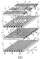
- Figure 1 shows in exploded view, as shown by arrows 7, a first embodiment of a component connection device according to the invention.
- This device comprises four electrically insulating strips 1, 2, 3 and 4 stacked, on each of which are produced, for example by screen printing, electrically conductive tracks 11, 21; 31 and 41 these tracks are located on those of the faces of the lamellae 1, 2, 3 and 4 which are oriented on a given side, as for example towards the top of the device which is, in FIG. 1, on the side of the lamella 1.
- the tracks of a given lamella are substantially rectilinear and parallel to each other.
- the tracks of two adjacent strips are substantially perpendicular: in a geographical reference 5 comprising the four cardinal points, the tracks 11 and 31 of the strips 1 and 3 are for example oriented in the east-west direction (E / O) the tracks 21 and 41 of the slats 2 and 4 are then oriented in the north-south direction (N / S).
- Holes 6, substantially perpendicular to the stack of lamellae connect tracks belonging to lamellae 2, 3 or 4 to zones on the free face of lamella 1, as shown diagrammatically by arrows 8 and 9: in FIG. 1, eight holes connect tracks of the coverslip 2 to the coverslip 1 (as indicated by arrow 8) and four holes connect tracks of the coverslip 3 to the coverslip 1 (as indicated by arrow 9).
- the device of FIG. 1 is intended to receive, on the side of the strip 1, a component whose connection zones are for example arranged according to a substantially regular grid Q: the strip 1 has for this purpose either ends 12 of tracks 11 or or the ends 16 of the holes 6 placed along substantially the same grid Q; these ends 12 or 16 of tracks or holes constitute connection zones for a component which are for example welded to the connection zones of the component: for this purpose the holes 6 are for example filled with an electrically conductive material (as for example a metal) the surfaces of these solid holes thus constituting the ends 16 of holes 6.
- an electrically conductive material as for example a metal
- the grid Q of the zones for the connection of a component of the device fixes the number and distribution of the tracks of the strip 1 which are connected to the ends 12 and of the tracks of the other strips which are connected to holes 6.
- the number and the distribution of the other tracks depend on the application of the device.
- the filling of the holes 6 with an electrically conductive material also provides a function of mechanical assembly of the strips which are electrically connected to the free face of the strip 1; in the case of Figure 1, such a filling assembles the slats 1, 2 and 3; the strips not connected to the free face of the strip 1, like the strip 4 of FIG. 1, are assembled with the other strips for example by gluing.
- the filling of the holes 6 also ensures heat evacuation within the device.
- the lamella 4 of the device of FIG. 1 makes it possible to ensure a "direct" signal transmission, that is to say without passing through the component connected to the device in the manner previously described: the device is in fact intended to be inserted in an assembly, such as in a functional module such as that described in the following, and it may be necessary to produce tracks 40 passing directly through the device.
- the number of strips of the device therefore depends on the application of this device.
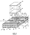
- FIG. 2 illustrates more precisely the operation of the device of FIG. 1: this in fact represents the device of FIG. 1 assembled, as well as a component 50, shown separated from the connection device as indicated by the dotted lines. Due to the respective sizes of the connection zones of the component 50 (not shown in FIG. 2) and of the zones for the connection 12 and 16 of the connection device (previously described), it may be necessary to interpose between the component 50 and the device for connecting the interconnection and fixing means 60; this is in particular the case when the component is an integrated circuit: the fineness of production of the pads of the integrated circuit is then much greater than that which can be achieved during the production of a connection device according to the 'invention.
- interconnection and fixing means 60 consist, for example, of a strip, the two faces 65 and 61 of which are respectively situated against the face 56 of the component which has connection zones and against the free face of the strip 1.
- These two faces 65 and 61 each have connection zones (not shown in FIG. 2) of fineness of intermediate embodiment between that of the connection zones of the component and that of the ends 12 of the tracks 11 or of the ends 16 of holes 6.
- the zones of connection of the faces 65 and 61 are electrically connected by paths passing through the lamella 60. Preferably, at least part of these paths ensures a displacement substantially parallel to the faces 65 and 61.
- the connection zones of the faces 65 and 61 are for example welded respectively to those of component 50 and to the ends 12 or 16 of tracks 11 or holes 6, which also provides mechanical fixing between the component 50, the strip 60, and the connection device.
- the interconnection and fixing means 60 consist of a known interconnection device such as that described in EP-A-0353114: the faces 65 and 61 shown in FIG. 2 are then respectively the first face and the second face of the first variant (comprising a strip) of the known interconnection device, or else the first face of the first strip and the second face of the nth strip of the second variant (comprising n strips) of the known interconnection device.
- Signals can therefore be transmitted in the directions indicated by the arrows 100 between the component 50 and the outside, or else pass directly through the component, as explained above, in the direction indicated by the arrows 200, that is to say , in the example of Figures 1 and 2, in the north-south direction.
- Figures 3 and 4 respectively represent a first and a second section of an embodiment of a functional module according to the invention, comprising a plurality of connection devices according to the invention such as, for example, that of Figures 1 and 2.
- the section plane of Figure 4 is indicated in Figure 3 by the arrows AA.
- the section plane of Figure 3 is identified by arrows B-B in Figure 4.
- Figures 3 and 4 are described simultaneously.
- connection devices 91 for example twelve connection devices 91.
- a component 50 for example by interconnection and fixing means 60 such as those mentioned in the description of FIG. 2.
- connection devices 91 are juxtaposed at the bottom of a box 81, a side wall 71 of which consists for example of a connector capable of ensuring an electrical connection with the outside.
- the box also contains the components 50 and the interconnection and fixing means 60. It includes a cover 72 consisting for example of a plate of a heat conductive material, called cold plate in the following: this plate provides a heat removal function from the functional module and stiffening of this functional module.
- compression means 92 comprising for example springs and known in themselves.
- the components 50 are substantially square strips; the interconnection means 60, and the connection devices 91 are also substantially square; the dimensions of the components 50 are substantially the same as those of the interconnection means 60 and are smaller than those of the connection devices 91; spaces 93 are thus left free inside the box; some of these free spaces 93 can for example be used to house channels within which a heat transfer fluid circulates; these channels are preferably in contact with the cold plate 72, and improve the evacuation of heat outside the functional module. In order to evacuate even more heat, it is also possible to spread a heat-conducting material in the free spaces not containing channels 93 in this case, the cold plate 72 closes the functional module in a sealed manner.
- the components 50 are integrated circuits, and each of these is connected to a capacitor 51 providing a decoupling function, such as for example a multilayer capacitor, known per se to those skilled in the art.
- a capacitor 51 has for example the shape of a substantially square strip and preferably has substantially the same dimensions as the integrated circuit 50.
- the capacitor 51 is placed in the box 81 against the face 57 of the integrated circuit 50 (which is opposite to the face 56 carrying connection zones and situated against the interconnection and fixing means 60).
- the capacitor 51 and the integrated circuit 50 are for example interconnected and fixed in the manner described in FR-A-2638894.
Landscapes
- Engineering & Computer Science (AREA)
- Microelectronics & Electronic Packaging (AREA)
- Manufacturing & Machinery (AREA)
- Combinations Of Printed Boards (AREA)
- Wire Bonding (AREA)
Claims (16)
Applications Claiming Priority (2)
| Application Number | Priority Date | Filing Date | Title |
|---|---|---|---|
| FR8816214A FR2640457B1 (fr) | 1988-12-09 | 1988-12-09 | Dispositif de raccordement de composants et module fonctionnel l'utilisant |
| FR8816214 | 1988-12-09 |
Publications (2)
| Publication Number | Publication Date |
|---|---|
| EP0378016A1 EP0378016A1 (de) | 1990-07-18 |
| EP0378016B1 true EP0378016B1 (de) | 1992-04-08 |
Family
ID=9372767
Family Applications (1)
| Application Number | Title | Priority Date | Filing Date |
|---|---|---|---|
| EP89403360A Expired - Lifetime EP0378016B1 (de) | 1988-12-09 | 1989-12-05 | Anordnung zum Anschluss von Bauteilen und derartige Anordnungen enthaltendes funktionelles Modul |
Country Status (5)
| Country | Link |
|---|---|
| US (1) | US5101323A (de) |
| EP (1) | EP0378016B1 (de) |
| DE (1) | DE68901179D1 (de) |
| FR (1) | FR2640457B1 (de) |
| HK (1) | HK71494A (de) |
Families Citing this family (11)
| Publication number | Priority date | Publication date | Assignee | Title |
|---|---|---|---|---|
| US5165166A (en) * | 1987-09-29 | 1992-11-24 | Microelectronics And Computer Technology Corporation | Method of making a customizable circuitry |
| EP0516866A1 (de) * | 1991-05-03 | 1992-12-09 | International Business Machines Corporation | Modulare mehrschichtige Verbindungsstruktur |
| US5233500A (en) * | 1992-06-01 | 1993-08-03 | Conductus, Inc. | Package for cascaded microwave devices |
| US5244395A (en) * | 1992-07-29 | 1993-09-14 | Motorola, Inc. | Circuit interconnect system |
| US5530288A (en) * | 1994-10-12 | 1996-06-25 | International Business Machines Corporation | Passive interposer including at least one passive electronic component |
| US5789807A (en) * | 1996-10-15 | 1998-08-04 | International Business Machines Corporation | On-chip power distribution for improved decoupling |
| US5801597A (en) * | 1997-02-05 | 1998-09-01 | Lucent Technologies Inc. | Printed-circuit board-mountable ferrite EMI filter |
| US6111756A (en) * | 1998-09-11 | 2000-08-29 | Fujitsu Limited | Universal multichip interconnect systems |
| US6534872B1 (en) | 1998-10-13 | 2003-03-18 | Sun Microsystems, Inc. | Apparatus and system with increased signal trace routing options in printed wiring boards and integrated circuit packaging |
| JP4063533B2 (ja) * | 2001-12-10 | 2008-03-19 | 日本碍子株式会社 | フレキシブル配線板 |
| US7118393B1 (en) * | 2005-08-08 | 2006-10-10 | Tyco Electronics Corporation | Bonded elastomeric connector |
Family Cites Families (13)
| Publication number | Priority date | Publication date | Assignee | Title |
|---|---|---|---|---|
| DE1069236B (de) * | 1956-09-04 | 1959-11-19 | ||
| US3029495A (en) * | 1959-04-06 | 1962-04-17 | Norman J Doctor | Electrical interconnection of miniaturized modules |
| DE2611871A1 (de) * | 1975-03-26 | 1976-10-07 | Honeywell Inf Systems | Elektrische schaltungsbaugruppe in mehrschichtbauweise und verfahren zu deren herstellung |
| US4202007A (en) * | 1978-06-23 | 1980-05-06 | International Business Machines Corporation | Multi-layer dielectric planar structure having an internal conductor pattern characterized with opposite terminations disposed at a common edge surface of the layers |
| GB2033668B (en) * | 1978-11-11 | 1983-01-06 | Ferranti Ltd | Circuit assemblies |
| US4434321A (en) * | 1981-02-09 | 1984-02-28 | International Computers Limited | Multilayer printed circuit boards |
| US4581679A (en) * | 1983-05-31 | 1986-04-08 | Trw Inc. | Multi-element circuit construction |
| US4535388A (en) * | 1984-06-29 | 1985-08-13 | International Business Machines Corporation | High density wired module |
| FR2593346B1 (fr) * | 1986-01-17 | 1990-05-25 | Nec Corp | Substrat de cablage utilisant une ceramique comme isolant |
| US4755866A (en) * | 1987-02-27 | 1988-07-05 | United Technologies Corporation | Electronic circuit module |
| US4942497A (en) * | 1987-07-24 | 1990-07-17 | Nec Corporation | Cooling structure for heat generating electronic components mounted on a substrate |
| DE8801970U1 (de) * | 1988-02-16 | 1988-04-14 | Bopp, Martin, 6086 Riedstadt | Kontaktvorrichtung |
| US4878846A (en) * | 1988-04-06 | 1989-11-07 | Schroeder Jon M | Electronic circuit chip connection assembly and method |
-
1988
- 1988-12-09 FR FR8816214A patent/FR2640457B1/fr not_active Expired - Lifetime
-
1989
- 1989-12-05 DE DE8989403360T patent/DE68901179D1/de not_active Expired - Fee Related
- 1989-12-05 EP EP89403360A patent/EP0378016B1/de not_active Expired - Lifetime
- 1989-12-06 US US07/446,808 patent/US5101323A/en not_active Expired - Lifetime
-
1994
- 1994-07-21 HK HK71494A patent/HK71494A/xx not_active IP Right Cessation
Also Published As
| Publication number | Publication date |
|---|---|
| DE68901179D1 (de) | 1992-05-14 |
| FR2640457B1 (fr) | 1991-01-25 |
| US5101323A (en) | 1992-03-31 |
| EP0378016A1 (de) | 1990-07-18 |
| HK71494A (en) | 1994-07-29 |
| FR2640457A1 (fr) | 1990-06-15 |
Similar Documents
| Publication | Publication Date | Title |
|---|---|---|
| EP0378016B1 (de) | Anordnung zum Anschluss von Bauteilen und derartige Anordnungen enthaltendes funktionelles Modul | |
| EP0595735B1 (de) | Sensor für eine richtungsabhängige physikalische Grösse | |
| CA2233979A1 (en) | Fabrication of thermoelectric modules and solder for such fabrication | |
| EP1550361B1 (de) | Dreidimensionales elektronisches modul | |
| EP0310463A1 (de) | Gehäuse für einen hochintegrierten Schaltkreis | |
| FR2688629A1 (fr) | Procede et dispositif d'encapsulation en trois dimensions de pastilles semi-conductrices. | |
| WO1992010853A1 (fr) | Procede et dispositif d'interconnexion de circuits integres en trois dimensions | |
| US4206470A (en) | Thin film interconnect for multicolor IR/CCD | |
| FR2512315A1 (fr) | Ebauche de circuit electrique multicouche et procede de fabrication de circuits multicouches en comportant application | |
| US5561593A (en) | Z-interface-board | |
| FR2645681A1 (fr) | Dispositif d'interconnexion verticale de pastilles de circuits integres et son procede de fabrication | |
| EP1156347A1 (de) | Detektorhalter für ionisierende Strahlung | |
| EP0072759B1 (de) | Elektronischer Modul für Karte für automatische Transaktionen und Karte versehen mit einem solchen Modul | |
| FR2776462A1 (fr) | Module de composants electroniques de puissance | |
| EP3351069B1 (de) | Kompaktes elektronisches system und vorrichtung mit solch einem system | |
| US4341012A (en) | Pyroelectric detector arrays | |
| EP0166634A1 (de) | Einrichtung zur Verteilung von elektrischen Potentialen, und eine solche Einrichtung enthaltendes Gehäuse für elektronische Komponenten | |
| EP1035573A1 (de) | Elektrisches Leistungsbauelement auf einen Träger gelötet und Montierungsverfahren dafür | |
| FR2630859A1 (fr) | Boitier ceramique multicouches a plusieurs puces de circuit-integre | |
| FR2579022A1 (fr) | Ensemble a circuits electroniques comprenant au moins un element a circuits integres | |
| EP0844666A1 (de) | Zusammenbau elektronischer Moduln mit mehreren Ebenen | |
| EP0629000B1 (de) | Integrierter Schaltungszusammenbau von höher Dichte und Betriebssicherheit und Herstellungsverfahren | |
| FR2551618A1 (fr) | Procede de fabrication d'un circuit imprime a couches enterrees et circuit imprime obtenu par un tel procede | |
| EP0431106B1 (de) | Verkapselte elektronische schaltung mit chip auf einer quadrierten zone mit leiterpodesten | |
| FR2699039A1 (fr) | Carte électronique à substrat multicouche. |
Legal Events
| Date | Code | Title | Description |
|---|---|---|---|
| PUAI | Public reference made under article 153(3) epc to a published international application that has entered the european phase |
Free format text: ORIGINAL CODE: 0009012 |
|
| AK | Designated contracting states |
Kind code of ref document: A1 Designated state(s): DE GB IT NL |
|
| 17P | Request for examination filed |
Effective date: 19901219 |
|
| 17Q | First examination report despatched |
Effective date: 19910809 |
|
| GRAA | (expected) grant |
Free format text: ORIGINAL CODE: 0009210 |
|
| AK | Designated contracting states |
Kind code of ref document: B1 Designated state(s): DE GB IT NL |
|
| ITF | It: translation for a ep patent filed | ||
| REF | Corresponds to: |
Ref document number: 68901179 Country of ref document: DE Date of ref document: 19920514 |
|
| GBT | Gb: translation of ep patent filed (gb section 77(6)(a)/1977) | ||
| PLBE | No opposition filed within time limit |
Free format text: ORIGINAL CODE: 0009261 |
|
| STAA | Information on the status of an ep patent application or granted ep patent |
Free format text: STATUS: NO OPPOSITION FILED WITHIN TIME LIMIT |
|
| 26N | No opposition filed | ||
| REG | Reference to a national code |
Ref country code: GB Ref legal event code: IF02 |
|
| PGFP | Annual fee paid to national office [announced via postgrant information from national office to epo] |
Ref country code: GB Payment date: 20021204 Year of fee payment: 14 |
|
| PGFP | Annual fee paid to national office [announced via postgrant information from national office to epo] |
Ref country code: DE Payment date: 20021205 Year of fee payment: 14 |
|
| PGFP | Annual fee paid to national office [announced via postgrant information from national office to epo] |
Ref country code: NL Payment date: 20021227 Year of fee payment: 14 |
|
| PG25 | Lapsed in a contracting state [announced via postgrant information from national office to epo] |
Ref country code: GB Free format text: LAPSE BECAUSE OF NON-PAYMENT OF DUE FEES Effective date: 20031205 |
|
| PG25 | Lapsed in a contracting state [announced via postgrant information from national office to epo] |
Ref country code: NL Free format text: LAPSE BECAUSE OF NON-PAYMENT OF DUE FEES Effective date: 20040701 Ref country code: DE Free format text: LAPSE BECAUSE OF NON-PAYMENT OF DUE FEES Effective date: 20040701 |
|
| GBPC | Gb: european patent ceased through non-payment of renewal fee |
Effective date: 20031205 |
|
| NLV4 | Nl: lapsed or anulled due to non-payment of the annual fee |
Effective date: 20040701 |
|
| PG25 | Lapsed in a contracting state [announced via postgrant information from national office to epo] |
Ref country code: IT Free format text: LAPSE BECAUSE OF NON-PAYMENT OF DUE FEES;WARNING: LAPSES OF ITALIAN PATENTS WITH EFFECTIVE DATE BEFORE 2007 MAY HAVE OCCURRED AT ANY TIME BEFORE 2007. THE CORRECT EFFECTIVE DATE MAY BE DIFFERENT FROM THE ONE RECORDED. Effective date: 20051205 |