EP0377218A2 - Overedge seaming machine, especially for carpets - Google Patents
Overedge seaming machine, especially for carpets Download PDFInfo
- Publication number
- EP0377218A2 EP0377218A2 EP89124060A EP89124060A EP0377218A2 EP 0377218 A2 EP0377218 A2 EP 0377218A2 EP 89124060 A EP89124060 A EP 89124060A EP 89124060 A EP89124060 A EP 89124060A EP 0377218 A2 EP0377218 A2 EP 0377218A2
- Authority
- EP
- European Patent Office
- Prior art keywords
- thread
- sewing machine
- yarn
- needle
- sewing
- Prior art date
- Legal status (The legal status is an assumption and is not a legal conclusion. Google has not performed a legal analysis and makes no representation as to the accuracy of the status listed.)
- Granted
Links
- 238000004826 seaming Methods 0.000 title 1
- 239000000463 material Substances 0.000 claims abstract description 78
- 238000009958 sewing Methods 0.000 claims abstract description 55
- 238000005520 cutting process Methods 0.000 claims abstract description 23
- 230000007246 mechanism Effects 0.000 claims description 30
- 230000033001 locomotion Effects 0.000 claims description 20
- 230000015572 biosynthetic process Effects 0.000 claims description 12
- 238000009964 serging Methods 0.000 claims description 9
- 238000003825 pressing Methods 0.000 claims description 6
- 238000009957 hemming Methods 0.000 claims description 4
- 238000007688 edging Methods 0.000 claims description 2
- 230000001419 dependent effect Effects 0.000 claims 1
- 230000010355 oscillation Effects 0.000 claims 1
- 230000032258 transport Effects 0.000 description 28
- 235000004443 Ricinus communis Nutrition 0.000 description 3
- 240000000528 Ricinus communis Species 0.000 description 2
- 238000010276 construction Methods 0.000 description 2
- 230000006378 damage Effects 0.000 description 2
- 238000000034 method Methods 0.000 description 2
- 230000009467 reduction Effects 0.000 description 2
- 239000002699 waste material Substances 0.000 description 2
- 208000012266 Needlestick injury Diseases 0.000 description 1
- 229910000639 Spring steel Inorganic materials 0.000 description 1
- 208000027418 Wounds and injury Diseases 0.000 description 1
- 230000006978 adaptation Effects 0.000 description 1
- 238000005452 bending Methods 0.000 description 1
- 230000033228 biological regulation Effects 0.000 description 1
- 239000003086 colorant Substances 0.000 description 1
- 238000005034 decoration Methods 0.000 description 1
- 238000013461 design Methods 0.000 description 1
- 238000011161 development Methods 0.000 description 1
- 230000018109 developmental process Effects 0.000 description 1
- 238000006073 displacement reaction Methods 0.000 description 1
- 230000000694 effects Effects 0.000 description 1
- 239000000945 filler Substances 0.000 description 1
- 230000005764 inhibitory process Effects 0.000 description 1
- 208000014674 injury Diseases 0.000 description 1
- 238000003780 insertion Methods 0.000 description 1
- 230000037431 insertion Effects 0.000 description 1
- 238000004519 manufacturing process Methods 0.000 description 1
- 239000002184 metal Substances 0.000 description 1
- 230000008569 process Effects 0.000 description 1
- 238000012545 processing Methods 0.000 description 1
- 238000011144 upstream manufacturing Methods 0.000 description 1
- 238000009941 weaving Methods 0.000 description 1
- 238000004804 winding Methods 0.000 description 1
Images


Classifications
-
- D—TEXTILES; PAPER
- D05—SEWING; EMBROIDERING; TUFTING
- D05B—SEWING
- D05B1/00—General types of sewing apparatus or machines without mechanism for lateral movement of the needle or the work or both
- D05B1/08—General types of sewing apparatus or machines without mechanism for lateral movement of the needle or the work or both for making multi-thread seams
- D05B1/18—Seams for protecting or securing edges
- D05B1/20—Overedge seams
-
- D—TEXTILES; PAPER
- D05—SEWING; EMBROIDERING; TUFTING
- D05B—SEWING
- D05B37/00—Devices incorporated in sewing machines for slitting, grooving, or cutting
- D05B37/04—Cutting devices
- D05B37/06—Cutting devices with oscillating tools
-
- D—TEXTILES; PAPER
- D05—SEWING; EMBROIDERING; TUFTING
- D05D—INDEXING SCHEME ASSOCIATED WITH SUBCLASSES D05B AND D05C, RELATING TO SEWING, EMBROIDERING AND TUFTING
- D05D2203/00—Selection of machines, accessories or parts of the same kind
-
- D—TEXTILES; PAPER
- D05—SEWING; EMBROIDERING; TUFTING
- D05D—INDEXING SCHEME ASSOCIATED WITH SUBCLASSES D05B AND D05C, RELATING TO SEWING, EMBROIDERING AND TUFTING
- D05D2303/00—Applied objects or articles
- D05D2303/02—Tape
-
- D—TEXTILES; PAPER
- D10—INDEXING SCHEME ASSOCIATED WITH SUBLASSES OF SECTION D, RELATING TO TEXTILES
- D10B—INDEXING SCHEME ASSOCIATED WITH SUBLASSES OF SECTION D, RELATING TO TEXTILES
- D10B2503/00—Domestic or personal
- D10B2503/04—Floor or wall coverings; Carpets
Definitions
- the invention relates to a sewing machine, in particular for edging or hemming materials such as the edges of floor coverings or the like.
- sewing machines which are also referred to as binding machines or hemming machines
- binding machines or hemming machines are in particular to cleanly and securely bind the edges of carpets or the like, which are in the form of rolls and are cut to the size of use. It is indicated by the invention strives for the machine to be relatively easy to handle despite high performance and, if possible, also to be used in a mobile manner, because, especially when chaining very large areas, the space required to guide the entire piece of material past the machine would become too large.
- the machine according to the invention has a drive, a sewing mechanism with transport means for the material relative to the sewing mechanism, a needle mechanism and a loop formation mechanism and a thread feed to the needle and loop formation mechanism.
- the sewing mechanism which is preferably designed to form a two-thread overlock seam, has a holding gripper which retains a thread loop during the formation of an overlock loop. This preferably engages near the path of movement of the needle from below into the thread coming from a yarn gripper.
- a thread runs through the stitch holes, which only has a holding function and has no essential decorative or covering tasks.
- a very strong, high quality and thin thread can be used there, for example a thread.
- This thread is therefore called thread in the following, while thread is the thread that runs from the upper to the lower stitch row around the outer edge and, if necessary, an intermediate tuck belt and has the actual covering and decoration function.
- thread is also advantageously possible to use two yarn threads from two different bobbins together as yarn, for example to better match the color of the carpet by mixing two yarn colors in the wrapping. Accordingly, several threads are to be understood as “yarn" in the following.
- the thread is introduced by the needle, which forms loops on the top and bottom of the material with a thread threaded into a yarn gripper, an overlocking looper taking over the thread coming from the yarn gripper and in the form of a loop around the material edge the top brings.
- the thread could be the twisted loop formed on the underside in the direction of the mate Pull the edge of the rial while the overlock hook pulls yarn to form the long overlock loop.
- a holding gripper engages in the part of the yarn loop remaining on the underside of the material and holds it back as long as the usual gripper pulls the loop upwards.
- the gripper is then pulled out and the twine loop can tighten the yarn so that the lower binding formed by the yarn lies directly on the row of stitches and does not run offset to the edge. In this way, the thread tension can also be reduced because the thread no longer has to actively counteract this tendency to offset.
- the three grippers can all be arranged as oscillating grippers and can be moved mostly harmoniously and continuously, which is possible by simple crank, eccentric or lever movements. Sliding movements and other movements that are unfavorable in terms of manufacture and wear can be largely avoided. Only the holding gripper normally has a standstill phase, which can be derived from a lever movement with a simple stop.
- the grippers are designed so that their overall size is small compared to the paths they travel and their concentration in a small space allows.
- the base part receiving the looper ie the space under the material receiving table, as flat as possible, in order to have to lift the carpet only slightly when the device is mobile on partially self-steering castors, advantageously to the sewing machine to drive along the edge of the lying carpet while chaining.
- a thread guide channel through which the thread runs in opens into a position in which the thread gripper assumes a defined position, for example marked on the handwheel, for example the bottom dead center of the sewing mechanism. This aligns a threading channel, which, like the thread guide channel, ends outside the machine, so that through these two channels and the eye in between, a threading tool, e.g. in the form of a wire with a hook, passed through it and a thread can be pulled through.
- a threading tool e.g. in the form of a wire with a hook
- a sewing machine of the type mentioned at the outset can have a cutting device for the material, by means of which the corners, which usually run at right angles from the cut, can be provided with a radius suitable for weaving.
- a vertically oscillating knife is provided in front of the needle position, the cutting position of which is aligned with the edge.
- a continuous drive of this knife would not directly damage a carpet cut because it would only "scrape" along the edge, but would be unfavorable in terms of wear, volume, etc. It is therefore provided in this feature of the invention that the knife drive can be switched on and off by a knife switch-on device during the operation of the sewing mechanism.
- the knife switch-on device can preferably be actuated automatically depending on the material, for example by means of a photo cell which automatically starts the cutting device when a corner comes, ie, when the photocell placed in front of the needle position receives light from a lamp provided on the machine, while it is normally covered by the carpet during the wrapping of straight edges.
- the knife drive for example a double-sided cam, which advantageously enables two knife strokes per stitch, can run continuously, while the actual knife drive member, for example a lever interacting therewith, from a detent actuated by a magnet in the Normal position is kept out of engagement with the actuator.
- the invention provides for relieving the means of transport when cornering.
- Such relief is usually carried out manually by means of a lifting lever for the pressure foot, which presses the material against an oscillating, movable toothed rack arranged in the base part.
- a lifting lever for the pressure foot, which presses the material against an oscillating, movable toothed rack arranged in the base part.
- Such a lifting device is also provided.
- relief means are provided which automatically relieve the pressure of the pressure foot on the transport toothed strip from the spring force normally acting thereon when the cutting device is switched on.
- a particularly preferred embodiment is one in which this is done by a one-way clamping device which can be actuated by the switch-on device and which actuates the pressure foot when it is actuated is only possible to move upwards, but is stuck against a movement downwards. This prevents the pressure foot, which is normally raised and lowered a little by the lifting movement of the transport terminal strip, with each stroke, from moving back down under the spring force, so that it remains in the uppermost position of this cycle, which depends on the material thickness. In this position, with automatic adaptation to the material thickness, the covering can be rotated relative to the carpet without difficulty or injury, without losing the contact pressure required for a certain transport support and guidance.
- a guide stop can also be provided, which normally guides the edge of the material, but can be swiveled away for linking inside corners.
- a feed roller can preferably be attached to it, which runs in front of the edge of the material guide table and is so inclined that it pushes the material in the direction of the guide stop. This is particularly important if only narrow strips, for example as skirting boards, are to be linked.
- the invention also relates to a sewing machine in which the thread feeder contains at least one thread tensioner which guides the thread between two surfaces.
- One can be a roller that can be rotated with the thread, the thread being pressed on by a pressure part that is bent, for example, from sheet metal.
- Kin ken threadline knots
- Such kink formation can result, for example, from the withdrawal of the threads from an end face of a bobbin, which applies a 360 ° twist to the thread with each turn.
- the pressure part By attaching a thread eyelet to the pressure part, the pressure part can be self-regulating, ie when the thread feed tension is high, the pressure part, which is pressed in in an elastically adjustable manner, is lifted off and thus reduces the tension that is additionally applied by it. If this eyelet is attached to the inlet side of the thread tensioner, the thread tensioner reacts to resistances in the upstream thread feed, unaffected by the thread which is discontinuously withdrawn from the sewing mechanism.
- the invention also relates to a feature according to which the thread feed is designed in such a way that a thread looping around an eyelet after a thread loosening can no longer pinch itself, which has previously mostly led to thread breakage. If the eyelet is constructed in such a way that its connection to a machine part, at least in the area of the eyelet, is not narrower than the outer eyelet limit, then the thread automatically slips on it when it comes under tension, without tightening by pinching two parts of the thread lying one above the other.
- the invention provides a sewing machine for hemming or binding, which, despite great performance and the possibility of working on floor coverings of any thickness, is portable and with great reliability and high performance can also be used in rough construction site operations.
- the part receiving the thread bobbins or idler tape rolls can be folded up for transport. This can also accommodate castor wheels similar to furniture castors, while a fixed roll can be provided in the sewing area which runs in the sewing direction.
- the sewing machine 11 shown in the drawings has a lower, relatively flat base part 12 and a tower or column-like drive part 13 (FIGS. 1 and 2) projecting upwards therefrom, which comprises the drive motor 14 (FIG. 3) and the essential drive mechanisms .
- a holder 24 of a twisted bobbin 25 is provided on the removable housing 26 of the drive part.
- the housing 26 is provided with a handle 27 for transportation.
- the yarn 28 and twine 29 coming from the corresponding bobbins 21, 25 runs Via eyelets 30, which will be described later, on a thread unwinding frame 31, which can also be swiveled or removed and resilient to compensate for tension, and is then fed from above via eyelets 32 to a thread tensioner 33, which are also attached to the housing 26.
- the thread tensioners 33 each contain a base plate 34, on which a roller 36 is rotatably mounted about a horizontal axis 35 (FIG. 1).
- a pressure part 37 bent from spring steel sheet and pivotable about an axis 38 lies flat against the lateral surface 39, namely over an angle of approximately 90 ° or above.
- At the end of the pressure part opposite the axis there is a guide eyelet 40 for the thread 28 and 29 respectively.
- the pressure part 37 is pressed against the roll by means of a set screw and a spring guided therein, so that the thread is pressed flat between them. Since the roller 36 can rotate when the thread is pulled through, the pressing force of the pressing part 37 can be relatively high with a comparable tensioning or braking effect of the thread tensioner.
- thread twist before or in the thread tensioner prevents the thread from overturning (kinking) or runs through.
- An inhibition in the thread running direction in front of the thread tensioner 33 leads to a pressure reduction of the pressure part 37 by an upward pull on the eyelet 40, so that there is an automatic tension control or regulation.
- the thread 29 runs after wrapping around the roller 36 by 130 to 180 ° via a tension compensation spring 42 and an eyelet 43 to a thread lifter 44 which is oscillatingly driven together with the needle and relieves the eye 45 in the needle 46 of the thread pulling work (Fig. 3).
- the sewing machine 11 is driven by a main shaft 48 (FIG. 3) which is driven by the motor 14 via a suitable gear, here a two-stage round belt reduction gear.
- a handwheel 29 arranged on the main shaft 48 outside the housing 26 enables fine adjustment, for example for threading.
- Two eccentrics 51 for driving the material transport means 52 are arranged on the main shaft 48 mounted in a base frame 50.
- a crank mechanism is attached, which consists of two disk-like crank webs 53, 54, a crank pin 55 connecting them and a freely projecting crank pin 56.
- the inner crank arm 53 is designed as a drive cam of a cutting device with two opposing cam lobes on the circumference (FIG. 8).
- the crank pin 56 actuates, via a connecting rod 57, the drive of the needle rod 59, which is guided in the longitudinal direction and is slightly inclined backwards relative to the material running direction 58.
- the connecting rod 57 engages on this via a clamping block 60 clamped on the needle rod 59, which also carries the thread lifter 44 , which protrudes through a slot in the housing 26 to the outside.
- the loop formation mechanism 61 arranged in the base part 12, which is described with reference to FIGS. 3 to 6, is driven by the crank pin 55 via the connecting rod 62. It swings an oscillating shaft 64 back and forth via a drive lever 63, on which a yarn gripper 65 and an actuating lever 68 are attached in a rotationally fixed manner.
- the yarn gripper 65 has an arcuate or ring segment shape in its outer portion, which carries a yarn eye 69 near its front end and is connected to the shaft 64 via a radial arm.
- An overlocking gripper 66 is pivotally mounted about a shaft 70 and is driven from the lever 63 via a push rod 71. It has a circular arc shape, at one end of which the shaft 70 is attached, while the other end is provided with a gripper fork 150.
- a holding gripper 67 with a holding finger 151 at its front end is pivotable about a shaft 72 and is driven by the lever 68 via a lever arm 73.
- a stop lever 74 interacts with a housing stop 75, against which it is pressed under the force of a spring 76, to limit the movement of the holding gripper 67.
- the transport means 52 for the material to be linked 80 (FIG. 9) contain a transport toothed rack 81, which runs through an oval movement path 82 indicated by dash-dotted lines in FIG. 9, so that in each case on a transport stroke in which the toothed rack is above the level of the material support table 83 moves in the transport direction 58, a return stroke takes place in the position lowered below the plane 83.
- This is effected via the connecting rods 84, 85 connected to the eccentrics 51.
- the connecting rod 84 pivots a lever 86 by being articulated on a threaded bushing 87 which can be displaced on an adjusting threaded rod 88 provided with a very steep external thread by means of an adjusting knob 89.
- the lever pivots about the axis 90, while at its other end a lever 91 is articulated, which carries the toothed rack 81 at its other end.
- the connecting rod 85 engages at some distance from the link 92 to the lever 86.
- FIG. 8 shows a cutting device 93 and a pressure foot 94, which presses the material obliquely from above against the transport toothed rack 81 (see also FIG. 1).
- This pressure foot 94 is displaceably guided parallel to the needle axis 95 and is pressed down by means of a spring 96 so that its bow-shaped foot part 97, which grips around the needle in a fork-like manner, is pressed downward against the material.
- the pressure foot With a hand lever 98, the pressure foot can be raised and, if the in the fol Automatic cutting device described above is switched on and effective, can also be locked in the raised position.
- a clamping plate 100 engages, which together with a lever 101 shown in broken lines can be pivoted about an axis 102.
- the pivoting takes place via a leaf spring 103 attached to the lever, which pivots the lever 101 counterclockwise from an electromagnet 104 when it is tightened.
- the pressure foot 94 is guided at its upper end in a sliding guide of its rod 99 in the base frame, it is guided in a substantially vertically movable manner below by means of a rocker 105.
- the lever 101 has a downwardly extending arm 106, the inclined end surface of which can engage the free end of a lever-like knife drive member 78, which is arranged pivotably about an axis 107 on the base frame and is articulated on a knife 108.
- the knife is located on a substantially vertically guided knife rod 109, on which a spring 110 engages, which tries to pull the knife into its upper end position.
- the double cam-like crank arm 53 can cooperate with the knife drive member 78 to oscillate the knife with two strokes per revolution of the main shaft 48.
- the knife has an inclined cutting edge 111 which is directed counter to the material transport direction 58 and downwards, at the end of which a guide lug 112 extends downward. It interacts with a counter knife 113 (FIG. 10), the guide lug also keeping the knife in its upper position aligned with the counter knife 113 attached to the material support table 83.
- the counter knife 113 is arranged on an interchangeable needle plate 114 inserted in the material support table 83 and is arranged at a small angle obliquely to the material running direction 58. This takes into account the cutting conditions during corner rounding, in which the needle 46 usually determines the axis of rotation.
- a guide nose 115 is provided which is directed in the material running direction 58 and guides the material edge and around which the yarn 28 is placed when forming an overlocking loop before it slips off during further transport and is tightened.
- the filler belt 23 is fed between the material edge and the guide nose 115 if it is used.
- a photo sensor 117 is arranged in the material support table in the direction of the material at a distance from the needle position and also at a distance from a guide plate 116 which can be swiveled away and which can receive light from a lamp 118 which is designed as working light in the sewing area.
- the photo sensor 117 belongs to a switch-on device which contains a control unit in the electrical control part 119 (FIG. 2) and can control the electromagnet 104 for actuating the cutting device and raising the pressure foot (FIG. 8).
- the automatic cutting system can be selected or switched off manually via a switch 120.
- a feed roller 121 is attached, which lies in front of the beginning of the material support table 83 with its upper edge slightly above its level and the axis of which is so inclined that an object moving on it is pushed against the guide plate 160 at a small angle becomes, in particular, if a pressure roller 122, which can also be swiveled away, resiliently presses the material guided in between onto the feed roller 121.
- the inclined axis 123 of the feed roller 121 continues as a rotatable shaft on the back of the guide plate 116 and carries a pulse generator 124 there, which can contain, for example, a permanent magnet 124 (FIG. 10).
- the eyelet 32 shows a thread guide eyelet 32 on the housing 26.
- the basic principle of the eyelets 30 on the thread unwinding frame 31 is identical.
- the eyelet 32 consists of a loop made of a bare and smooth wire 129 which is on a Base plate 128 is attached with its two ends.
- the opening 130 of the eyelet is surrounded by a ring boundary, which consists of one and a half spiral turns of wire, which lie close together and thus prevent the thread from being jammed between them.
- Two connecting legs 132 connect to the ring boundary 131 and connect the ring boundary 131 to the base plate 128.
- the outer surfaces of these two legs are at a distance from one another which is at least as large as the greatest width of the ring boundary 131. They can run parallel to one another or possibly diverge somewhat from the ring boundary to the base plate.
- the eyelet described prevents a loose thread from looping around the connecting section and then tightening by pinching the yarn sections lying one above the other, which could lead to thread breakage. With this eyelet formation, the thread automatically slips over the ring boundary again when it comes to pull.
- the sewing machine according to the invention works according to the following method:
- thread and thread bobbins 21, 25 can be applied and the threads 28, 29 threaded.
- the course of the thread has already been described.
- a threading tool 158 in the form of a wire with a hook on its front.
- the threading tool 158 can be inserted until it comes out of the outer opening 134 of the Thread guide channel 47 looks out.
- the yarn which can consist of several individual yarns, can then be hooked into the hook and pulled through the yarn guide channel and the eye 69 and the threading channel 133 in one go. After it is removed from the hook, the machine is ready for operation.
- the material 80 to be linked is then brought to the material support table 83, starting from the left in FIG. 1.
- the pressure roller 122 can be swiveled up if it is a larger piece of material.
- the machine can be installed stationary, for example on a table. But it is advantageous, running on its rollers 16 and 17, along the laid out material, which only has to bulge relatively little to get onto the material support table 83, because the base part 12 can be made relatively flat due to the design of the sewing mechanism described .
- the feed roller 121 and the ball guides 127 also ensure smooth running.
- a handle 138 can be attached to the housing 26 by means of a snap fastening 153 and connected to the sewing machine 11 via an electrical plug connection. It can also stroke on a in Fig. 1 Liert indicated extension stem 152 are attached, which in turn can be snapped onto the snap fastener 153. This makes it easier to drive the machine on the ground.
- the edge 135 of the material 80 to be linked runs along the guide plate 116 and is guided under the foot bracket 97 of the pressure foot 94, which for this purpose was set in an upper position by means of the lifting lever 98.
- the pressure foot is then lowered and presses the underside of the material onto the transport rack 81.
- the machine is then gripped by the handle 138 which can be removed for transport and started by means of an operating switch 137 provided in the handle.
- the transport described with reference to FIG. 9 is thereby set in motion and transports the material in the transport direction 58 or pulls the machine along the material edge in the corresponding direction.
- the transport length per stroke, i.e. the stitch length can be set via the adjusting knob 89, which moves the threaded bushing 87, on which the connecting rod 84 engages, on the threaded rod 88 and thus determines the pivoting angle of the lever 86 and thus the longitudinal displacement of the rod 91 and the toothed rack 81.
- the overlocking gripper 66 has pulled a yarn overlocking loop 139 around the material edge 135 with its gripper fork 150 and brought it into a position beyond the needle 46 so that it can pierce the overlocking loop 139.
- the overhand gripper 66 engages past the needle, the needle sticks into the loop, ie behind the front thread of the loop, while the thread remains outside the loop, ie runs past the thread.
- This relates to the illustration chosen in FIGS. 4 to 6, in which the direction of transport of the material (arrow 58) is selected to the viewer.
- the yarn gripper 65 which now pivots again clockwise, passes between the needle and the thread above the eye 45 and, as can be seen in particular in FIG. 6, pulls the yarn through a lower thread loop to form the overlocking loop.
- a yarn guide roller 154 indicated in FIG. 6 and adjoining the mouth of the yarn guide channel 47, facilitates the retraction of the yarn length.
- the overlock loop 139 thus forms between the yarn feeder over the yarn guide channel 47 and a yarn section which connects to the last overlock loop.
- the holding gripper 67 engages in this area and prevents this yarn section (holding loop 140) from being pulled too far in the direction of the edge 135 when the overlock seam is formed. In this position, namely lower thread loop 141 has not yet been tightened, and thus the thread would not lie in the area of the stitch row, but somewhere between it and the edge 35.
- the overlock loop 139 is not pulled directly around the edge 135, but rather around the guide lug 115 (FIG. 10), from which it slips off before the overlock loop is tightened.
- a run-in belt 23 which covers the edge 135, for example to prevent pile parts from sticking out between the yarn loops in the case of very long-pile carpets. Because of the excellent seam formation qualities and the large adjustment range of the stitch lengths, it is also possible to work with a decorative side tape which, for example with monofilament transparent yarn, is only chained with a relatively large stitch spacing.
- the thread feed is very uniform due to the arrangement described and without risk of overvoltage.
- the additional twist in the threads generated by the bobbin winding is compensated for by the thread tensioners described and no additional twist is imposed on the yarn or twine on the inlet side, which could happen with plate thread tensioners as a result of the helical course of the yarn cardels.
- the tension compensation spring 42 together with the thread lifter ensures an even passage of the yarn through the thread tensioner.
- the thread tension does not have to be selected high in the sewing machine, because the holding gripper 67 does not have to be used to hold the lower thread loop in the stitch area by means of high thread tension. The risk of thread breakage is therefore significantly reduced.
- the photo sensor 117 previously covered by the material 80 is released and receives light from the lamp 118. This activates the switch-on device, and the magnet 104, which until then has been de-energized, attracts. He pivots the leaf spring 103 counterclockwise, so that the lever 101 is also pivoted in this direction (Fig. 8). As a result, the clamping plate 100 is pressed with the edges of its hole against the pressure foot rod 99 and clamps it in such a way that it can only be moved upwards but not downwards. Since the material and thus also the pressure foot is periodically raised and lowered by the transport toothed strip 81 during transport, the pressure foot is now only moved upwards and then remains in the upper position.
- the lower lever arm 106 pivots to the right in such a way that the arm of the knife drive member 78, which was previously in contact with it, becomes free and thus the knife 108 and knife rod 109 can be pressed against the curve 53 under the force of the spring 110 and can be moved by this in an oscillating manner.
- the knife therefore works and, with its oblique cutting edge 111 in cooperation with the counter cutting edge 113, cuts off a corner of the material, for example a point which was previously rectangular, in a radius which is not too large but uniform.
- the resulting cutting waste can be discharged through a waste channel 143 (FIGS. 1 and 10) in the base part 12.
- the cutting radius is determined by the fact that the guide plate 116, with its edge 144 pointing in the transport direction 58, lies at a distance from the sewing area, and in particular the needle position. Only when the material corner has passed this edge 144 can the material be rotated relative to the machine. The curve is then immediately linked. After the rounding has ended, the material again covers the photo sensor 117, and the switch-on device deenergizes the magnet 104. As a result, the lever 101 is loaded in the sense of a clockwise rotation, the clamping plate 100 releases the pressure foot rod 99, and the knife actuating element 78 slides along the arm 106 during its pivoting movement and engages under this lever shortly before the dead center and is thus blocked.
- the knife actuating element works into a position where it is no longer moved by the curve 53. So that the knife is blocked in its lower position, so that the cutting edge is sunk and covered.
Landscapes
- Engineering & Computer Science (AREA)
- Textile Engineering (AREA)
- Sewing Machines And Sewing (AREA)
- Treatment Of Sludge (AREA)
Abstract
Die Nähmaschine dient zum Umketteln von Bodenbelägen und ist transportabel ausgebildet, so daß sie außer dem stationären Einsatz auch entlang der zu umkettelnden Materialkante gefahren werden kann. Sie erzeugt eine Zweifaden-Überwendlichnaht und hat eine Schneidvorrichtung mit einem Messer (108) zur Abrundung der Materialecken vor dem Ketteln, die bei Annäherung einer Ecke, von einer Fotozelle (117) gesteuert, automatisch in Gang gesetzt wird.The sewing machine is used for chaining floor coverings and is designed to be transportable, so that it can also be moved along the material edge to be chained in addition to stationary use. It creates a two-thread overlock seam and has a cutting device with a knife (108) for rounding off the material corners before starting the warping, which is automatically started when a corner is approached, controlled by a photocell (117).
Description
Die Erfindung betrifft eine Nähmaschine, insbesondere zum Einfassen bzw. Säumen von Materialien, wie der Kanten von Bodenbelägen oder dgl..The invention relates to a sewing machine, in particular for edging or hemming materials such as the edges of floor coverings or the like.
Aufgabe solcher auch als Umkettelmaschinen oder Säummaschinen bezeichneten Nähmaschinen ist es insbesondere, die Ränder von Teppichen oder dgl., die als Rollenware vorliegen und auf Gebrauchsgröße zugeschnitten werden, sauber und haltbar zu umketteln. Dabei wird durch die Erfindung ange strebt, daß die Maschine trotz hoher Leistung relativ leicht zu handhaben und möglichst auch mobil einsetzbar ist, weil insbesondere beim Umketteln sehr großer Flächen anderenfalls die benötigte Raumgröße zum Vorbeiführen des gesamten Materialstückes an der Maschine zu groß werden würde.The task of such sewing machines, which are also referred to as binding machines or hemming machines, is in particular to cleanly and securely bind the edges of carpets or the like, which are in the form of rolls and are cut to the size of use. It is indicated by the invention strives for the machine to be relatively easy to handle despite high performance and, if possible, also to be used in a mobile manner, because, especially when chaining very large areas, the space required to guide the entire piece of material past the machine would become too large.
Die Maschine nach der Erfindung weist einen Antrieb, einen Nähmechanismus mit Transportmitteln für das Material relativ zum Nähmechanismus, einen Nadelmechanismus und einen Schlaufenbildungsmechanismus sowie eine Fadenzuführung zum Nadel- und Schlaufenbildungsmechanismus auf.The machine according to the invention has a drive, a sewing mechanism with transport means for the material relative to the sewing mechanism, a needle mechanism and a loop formation mechanism and a thread feed to the needle and loop formation mechanism.
Nach einem Merkmal der Erfindung ist vorgesehen, daß der vorzugsweise zur Bildung einer Zweifaden-Überwendlichnaht ausgebildete Nähmechanismus einen Haltegreifer aufweist, der eine Fadenschlaufe während der Bildung einer Überwendlichschlaufe zurückhält. Dieser greift vorzugsweise nahe der Bewegungsbahn der Nadel von unten her in den aus einem Garngreifer kommenden Faden ein.According to a feature of the invention, it is provided that the sewing mechanism, which is preferably designed to form a two-thread overlock seam, has a holding gripper which retains a thread loop during the formation of an overlock loop. This preferably engages near the path of movement of the needle from below into the thread coming from a yarn gripper.
Aus der DE-PS 25 00 461 ist eine Nähmaschine bekanntgeworden, die eine Einfaden-Überwendlichnaht herstellt. Sie kommt mit einem Garngreifer aus, der den mit der Nadel durch das Material gestochenen Faden in einer Schlaufe ergreift und zum nächsten Nadel-Einstich in diese Schlaufe um die Kante herumführt. Diese Maschine arbeitet einwandfrei und kann bei einer geringen Baugröße und hoher Leistung auch Teppiche großer Dicke umketteln. Dabei müssen jedoch relativ große Fadenlängen mit hoher Geschwindigkeit durch das Nadelloch hindurchgezogen werden, weil die gesamte Fadenzuführung über die Nadel von oben erfolgt. Da als Faden für das Umketteln normalerweise ein relativ wenig gedrehtes dickes und bauschiges Garn verwendet wird, muß bei Bodenbelägen mit einem sehr starren und festen Rücken mit großer Vorsicht gearbeitet werden, damit das Garn nicht beim Durchziehen durch das Loch ausfasert und reißt. Bei der Zweifaden-Überwendlichnaht läuft hingegen durch die Stichlöcher ein Faden hindurch, der nur Haltefunktion und keine wesentlichen dekorativen oder abdeckenden Aufgaben hat. Es kann dort ein sehr fester, hochwertiger und dünner Faden benutzt werden, beispielsweise ein Zwirn. Dieser Faden wird daher im folgenden als Zwirn bezeichnet, während als Garn der Faden bezeichnet wird, der jeweils von der oberen zur unteren Stichreihe um den Außenrand und ggf. ein zwischenliegendes Beilaufband herum verläuft und die eigentliche Abdeck- und Dekorationsfunktion hat. Es können vorteilhaft auch zwei Garnfäden von zwei verschiedenen Spulen zusammen als Garn verwendet werden, um beispielsweise durch Mischung zweier Garnfarben in der Umkettelung die Farbe des Teppichs besser zu treffen. Demnach sind als "Garn" im folgenden auch mehrere Fäden zu verstehen.From DE-PS 25 00 461 a sewing machine has become known which produces a single thread overcast seam. It comes out with a yarn gripper that grips the thread that has been pierced through the material with the needle in a loop and guides it around the edge for the next needle insertion into this loop. This machine works flawlessly and with a small size and high performance it can also bind carpets of great thickness. However, relatively large lengths of thread have to be pulled through the needle hole at high speed, because the entire thread feed takes place via the needle from above. As a thread for the chain normally a relatively little twisted thick and puffy yarn is used, with floor coverings with a very rigid and firm backing must be worked with great care so that the yarn does not fray and tear when pulled through the hole. With the two-thread overcast seam, however, a thread runs through the stitch holes, which only has a holding function and has no essential decorative or covering tasks. A very strong, high quality and thin thread can be used there, for example a thread. This thread is therefore called thread in the following, while thread is the thread that runs from the upper to the lower stitch row around the outer edge and, if necessary, an intermediate tuck belt and has the actual covering and decoration function. It is also advantageously possible to use two yarn threads from two different bobbins together as yarn, for example to better match the color of the carpet by mixing two yarn colors in the wrapping. Accordingly, several threads are to be understood as "yarn" in the following.
Bei dem Nähmechanismus wird der Zwirn von der Nadel eingebracht, die mit einem in einen Garngreifer eingefädelten Garn an der Ober- und Unterseite des Materials Schlaufen bildet, wobei ein Überwendlichgreifer den aus dem Garngreifer kommenden Faden übernimmt und in Form einer Schlaufe um die Materialkante herum auf die Oberseite bringt.In the sewing mechanism, the thread is introduced by the needle, which forms loops on the top and bottom of the material with a thread threaded into a yarn gripper, an overlocking looper taking over the thread coming from the yarn gripper and in the form of a loop around the material edge the top brings.
Dabei könnte in Abhängigkeit von den Fadenspannungen bzw. -rauhigkeiten und anderen Verhältnissen das Garn die an der Unterseite gebildete Zwirnschlaufe in Richtung auf die Mate rialkante mitziehen, während der Überwendlichgreifer Garn zur Bildung der langen Überwendlichschlaufe nachzieht. Aus diesem Grunde greift ein Haltegreifer in den an der Materialunterseite verbleibenden Teil der Garnschlaufe ein und hält diesen solange zurück, wie der Übwendlichgreifer die Schlaufe nach oben herumzieht. Danach wird der Haltegreifer herausgezogen, und die Zwirnschlaufe kann das Garn so festziehen, daß die untere, durch das Garn gebildete Bindung unmittelbar an der Stichreihe liegt und nicht zum Rand hin versetzt verläuft. Auf diese Weise kann auch die Zwirnspannung verringert werden, weil der Zwirn diesem Versatzbestreben nicht mehr aktiv entgegenwirken muß.Depending on the thread tension or roughness and other conditions, the thread could be the twisted loop formed on the underside in the direction of the mate Pull the edge of the rial while the overlock hook pulls yarn to form the long overlock loop. For this reason, a holding gripper engages in the part of the yarn loop remaining on the underside of the material and holds it back as long as the usual gripper pulls the loop upwards. The gripper is then pulled out and the twine loop can tighten the yarn so that the lower binding formed by the yarn lies directly on the row of stitches and does not run offset to the edge. In this way, the thread tension can also be reduced because the thread no longer has to actively counteract this tendency to offset.
Die drei Greifer können alle als schwingende Greifer angeordnet sein und können überwiegend harmonisch und stetig bewegt werden, was über einfache Kurbel-, Exzenter- oder Hebelbewegungen möglich ist. Schiebebewegungen und andere in der Herstellung und Verschleiß ungünstige Bewegungen können weitgehend vermieden werden. Lediglich der Haltegreifer hat normalerweise eine Stillstandphase, die aber durch einen einfachen Anschlag aus einer Hebelbewegung abgeleitet werden kann. Die Greifer sind so gestaltet, daß ihre Gesamtgröße im Vergleich zu denen von ihnen zurückgelegten Wegen gering ist und ihre Konzentration auf einem kleinen Raum ermöglicht. So ist es vorteilhaft möglich, den die Greifer aufnehmenden Basisteil , d.h. den unter dem Materialaufnahmetisch liegenden Raum, so flach wie möglich zu gestalten, um bei über teilweise selbstlenkende Laufrollen vorteilhaft auf dem Boden fahrbarem Gerät den Teppich nur wenig anheben zu müssen, um die Nähmaschine an der Kante des liegenden Teppichs beim Ketteln entlangzufahren.The three grippers can all be arranged as oscillating grippers and can be moved mostly harmoniously and continuously, which is possible by simple crank, eccentric or lever movements. Sliding movements and other movements that are unfavorable in terms of manufacture and wear can be largely avoided. Only the holding gripper normally has a standstill phase, which can be derived from a lever movement with a simple stop. The grippers are designed so that their overall size is small compared to the paths they travel and their concentration in a small space allows. So it is advantageously possible to make the base part receiving the looper, ie the space under the material receiving table, as flat as possible, in order to have to lift the carpet only slightly when the device is mobile on partially self-steering castors, advantageously to the sewing machine to drive along the edge of the lying carpet while chaining.
Trotzdem ist das Einfädeln des Garns in den unten liegenden Garngreifer durch eine Einfädelvorrichtung einfach möglich. Ein Fadenführungskanal, durch den das Garn einläuft, mündet in einer Stellung, in der der Garngreifer eine definierte und beispielsweise am Handrad markierte Position einnimmt, beispielsweise den unteren Totpunkt des Nähmechanismus. Damit fluchtet ein Einfädelkanal, der, ebenso wie der Fadenführungskanal, außerhalb der Maschine endet, so daß durch diese beiden Kanäle und das dazwischen liegende Öhr ein Einfädelwerkzeug, z.B. in Form eines Drahtes mit einem Haken, hindurchgeführt und daran ein Garn durchgezogen werden kann.Nevertheless, threading the yarn into the yarn gripper located below is easily possible using a threading device. A thread guide channel through which the thread runs in opens into a position in which the thread gripper assumes a defined position, for example marked on the handwheel, for example the bottom dead center of the sewing mechanism. This aligns a threading channel, which, like the thread guide channel, ends outside the machine, so that through these two channels and the eye in between, a threading tool, e.g. in the form of a wire with a hook, passed through it and a thread can be pulled through.
Nach einem weiteren Merkmal der Erfindung kann eine Nähmaschine der eingangs erwähnten Art eine Schneidvorrichtung für das Material besitzen, mit dem die vom Zuschnitt her üblicherweise rechtwinklig zulaufenden Ecken mit einem für das Ketteln geeigneten Radius versehen werden können. Dazu ist vor der Nadelposition ein vertikal oszillierendes Messer vorgesehen, dessen Schneidposition mit der Kante fluchtet. Ein durchgehender Antrieb dieses Messers würde zwar einem Teppichzuschnitt nicht unmittelbar schaden, weil es nur an der Kante "entlangschaben" würde, wäre jedoch vom Verschleiß, von der Lautstärke etc. ungünstig. Daher ist bei diesem Merkmal der Erfindung vorgesehen, daß der Messerantrieb von einer Messereinschalteinrichtung während des Betriebes des Nähmechanismus ein- und ausschaltbar ist. Dabei kann vorzugsweise die Messer-Einschalteinrichtung in Abhängigkeit von dem Material automatisch betätigbar sein, beispielsweise durch eine Fotozelle, die die Schneideinrichtung automatisch in Betrieb setzt, wenn eine Ecke kommt, d.h., wenn die vor der Nadelposition angeordnete Fotozelle von einer an der Maschine vorgesehenen Lampe Licht bekommt, während sie normalerweise während des Umkettelns von geraden Kanten von dem Teppich abgedeckt ist.According to a further feature of the invention, a sewing machine of the type mentioned at the outset can have a cutting device for the material, by means of which the corners, which usually run at right angles from the cut, can be provided with a radius suitable for weaving. For this purpose, a vertically oscillating knife is provided in front of the needle position, the cutting position of which is aligned with the edge. A continuous drive of this knife would not directly damage a carpet cut because it would only "scrape" along the edge, but would be unfavorable in terms of wear, volume, etc. It is therefore provided in this feature of the invention that the knife drive can be switched on and off by a knife switch-on device during the operation of the sewing mechanism. In this case, the knife switch-on device can preferably be actuated automatically depending on the material, for example by means of a photo cell which automatically starts the cutting device when a corner comes, ie, when the photocell placed in front of the needle position receives light from a lamp provided on the machine, while it is normally covered by the carpet during the wrapping of straight edges.
Um vorteilhaft den Messerantrieb von dem Hauptantrieb ableiten zu können, kann der Messerantrieb, beispielsweise ein doppelseitiger Nocken, der vorteilhaft zwei Messerhübe pro Stich ermöglicht, ständig mitlaufen, während das eigentliche Messerantriebsglied, beispielsweise ein damit zusammenwirkender Hebel von einer über einen Magneten betätigten Raste in der Normalstellung außer Eingriff mit dem Antrieb gehalten wird.In order to be able to advantageously derive the knife drive from the main drive, the knife drive, for example a double-sided cam, which advantageously enables two knife strokes per stitch, can run continuously, while the actual knife drive member, for example a lever interacting therewith, from a detent actuated by a magnet in the Normal position is kept out of engagement with the actuator.
Da zum Schneiden der Teppich relativ zur Maschine gedreht werden muß, aber andererseits beim Kettein gerader Flächen ein genaues und kräftiges Festklemmen des Materials zur Sicherstellung eines genauen und wirksamen Transportes wichtig ist, ist erfindungsgemäß vorgesehen, beim Eckenrunden die Transportmittel zu entlasten. Üblicherweise erfolgt eine solche Entlastung manuell über einen Hochstellhebel für den Druckfuß, der das Material gegen eine im Basisteil angeordnete, oszillierend bewegliche Transport-Zahnleiste drückt. Eine solche Anhebvorrichtung ist auch vorgesehen. Zusätzlich sind jedoch Entlastungsmittel vorgesehen, die beim Einschalten der Schneideinrichtung automatisch auch den Andruck des Druckfusses an die Transportzahnleiste von der darauf normalerweise wirkenden Federkraft entlasten. Besonders bevorzugt ist eine Ausführung, bei der dies durch eine von der Einschalteinrichtung betätigbare, in einer Richtung wirksame Klemmeinrichtung geschieht, die den Druckfuß, wenn sie betä tigt ist, nur aufwärts sich bewegen läßt, jedoch gegen eine Bewegung nach unten festklemmt. Dadurch wird der Druckfuß, der von der Anhebebewegung der Transportklemmleiste normalerweise bei jedem Hub etwas angehoben und wieder abgesetzt wird, daran gehindert, unter der Federkraft wieder nach unten zu wandern, so daß er in der von der Materialdicke abhängigen obersten Stellung dieses Zyklus stehen bleibt. In dieser Position ist also unter automatischer Anpassung an die Materialdicke eine Drehung des Belages ohne Schwierigkeiten oder Verletzung des Teppichs relativ zu diesem möglich, ohne den nötigen Kontaktdruck für eine gewisse Transportunterstützung und Führung zu verlieren.Since the carpet must be turned relative to the machine for cutting, but on the other hand, when chaining in straight surfaces, it is important to clamp the material precisely and firmly to ensure accurate and effective transport, the invention provides for relieving the means of transport when cornering. Such relief is usually carried out manually by means of a lifting lever for the pressure foot, which presses the material against an oscillating, movable toothed rack arranged in the base part. Such a lifting device is also provided. In addition, however, relief means are provided which automatically relieve the pressure of the pressure foot on the transport toothed strip from the spring force normally acting thereon when the cutting device is switched on. A particularly preferred embodiment is one in which this is done by a one-way clamping device which can be actuated by the switch-on device and which actuates the pressure foot when it is actuated is only possible to move upwards, but is stuck against a movement downwards. This prevents the pressure foot, which is normally raised and lowered a little by the lifting movement of the transport terminal strip, with each stroke, from moving back down under the spring force, so that it remains in the uppermost position of this cycle, which depends on the material thickness. In this position, with automatic adaptation to the material thickness, the covering can be rotated relative to the carpet without difficulty or injury, without losing the contact pressure required for a certain transport support and guidance.
Es kann auch ein Führungsanschlag vorgesehen sein, der normalerweise die Materialkante führt, jedoch zum Ketteln von Innenecken abschwenkbar ist. An ihm kann vorzugsweise eine Einlaufrolle angebracht sein, die vor der Kante des Materialführungstisches läuft und so schräggerichtet ist, daß sie das Material in Richtung auf den Führungsanschlag schiebt. Dies ist insbesondere wichtig, wenn nur schmale Streifen, beispielsweise als Fußbodenleisten, gekettelt werden sollen.A guide stop can also be provided, which normally guides the edge of the material, but can be swiveled away for linking inside corners. A feed roller can preferably be attached to it, which runs in front of the edge of the material guide table and is so inclined that it pushes the material in the direction of the guide stop. This is particularly important if only narrow strips, for example as skirting boards, are to be linked.
Die Erfindung betrifft auch eine Nähmaschine, bei der die Fadenzuführung wenigstens einen Fadenspanner enthält, der den Faden zwischen zwei Flächen führt. Die eine kann dabei eine mit dem Faden drehbare Rolle sein, wobei der Faden von einem beispielsweise aus Blech gebogenen Andruckteil angedrückt wird. Es hat sich gezeigt, daß durch diese Anordnung das Entstehen von aus einer Über- bzw. Unterdrehung des Fadens resultierende Bildung von Fadenscheinknoten (sog. Kin ken) vermieden oder, falls sie bereits vorher entstanden sein sollten, ohne Störung durchlaufen können und keine Störung im weiteren Bearbeitungsverlauf hervorrufen. Eine solche Kinken-Bildung kann beispielsweise durch den Abzug der Fäden von einer Stirnseite einer Spule herrühren, die bei jeder Windung einen 360°-Drall auf den Faden aufbringt. Durch Anbringung einer Garnöse an dem Andruckteil kann dieses selbstregulierend sein, d.h. bei hoher Faden-Zuführspannung wird das Andruckteil, das federnd einstellbar angedrückt ist, abgehoben und verringert somit die von ihm sonst noch zusätzlich aufgebrachte Spannung. Wenn diese Öse auf der Einlaufseite des Fadenspanners angebracht ist, so reagiert der Fadenspanner auf Widerstände in der vorgeschalteten Fadenzuführung, unbeeinflußt von dem diskontinuierlich vom Nähmechanismus abgezogenen Faden.The invention also relates to a sewing machine in which the thread feeder contains at least one thread tensioner which guides the thread between two surfaces. One can be a roller that can be rotated with the thread, the thread being pressed on by a pressure part that is bent, for example, from sheet metal. It has been shown that this arrangement results in the formation of threadline knots (so-called Kin ken) can be avoided or, if they have already arisen beforehand, can run through without interference and do not cause any interference in the further course of processing. Such kink formation can result, for example, from the withdrawal of the threads from an end face of a bobbin, which applies a 360 ° twist to the thread with each turn. By attaching a thread eyelet to the pressure part, the pressure part can be self-regulating, ie when the thread feed tension is high, the pressure part, which is pressed in in an elastically adjustable manner, is lifted off and thus reduces the tension that is additionally applied by it. If this eyelet is attached to the inlet side of the thread tensioner, the thread tensioner reacts to resistances in the upstream thread feed, unaffected by the thread which is discontinuously withdrawn from the sewing mechanism.
Die Erfindung bezieht sich auch auf ein Merkmal, nach dem die Fadenzuführung so ausgebildet ist, daß ein eine Öse nach einer Fadenlockerung von außen umschlingender Faden sich nicht mehr bekneifen kann, was bisher meist zum Fadenbruch führte. Wenn nämlich die Öse so gebaut ist, daß ihre Verbindung mit einem Maschinenteil zumindest im Bereich der Öse nicht schmaler ist als die Ösenaußenbegrenzung, dann rutscht der Faden automatisch daran ab, wenn er unter Spannung kommt, ohne sich durch Bekneifen zweier übereinander liegender Fadenteile festzuziehen.The invention also relates to a feature according to which the thread feed is designed in such a way that a thread looping around an eyelet after a thread loosening can no longer pinch itself, which has previously mostly led to thread breakage. If the eyelet is constructed in such a way that its connection to a machine part, at least in the area of the eyelet, is not narrower than the outer eyelet limit, then the thread automatically slips on it when it comes under tension, without tightening by pinching two parts of the thread lying one above the other.
Durch die Erfindung wird eine Nähmaschine zum Säumen oder Ketteln geschaffen, die trotz großer Leistung und der Möglichkeit, Bodenbeläge beliebiger Dicke zu bearbeiten, transportabel und bei großer Zuverlässigkeit und hoher Leistung auch im rauhen Baustellenbetrieb einsetzbar ist. Zum Transport kann der die Fadenspulen bzw. Beilaufband-Rollen aufnehmende Teil hochgeklappt werden. Dieser kann auch möbelrollenähnliche Lenkrollen aufnehmen, während im Nähbereich eine feste Rolle vorgesehen sein kann, die in Nährichtung läuft.The invention provides a sewing machine for hemming or binding, which, despite great performance and the possibility of working on floor coverings of any thickness, is portable and with great reliability and high performance can also be used in rough construction site operations. The part receiving the thread bobbins or idler tape rolls can be folded up for transport. This can also accommodate castor wheels similar to furniture castors, while a fixed roll can be provided in the sewing area which runs in the sewing direction.
Diese und weitere Merkmale von bevorzugten Weiterbildungen der Erfindung gehen außer aus den Ansprüchen auch aus den Zeichnungen hervor, wobei die einzelnen Merkmale jeweils für sich allein oder zu mehreren in Form von Unterkombinationen bei der Ausführungsform der Erfindung und auf anderen Gebieten verwirklicht sein und vorteilhafte sowie für sich schutzfähige Ausführungen darstellen können, für die hier Schutz beansprucht wird. Ausführungsbeispiele der Erfindung sind in den Zeichnungen dargestellt und werden im folgenden näher erläutert. In den Zeichnungen zeigen:
- Fig. 1 eine Frontansicht einer Nähmaschine,
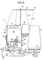
- Fig. 2 eine Seitenansicht,
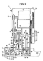
- Fig. 3 einen schematischen Teilschnitt der Seitenansicht,
- Fig. 4 bis 6 drei Arbeitspositionen des Nähmechanismus,
- Fig. 7 das schematische Stichbild, das den Fadenverlauf einer mit der Nähmaschine vorgenommenen Umkettelung zeigt,
- Fig. 8 eine schematische Teil-Frontansicht mit abgenommener Abdeckung, die die Schneideinrichtung und die Druckfußentlastung zeigt,
- Fig. 9 einen Antrieb der Transport-Zahnleiste,
- Fig. 10 einen schematischen Teilschnitt, etwa in der Ebene des Materialauflagetisches und
- Fig. 11 eine perspektivische Ansicht einer Fadenführungsöse.
- 1 is a front view of a sewing machine,
- 2 is a side view,
- 3 shows a schematic partial section of the side view,
- 4 to 6 three working positions of the sewing mechanism,
- 7 shows the schematic stitch pattern, which shows the course of the thread of a loop made with the sewing machine,
- 8 is a schematic partial front view with the cover removed, showing the cutting device and the pressure foot relief,
- 9 is a drive of the transport rack,
- Fig. 10 is a schematic partial section, approximately in the plane of the material support table and
- Fig. 11 is a perspective view of a thread guide eyelet.
Die in den Zeichnungen gezeigte Nähmaschine 11 hat ein unteres, relativ flaches Basisteil 12 und ein von diesem nach oben ragendes turm- oder säulenartiges Antriebsteil 13 (Fig. 1 und 2), das den Antriebsmotor 14 (Fig. 3) und die wesentlichen Antriebsmechanismen umfaßt. Am Basisteil befindet sich eine etwa unter dem Nähmechanismus 15 angeordnete Laufrolle 16, während sich zwei weitere, selbstlenkend ausgebildete Rollen 17 unter einem ausklappbaren und mittels eines Hebels 18 arretierbaren Tragteller 19 befinden, an dem sich Halterungen 20 für zwei Garnspulen 21 befinden und der eine Vorratsrolle 22 eines Beilaufbandes 23 aufnimmt. Eine Halterung 24 einer Zwirnspule 25 ist am abnehmbaren Gehäuse 26 des Antriebsteiles vorgesehen. Das Gehäuse 26 ist mit einem Handgriff 27 zum Transport versehen. Das von den entsprechenden Spulen 21, 25 kommende Garn 28 und Zwirn 29 läuft über später noch beschriebene Ösen 30 an einem ebenfalls abschwenkbaren oder abnehmbaren, zum Spannungsausgleich federnden Fadenabspulrahmen 31 und wird dann von oben über Ösen 32 je einem Fadenspanner 33 zugeführt, die ebenfalls am Gehäuse 26 angebracht sind.The
Die Fadenspanner 33 enthalten je eine Grundplatte 34, auf der um eine waagerechte Achse 35 eine Rolle 36 drehbar gelagert ist (Fig. 1). Ein aus Federstahlblech gebogener und um eine Achse 38 schwenkbarer Andruckteil 37 liegt an der Mantelfläche 39 flächig an, und zwar über einen Winkel von ca. 90° oder darüber. An dem der Achse gegenüberliegenden Ende des Andruckteils befindet sich eine Führungsöse 40 für den Faden 28 bzw. 29. Der Andruckteil 37 wird über eine Anstellschraube und eine darin geführte Feder so an die Rolle angedrückt, daß der Faden dazwischen flächig gepreßt wird. Da die Rolle 36 beim Durchziehens des Fadens mitdrehen kann, kann bei vergleichbarer Spann- bzw. Bremswirkung des Fadenspanners die Andruckkraft des Andruckteils 37 relativ hoch sein. Zusammen mit der flächigen Anlage können so durch Fadendrall vorher oder im Fadenspanner entstehende Überdrehungen des Fadens (Kinken) vermieden bzw. laufen durch. Eine in Fadenlaufrichtung vor dem Fadenspanner 33 aufgetretene Hemmung führt zu einer Druckverringerung des Andruckteils 37 durch einen aufwärts gerichteten Zug auf die Öse 40, so daß sich eine automatische Spannungskontrolle bzw. -regelung ergibt.The thread tensioners 33 each contain a
Der Zwirn 29 läuft nach einer Umschlingung der Rolle 36 um 130 bis 180° über eine Spannungs-Ausgleichsfeder 42 und eine Öse 43 einem Fadenheber 44 zu, der zusammen mit der Nadel oszillierend angetrieben ist und das Öhr 45 in der Nadel 46 von der Fadenabzieharbeit entlastet (Fig. 3).The
Ein gleicher Fadenspanner ist für das Garn 28 vorgesehen (Fig. 1), das nach der Rolle 36 direkt durch die Öse 43 einem Garnführungskanal 47 in Form eines gebogenen Rohres zuläuft, durch den es bis zum Nähmechanismus 15 läuft.An identical thread tensioner is provided for the yarn 28 (FIG. 1), which, after the
Der Antrieb der Nähmaschine 11 erfolgt von einer Hauptwelle 48 aus (Fig. 3), die über ein geeignetes Getriebe, hier ein zweistufiges Rundriemen-Untersetzungsgetriebe, vom Motor 14 angetrieben ist. Ein außerhalb des Gehäuses 26 angeordnetes Handrad 29 auf der Hauptwelle 48 ermöglicht eine Feineinstellung, z.B. zum Einfädeln. Auf der in einem Grundrahmen 50 gelagerten Hauptwelle 48 sind zwei Exzenter 51 zum Antrieb der Materialtransportmittel 52 angeordnet. An dem dem Handrad 49 entgegengesetzten Ende der Hauptwelle 48 ist ein Kurbeltrieb angebracht, der aus zwei scheibenartigen Kurbelwangen 53, 54, einem diese verbindenden Kurbelzapfen 55 und einem frei auskragenden Kurbelzapfen 56 besteht. Die innere Kurbelwange 53 ist als Antriebsnocken einer Schneideinrichtung mit zwei einander gegenüberliegenden Nockenerhebungen am Umfang ausgebildet (Fig. 8). Der Kurbelzapfen 56 betätigt über ein Pleuel 57 den Antrieb der in Längsrichtung gleitend geführten, gegenüber der Materiallaufrichtung 58 leicht rückwärts geneigt angeordneten Nadelstange 59. Das Pleuel 57 greift an dieser über einen auf der Nadelstange 59 festgeklemmten Klemmblock 60 an, der auch den Fadenheber 44 trägt, der durch einen Schlitz im Gehäuse 26 nach außen ragt. Der im Basisteil 12 angeordnete Schlaufenbildungsmechanismus 61, der anhand der Figuren 3 bis 6 beschrieben wird, wird von dem Kurbelzapfen 55 über das Pleuel 62 angetrieben. Es schwenkt über einen Antriebshebel 63 eine Welle 64 oszillierend hin und her, an der ein Garngreifer 65 und ein Betätigungshebel 68 drehfest angebracht sind.The
Der Garngreifer 65 hat eine Bogen- oder Ringsegmentform in seinem äußeren Abschnitt, der ein Garnöhr 69 nahe seinem vorderen Ende trägt und über einen radialen Arm mit der Welle 64 verbunden ist.The
Um eine Welle 70 ist ein Überwendlichgreifer 66 schwenkbar gelagert, der über eine Schubstange 71 vom Hebel 63 aus angetrieben wird. Er hat eine Kreisbogenform, an deren einem Ende die Welle 70 befestigt ist, während das andere Ende mit einer Greifergabel 150 versehen ist.An
Ein Haltegreifer 67 mit einem Haltefinger 151 an seinem vorderen Ende ist um eine Welle 72 schwenkbar und wird vom Hebel 68 über einen Hebelarm 73 angetrieben. Ein Anschlaghebel 74 wirkt mit einem Gehäuseanschlag 75, gegen den er unter der Kraft einer Feder 76 gedrückt wird, zur Begrenzung der Bewegung des Haltegreifers 67 zusammen.A holding
Die Transportmittel 52 für das zu umkettelnde Material 80 (Fig. 9) enthalten eine Transport-Zahnleiste 81, die eine in Fig. 9 strichpunktiert angedeutete ovale Bewegungsbahn 82 durchläuft, so daß jeweils auf einen Transporthub, bei dem die Zahnleiste über der Ebene des Materialauflagetisches 83 sich in Transportrichtung 58 bewegt, ein Rückhub in unter die Ebene 83 abgesenkter Position erfolgt. Bewirkt wird dies über die an die Exzenter 51 angeschlossenen Pleuel 84, 85. Das Pleuel 84 verschwenkt einen Hebel 86, indem es an einer Gewindebuchse 87 angelenkt ist, die auf einer mit einem sehr steilen Außengewinde versehenen Einstellgewindestange 88 mittels eines Einstellknopfes 89 verschiebbar ist. Der Hebel schwenkt um die Achse 90, während an seinem anderen Ende ein Hebel 91 angelenkt ist, der an seinem anderen Ende die Transportzahnleiste 81 trägt. In einigem Abstand von der Anlenkung 92 an den Hebel 86 greift das Pleuel 85 an.The transport means 52 for the material to be linked 80 (FIG. 9) contain a
Bei Drehung der Hauptwelle 48 wird durch das Pleuel 84 die Gewindestange 88 und der damit in Verbindung stehende Hebel 86, wie in Fig. 9 angedeutet, hin und her geschwenkt. Dadurch erhält der Hebel 91 und damit die Transportzahnleiste 81 eine im wesentlichen horizontal gerichtete Längsbewegung beigebracht, während über das Pleuel 85 diesem eine etwa vertikal gerichtete Bewegung überlagert wird, die gemeinsam die Bewegungsbahn 82 ergeben.When the
Fig. 8 zeigt eine Schneideinrichtung 93 und einen Druckfuß 94, der das Material schräg von oben gegen die Transport-Zahnleiste 81 drückt (s. auch Fig. 1). Dieser Druckfuß 94 ist parallel zur Nadelachse 95 verschiebbar geführt und wird mittels einer Feder 96 so nach unten gepreßt, daß sein bügelförmiger und die Nadel gabelartig umgreifender Fußteil 97 nach unten gegen das Material gedrückt wird. Mit einem Handhebel 98 kann der Druckfuß angehoben, und, wenn die im fol genden beschriebene automatische Schneideinrichtung eingeschaltet und wirksam ist, auch in der angehobenen Stellung arretiert werden.FIG. 8 shows a
Um die den Druckfuß führende Stange 99 greift eine Klemmplatte 100, die zusammen mit einem strichliert gezeichneten Hebel 101 um eine Achse 102 schwenkbar ist. Die Schwenkung erfolgt über eine am Hebel angebrachte Blattfeder 103, die von einem Elektromagneten 104 bei seinem Anziehen den Hebel 101 entgegen dem Uhrzeigersinn verschwenkt. Während der Druckfuß 94 an seinem oberen Ende in einer Schiebeführung seiner Stange 99 im Grundrahmen geführt ist, ist er unten mittels einer Schwinge 105 im wesentlichen vertikal beweglich geführt.Around the
Der Hebel 101 hat einen nach unten fortgesetzten Arm 106, dessen schräge Endfläche mit dem freien Ende eines hebelartigen Messerantriebsgliedes 78 in Eingriff kommen kann, das um eine Achse 107 am Grundrahmen schwenkbar angeordnet ist und an einem Messer 108 angelenkt ist. Das Messer befindet sich an einer im wesentlichen vertikal geführten Messerstange 109, an der eine Feder 110 angreift, die das Messer in seine obere Endlage zu ziehen sucht.The
Die doppelnockenartig ausgebildete Kurbelwange 53 kann mit dem Messerantriebsglied 78 zusammenarbeiten, um das Messer mit je zwei Hüben je Umdrehung der Hauptwelle 48 oszillierend anzutreiben.The double cam-
Das Messer hat eine entgegen der Materialtransportrichtung 58 sowie nach unten gerichtete schräge Schneide 111, an deren Ende sich eine Führungsnase 112 nach unten erstreckt. Es wirkt mit einem Gegenmesser 113 (Fig. 10) zusammen, wobei die Führungsnase das Messer auch in seiner oberen Position zu dem am Materialauflagetisch 83 angebrachten Gegenmesser 113 ausgerichtet hält.The knife has an
Aus Fig. 10 ist zu erkennen, daß das Gegenmesser 113 an einer in den Materialauflagetisch 83 eingesetzten, auswechselbaren Stichplatte 114 angeordnet ist und um einen kleinen Winkel schräg zur Materiallaufrichtung 58 angeordnet ist. Dies berücksichtigt die Schnittverhältnisse beim Eckenrunden, bei dem meist die Nadel 46 die Drehachse bestimmt.From Fig. 10 it can be seen that the
In Fig. 10 ist noch zu erkennen, daß im Bereich der Nadel 46 eine in Materiallaufrichtung 58 gerichtete Führungsnase 115 vorgesehen ist, die die Materialkante führt und um die herum sich das Garn 28 bei der Bildung einer Überwendlichschlaufe legt, bevor es beim Weitertransport davon abrutscht und festgezogen wird. Zwischen der Materialkante und der Führungsnase 115 wird das Beilaufband 23 zugeführt, falls es verwendet wird.In Fig. 10 it can still be seen that in the region of the needle 46 a
Im Materialauflagetisch ist in Materiallaufrichtung mit Abstand vor der Nadelposition und auch mit Abstand von einer wegschwenkbaren Führungsplatte 116 für die zu bekettelnde Materialkante ein Fotofühler 117 angeordnet, der Licht von einer Lampe 118 empfangen kann, die als Arbeitslicht im Nähbereich ausgebildet ist.A
Der Fotofühler 117 gehört zu einer Einschalteinrichtung, die ein Steuergerät im elektrischen Steuerungsteil 119 (Fig. 2) enthält und kann darüber den Elektromagneten 104 zur Betätigung der Schneideinrichtung und Druckfußanhebung steuern (Fig. 8). Über einen Schalter 120 kann die Schneidautomatik angewählt oder manuell ausgeschaltet werden.The
An dem abschwenkbaren Führungsblech 116 ist eine Einlaufrolle 121 angebracht, die vor dem Anfang des Materialauflagetisches 83 mit ihrer Oberkante etwas über deren Ebene liegt und deren Achse so schräg angeordnet ist, daß ein sich auf ihr bewegender Gegenstand unter einem kleinen Winkel gegen die Führungsplatte 160 geschoben wird, insbesondere, wenn eine ebenfalls wegschwenkbare Druckrolle 122 das dazwischen geführte Material federnd auf die Einlaufrolle 121 drückt. Die schräge Achse 123 der Einlaufrolle 121 setzt sich als drehbare Welle auf der Rückseite der Führungsplatte 116 fort und trägt dort einen Impulsgeber 124, der beispielsweise einen Permanentmagneten 124 enthalten kann (Fig. 10). Dieser arbeitet mit einem berührungslosen Impulsnehmer 125 am Basisteil zusammen und gibt somit je einen Zählimpuls für einen Materialvorschub, der dem Umfang der Einlaufrolle entspricht. Das Ergebnis dieser Längenzählung kann über eine Anzeige 126 (Fig. 2) abgelesen und beispielsweise als Basis für eine Kostenberechnung verwendet werden. Kugelführungen 127 erleichtern die Materialverschiebung auf dem Tisch 183.On the
Fig. 11 zeigt eine Fadenführungsöse 32 am Gehäuse 26. Die Ösen 30 am Fadenabspulrahmen 31 sind in ihrem Grundprinzip gleich ausgebildet. Die Öse 32 besteht aus einer Schlaufe aus einem blanken und glatten Draht 129, der auf einer Grundplatte 128 mit seinen beiden Enden angebracht ist. Die Öffnung 130 der Öse ist von einer Ringbegrenzung umgeben, die aus anderthalb spiraligen Drahtwindungen besteht, die eng aneinander liegen und somit ein Einklemmen des Fadens zwischen ihnen verhindern. An die Ringbegrenzung 131 schließen sich zwei Verbindungsschenkel 132 an, die die Ringbegrenzung 131 mit der Basisplatte 128 verbinden. Diese beiden Schenkel haben mit ihren Außenflächen einen Abstand voneinander, der mindestens so groß ist wie die größte Breite der Ringbegrenzung 131. Sie können parallel zueinander verlaufen oder evtl. etwas von der Ringbegrenzung zur Basisplatte hin divergieren.11 shows a
Die beschriebene Öse verhindert, daß ein loser Faden sich in einer Schlaufe um den Verbindungsabschnitt legt und sich dann durch Bekneifen der übereinander liegenden Garnabschnitte festzieht, was zum Fadenbruch führen könnte. Bei dieser Ösenausbildung rutscht der Faden stets von alleine wieder über die Ringbegrenzung hinweg, wenn Zug darauf kommt.The eyelet described prevents a loose thread from looping around the connecting section and then tightening by pinching the yarn sections lying one above the other, which could lead to thread breakage. With this eyelet formation, the thread automatically slips over the ring boundary again when it comes to pull.
Die Nähmaschine nach der Erfindung arbeitet nach folgendem Verfahren:The sewing machine according to the invention works according to the following method:
Nachdem die Nähmaschine beispielsweise an eine Baustelle transportiert, durch Abklappen des Tragtellers 19 in die in Fig. 2 gezeigte Position aufgestellt und so arretiert wurde, können Garn- und Zwirnspulen 21, 25 aufgebracht und die Fäden 28, 29 eingefädelt werden. Der Verlauf des Zwirns ist bereits beschrieben worden. Zum Einfädeln des Garns 28 wird durch einen Einfädelkanal 133, der dem Basisteil 12 in Ver längerung des Garnführungskanals 47 verläuft, ein Einfädelwerkzeug 158 in Form eines Drahtes mit einem Haken an seiner Vorderseite eingeführt. Da die Mündung des Einfädelkanals 133 mit der Mündung des Garnführungskanals 47 und dem Öhr 69 im Garngreifer 65 fluchtet, wenn die Maschine sich in einer am Handrad 49 markierten Position befindet, kann das Einfädelwerkzeug 158 soweit hindurchgesteckt werden, bis es aus der äußeren Öffnung 134 des Garnführungskanals 47 heraussieht. Das Garn, das aus mehreren Einzelgarnen bestehen kann, kann dann in den Haken eingehängt und in einem Zug durch den Garnführungskanal und das Öhr 69 und den Einfädelkanal 133 hindurchgezogen werden. Nachdem es aus dem Haken entfernt ist, ist die Maschine betriebsbereit.After the sewing machine has been transported to a construction site, for example, and has been set up by locking the support plate 19 into the position shown in FIG. 2 and thus locked, thread and
Das zu umkettelnde Material 80 wird dann, in Fig. 1 von links beginnend, auf den Materialauflagetisch 83 gebracht. Die Druckrolle 122 kann hochgeschwenkt sein, wenn es sich um ein größeres Materialstück handelt. Die Maschine kann stationär, z.B. auf einem Tisch, aufgestellt sein. Vorteilhaft wird sie aber, auf ihren Rollen 16 und 17 laufend, an dem ausgelegten Material entlanggefahren, das sich nur relativ wenig hochwölben muß, um auf den Materialauflagetisch 83 zu kommen, weil der Basisteil 12 aufgrund der beschriebenen Ausbildung des Nähmechanismus relativ flach ausgebildet sein kann. Dabei sorgen auch die Einlaufrolle 121 und die Kugelführungen 127 für einen leichten Lauf. Ein Handgriff 138 ist mittels einer Rastbefestigung 153 am Gehäuse 26 anbringbar und über eine elektrische Steckverbindung mit der Nähmaschine 11 zu verbinden. Er kann auch an einem in Fig. 1 strich liert angedeuteten Verlängerungsstiel 152 angebracht werden, der seinerseits an der Rastbefestigung 153 eingerastet werden kann. Das erleichtert das Führen der Maschine am Boden.The material 80 to be linked is then brought to the material support table 83, starting from the left in FIG. 1. The
Die zu umkettelnde Kante 135 des Materials 80 läuft an dem Führungsblech 116 entlang und wird unter den Fußbügel 97 des Druckfusses 94 geführt, der zu diesem Zweck mittels des Anhebehebels 98 in eine obere Position gestellt wurde. Der Druckfuß wird daraufhin abgesenkt und drückt die Unterseite des Materials auf die Transport-Zahnleiste 81.The
Nach Einschalten des Hauptschalters 136 (Fig. 2) wird dann die Maschine an dem zum Transport abnehmbaren Handgriff 138 ergriffen und mittels eines im Griff vorgesehenen Betriebsschalters 137 in Gang gesetzt. Der anhand von Fig. 9 beschriebene Transport wird dadurch in Gang gesetzt und transportiert das Material in Transportrichtung 58 bzw. zieht die Maschine in entsprechende Richtung an der Materialkante entlang. Die Transportlänge je Hub, d.h. die Stichlänge, kann über den Einstellknopf 89 eingestellt werden, der die Gewindebuchse 87, an der das Pleuel 84 angreift, auf der Gewindestange 88 verschiebt und damit den Schwenkwinkel des Hebels 86 und damit die Längsverschiebung der Stange 91 und der Zahnleiste 81 bestimmt.After the main switch 136 (FIG. 2) is switched on, the machine is then gripped by the
Die Nahtbildung wird anhand der Figuren 4 bis 6 beschrieben. In Fig. 4 hat der Überwendlichgreifer 66 mit seiner Greifergabel 150 eine Garn-Überwendlichschlaufe 139 um die Materialkante 135 herumgezogen und in eine Position jenseits der Nadel 46 gebracht, so daß diese in die Überwendlichschlaufe 139 einstechen kann. Dabei greift der Überwendlichgreifer 66 hinter der Nadel vorbei, die Nadel sticht in die Schlaufe, d.h. hinter dem vorderen Garn der Schlaufe ein, während der Zwirn außerhalb der Schlaufe bleibt, d.h. vor dem Garn vorbeiläuft. Dies bezieht sich auf die in den Figuren 4 bis 6 gewählte Darstellung, bei der die Transportrichtung des Materials (Pfeil 58) auf den Betrachter zu gewählt ist.Seam formation is described with reference to FIGS. 4 to 6. In FIG. 4, the overlocking
Aus Fig. 4 ist ferner zu erkennen, daß das aus dem Garnführungskanal 47 kommende Garn 28 durch das Öhr 69 des Garngreifers 65 läuft und durch Verschwenkung entgegen dem Uhrzeigersinn dieses nachzieht. In Fig. 5 hat der Überwendlichgreifer 66 die Überwendlichschlaufe 139 freigegeben, die Nadel das Material durchstochen und dadurch eine Zwirnschlaufe um einen Arm der Überwendlichschlaufe an der Oberseite gebildet.From Fig. 4 it can also be seen that the
Der nun wieder im Uhrzeigersinn schwenkende Garngreifer 65 fährt oberhalb des Nadelöhrs 45 zwischen der Nadel und dem Zwirn hindurch und zieht, wie insbesondere aus Fig. 6 zu sehen ist, das Garn zur Bildung der Überwendlichschlaufe durch eine untere Zwirnschlaufe. Eine in Fig. 6 angedeutete, an die Mündung des Garnführungskanals 47 anschließende Garnleitrolle 154 erleichtert das Nachziehen der Garnlänge. Die Überwendlichschlaufe 139 bildet sich also zwischen der Garnzuführung über dem Garnführungskanal 47 und einem Garnabschnitt, der an die letzte Überwendlichschlaufe anschließt. In diesem Bereich greift der Haltegreifer 67 ein und verhindert, daß dieser Garnabschnitt (Halteschlaufe 140) bei der Bildung der Überwendlichnaht zu weit in Richtung auf die Kante 135 gezogen wird. In dieser Position ist nämlich die untere Zwirnschlaufe 141 noch nicht festgezogen, und somit würde der Zwirn nicht im Bereich der Stichreihe, sondern irgendwo zwischen dieser und der Kante 35 liegen.The
Aus Fig. 6 ist zu erkennen, daß der Überwendlichgreifer 66 nach seinem völligen Zurückschwenken wieder aufwärtsläuft und dabei ist, in die Überwendlichschlaufe einzugreifen und diese um die Kante 135 herumzulegen, während der Garngreifer 65 wieder in die in Fig. 4 dargestellte Position zurückschwenkt und die Nadel aufwärtsläuft. Eine in Fig. 5 angedeutete Nadelführung 155 unterhalb der Stichplatte verhindert ein Verbiegen der Nadel beim Festziehen des Stichs.From Fig. 6 it can be seen that the
Mit diesem Nähmechanismus wird die in Fig. 7 gezeigte Zweifaden-Überwendlichnaht 156 hergestellt, die bei großer Haltbarkeit und geringem Verbrauch an dem relativ teuren Zwirn eine große Haltbarkeit gewährleistet. Es ist zu erkennen, daß je Stich 142 zwei Garnschlaufen um die Kante 135 herum gelegt werden, während der Zwirn 29 in Draufsicht fast geradlinig von Stich zu Stich verläuft und die Garnschlaufen festhält. Es kann also ein dekoratives, relativ bauschiges und trotzdem preisgünstiges Garn verwendet werden, da dies beim Nähvorgang nur schwach belastet wird und die Haltefunktion von dem Zwirn 29 übernommen werden kann. Es war bereits erwähnt worden, daß die Begriffe "Garn" und "Zwirn" hier nur zur Unterscheidung der beiden Fadenfunktionen und nicht notwendig ihrer Art benutzt werden. So kann als Zwirn beispielsweise jede ausreichend feste Fadenart verwendet werden, beispielsweise auch monofiler Kunststoff-Faden. Das gleiche gilt für den Begriff "Garn".With this sewing mechanism, the two-
Es sei noch erwähnt, daß die Überwendlichschlaufe 139 nicht direkt um die Kante 135 herumgezogen wird, sondern um die Führungsnase 115 (Fig. 10), von der sie aber vor dem Festziehen der Überwendlichschlaufe abrutscht. Zwischen Materialkante 135 und Führungsnase 15 läuft auch, wenn gewünscht, das Beilaufband 23 ein, das die Kante 135 abdeckt, um beispielsweise bei sehr langflorigem Teppich zu verhindern, daß Florteile zwischen den Garnschlaufen herausstehen. Wegen der ausgezeichneten Nahtbildungsqualitäten und dem großen Verstellbereich der Stichlängen kann auch mit einem dekorativem Beilaufband gearbeitet werden, das, beispielsweise mit monofil durchsichtigem Garn lediglich mit relativ großem Stichabstand festgekettelt wird.It should also be mentioned that the
Es sei noch erwähnt, daß die Fadenzuführung aufgrund der beschriebenen Anordnung sehr gleichförmig und ohne Gefahr einer Überspannung erfolgt. Der durch die Spulenabwicklung nach oben erzeugte Zusatzdrall in den Fäden wird durch die beschriebenen Fadenspanner ausgeglichen und dem Garn bzw. Zwirn wird auf der Zulaufseite kein zusätzlicher Drall aufgezwungen, was bei Platten-Fadenspannern infolge des schraubenförmigen Verlaufs der garnkardeele geschehen könnte. Die Spannungsausgleichsfeder 42 zusammen mit dem Fadenheber sorgt für einen gleichmäßigen Durchlauf des Garns durch den Fadenspanner. Die Zwirnspannung braucht allerdings bei der Nähmaschine nicht hoch gewählt zu werden, weil durch den Haltegreifer 67 die Zurückhaltung der unteren Garnschlaufe im Stichbereich nicht mittels hoher Zwirnspannung erreicht zu werden braucht. Die Gefahr eines Zwirnbruchs ist daher wesentlich verringert.It should also be mentioned that the thread feed is very uniform due to the arrangement described and without risk of overvoltage. The additional twist in the threads generated by the bobbin winding is compensated for by the thread tensioners described and no additional twist is imposed on the yarn or twine on the inlet side, which could happen with plate thread tensioners as a result of the helical course of the yarn cardels. The
Bei Annäherung an eine Materialecke wird der bisher vom Material 80 abgedeckte Fotofühler 117 frei und erhält Licht von der Lampe 118. Dadurch wird die Einschalteinrichtung ausgelöst, und der bis dahin stromlose Magnet 104 zieht an. Er schwenkt dabei die Blattfeder 103 entgegen dem Uhrzeigersinn, so daß auch der Hebel 101 in diese Richtung verschwenkt wird (Fig. 8). Dadurch wird die Klemmplatte 100 mit den Kanten ihres Loches an die Druckfußstange 99 angepreßt und verklemmt diese so, daß sie sich nur noch aufwärts, aber nicht mehr abwärts bewegen läßt. Da während des Transportes durch die Transportzahnleiste 81 das Material und damit auch der Druckfuß periodisch angehoben und abgesenkt wird, wird jetzt der Druckfuß nur noch aufwärts bewegt und bleibt dann in der oberen Lage stehen. Er hat dann in der oberen Transportposition noch Kontaktdruck, gibt aber beim Absenken der Zahnleiste 81 das Material frei, so daß es relativ zur Nähmaschine 11 gedreht werden kann (bzw. umgekehrt). Gleichzeitig schwenkt der untere Hebelarm 106 so nach rechts, daß der bisher daran anliegende Arm des Messerantriebsgliedes 78 frei wird und damit Messer 108 und Messerstange 109 unter der Kraft der Feder 110 gegen die Kurve 53 gedrückt und von dieser oszillierend bewegt werden können. Das Messer arbeitet also und schneidet mit seiner schrägen Schneide 111 im Zusammenwirken mit der Gegenschneide 113 eine z.B. bisher spitz rechtwinklige Ecke des Materials in einem nicht zu großen, aber gleichmäßigen Radius ab. Die dabei entstehenden Schnittabfälle können durch einen Abfallkanal 143 (Fig. 1 und 10) im Basisteil 12 abgeführt werden.When approaching a material corner, the
Der Schnittradius wird dadurch bestimmt, daß die Führungsplatte 116 mit ihrer in Transportrichtung 58 weisenden Kante 144 in einem Abstand vom Nähbereich, und insbesondere der Nadelposition liegt. Erst wenn die Materialecke diese Kante 144 passiert hat, kann das Material relativ zur Maschine gedreht werden. Die Rundung wird dann sofort anschließend umkettelt. Nachdem die Rundung beendet ist, überdeckt das Material wieder den Fotofühler 117, und die Einschalteinrichtung macht den Magneten 104 stromlos. Dadurch wird der Hebel 101 im Sinne einer Drehung im Uhrzeigersinn belastet, die Klemmplatte 100 gibt die Druckfußstange 99 frei, und das Messerbetätigungsglied 78 gleitet bei seiner Schwenkbewegung an dem Arm 106 entlang und greift kurz vor dem Totpunkt unter diesen Hebel und wird damit blockiert. Durch die aus Fig. 8 zu erkennende Schräge der unteren Fläche des Arms 106 arbeitet sich das Messerbetätigungsglied in eine Position, wo es von der Kurve 53 nicht mehr bewegt wird. Damit ist das Messer in seiner unteren Position blockiert, so daß auch die Schneide versenkt und abgedeckt liegt.The cutting radius is determined by the fact that the
Es ist möglich, einen zusätzlichen Fotofühler 157 (Fig. 10) in geringem Abstand vom normalen Verlauf der Kante 135 hinter der Stichposition vorzusehen, der mit dem Fotofühler 117 wirkungsmäßig in Reihe geschaltet ist. In diesem Fall würde das Messer erst dann anlaufen, wenn das Material zum Eckenrunden auf dem Tisch 83 gedreht wird und nicht, wenn das Material z.B. beim Streifenketteln zu Ende ist. Da das Messer jedoch außerhalb des Verlaufs der Kante 135 arbeitet, stört dies kaum.It is possible to provide an additional photo sensor 157 (FIG. 10) at a short distance from the normal course of the
Claims (13)
Applications Claiming Priority (2)
| Application Number | Priority Date | Filing Date | Title |
|---|---|---|---|
| DE3900209A DE3900209A1 (en) | 1989-01-05 | 1989-01-05 | SEWING MACHINE, IN PARTICULAR TO BORDER OR. HEMING OF MATERIALS |
| DE3900209 | 1989-01-05 |
Publications (3)
| Publication Number | Publication Date |
|---|---|
| EP0377218A2 true EP0377218A2 (en) | 1990-07-11 |
| EP0377218A3 EP0377218A3 (en) | 1990-10-03 |
| EP0377218B1 EP0377218B1 (en) | 1995-04-19 |
Family
ID=6371625
Family Applications (1)
| Application Number | Title | Priority Date | Filing Date |
|---|---|---|---|
| EP89124060A Expired - Lifetime EP0377218B1 (en) | 1989-01-05 | 1989-12-28 | Overedge seaming machine, especially for carpets |
Country Status (5)
| Country | Link |
|---|---|
| US (1) | US5020458A (en) |
| EP (1) | EP0377218B1 (en) |
| JP (1) | JPH02234789A (en) |
| AT (1) | ATE121470T1 (en) |
| DE (2) | DE3900209A1 (en) |
Cited By (2)
| Publication number | Priority date | Publication date | Assignee | Title |
|---|---|---|---|---|
| CN108642723A (en) * | 2018-06-22 | 2018-10-12 | 苏州澳拓美盛自动化设备有限公司 | Carpet bound edge sewing work station |
| CN110945174A (en) * | 2017-08-22 | 2020-03-31 | 株式会社铃木制作所 | Thread supply device for a sewing machine for decorative stitching |
Families Citing this family (4)
| Publication number | Priority date | Publication date | Assignee | Title |
|---|---|---|---|---|
| US5209171A (en) * | 1992-04-21 | 1993-05-11 | Anderson Martin L | Carpet edge binding machine |
| JP3472325B2 (en) * | 1992-11-04 | 2003-12-02 | アジレント・テクノロジーズ・インク | Sample injection device |
| US5915614A (en) * | 1992-12-11 | 1999-06-29 | Avery Dennison Corporation | Self-contained button attachment assembly |
| US6055918A (en) * | 1998-06-30 | 2000-05-02 | N.C. Carpet Binding & Equipment Corporation | Portable carpet binder |
Citations (6)
| Publication number | Priority date | Publication date | Assignee | Title |
|---|---|---|---|---|
| US1915235A (en) * | 1927-04-07 | 1933-06-20 | Magee Carpet Co | Binding for the unselvaged edges of fabrics |
| US1961979A (en) * | 1931-06-22 | 1934-06-05 | Union Special Maschinenfab | Method of and machine for edging pile fabrics |
| FR771964A (en) * | 1934-04-18 | 1934-10-20 | Overlock machine on mobile cart | |
| US2238796A (en) * | 1939-06-10 | 1941-04-15 | Singer Mfg Co | Overedge sewing machine |
| US3943864A (en) * | 1974-12-16 | 1976-03-16 | J. M. Feighery Company | Carpet sewing machine |
| DE2500461A1 (en) * | 1975-01-08 | 1976-07-15 | Max Janser Fa | Carpet edge binding unit - is manually moved along edge for seaming with motor to operated fabric advance roller |
Family Cites Families (11)
| Publication number | Priority date | Publication date | Assignee | Title |
|---|---|---|---|---|
| US600502A (en) * | 1898-03-15 | Carpet-binding apparatus for sewing-machines | ||
| US1587957A (en) * | 1920-04-09 | 1926-06-08 | Huber Gustav | Machine for sewing together and covering the edges of knitted or woven fabrics |
| US2023316A (en) * | 1929-07-13 | 1935-12-03 | Ebert Fritz | Sack sewing machine |
| BE395326A (en) * | 1932-04-20 | |||
| US2575327A (en) * | 1948-01-23 | 1951-11-20 | United Shoe Machinery Corp | Carpet sewing machine |
| US2547821A (en) * | 1950-02-25 | 1951-04-03 | Thomas M Hartwell | Rug binding apparatus and method |
| US2691951A (en) * | 1952-09-26 | 1954-10-19 | Gellman Mfg Co | Thread guide for sewing machines |
| US2767671A (en) * | 1954-12-15 | 1956-10-23 | Shapiro Samuel | Automatic needle threader for sewing machines |
| US3079879A (en) * | 1959-11-30 | 1963-03-05 | Man Sew Corp | Overedge sewing machines |
| US3457884A (en) * | 1967-02-09 | 1969-07-29 | Lewis J Weaver | Carpet sewing mechanism |
| CH602960A5 (en) * | 1975-01-08 | 1978-08-15 | Janser Maximilian Fa |
-
1989
- 1989-01-05 DE DE3900209A patent/DE3900209A1/en not_active Withdrawn
- 1989-12-28 AT AT89124060T patent/ATE121470T1/en not_active IP Right Cessation
- 1989-12-28 DE DE58909189T patent/DE58909189D1/en not_active Expired - Fee Related
- 1989-12-28 EP EP89124060A patent/EP0377218B1/en not_active Expired - Lifetime
-
1990
- 1990-01-05 JP JP2000155A patent/JPH02234789A/en active Pending
- 1990-01-05 US US07/461,500 patent/US5020458A/en not_active Expired - Fee Related
Patent Citations (6)
| Publication number | Priority date | Publication date | Assignee | Title |
|---|---|---|---|---|
| US1915235A (en) * | 1927-04-07 | 1933-06-20 | Magee Carpet Co | Binding for the unselvaged edges of fabrics |
| US1961979A (en) * | 1931-06-22 | 1934-06-05 | Union Special Maschinenfab | Method of and machine for edging pile fabrics |
| FR771964A (en) * | 1934-04-18 | 1934-10-20 | Overlock machine on mobile cart | |
| US2238796A (en) * | 1939-06-10 | 1941-04-15 | Singer Mfg Co | Overedge sewing machine |
| US3943864A (en) * | 1974-12-16 | 1976-03-16 | J. M. Feighery Company | Carpet sewing machine |
| DE2500461A1 (en) * | 1975-01-08 | 1976-07-15 | Max Janser Fa | Carpet edge binding unit - is manually moved along edge for seaming with motor to operated fabric advance roller |
Cited By (4)
| Publication number | Priority date | Publication date | Assignee | Title |
|---|---|---|---|---|
| CN110945174A (en) * | 2017-08-22 | 2020-03-31 | 株式会社铃木制作所 | Thread supply device for a sewing machine for decorative stitching |
| CN110945174B (en) * | 2017-08-22 | 2021-11-09 | 株式会社铃木制作所 | Thread supply device for a sewing machine for decorative stitching |
| CN108642723A (en) * | 2018-06-22 | 2018-10-12 | 苏州澳拓美盛自动化设备有限公司 | Carpet bound edge sewing work station |
| CN108642723B (en) * | 2018-06-22 | 2023-09-15 | 苏州澳拓美盛自动化设备有限公司 | Carpet edge-covering sewing workstation |
Also Published As
| Publication number | Publication date |
|---|---|
| JPH02234789A (en) | 1990-09-17 |
| EP0377218B1 (en) | 1995-04-19 |
| US5020458A (en) | 1991-06-04 |
| ATE121470T1 (en) | 1995-05-15 |
| DE3900209A1 (en) | 1990-07-12 |
| DE58909189D1 (en) | 1995-05-24 |
| EP0377218A3 (en) | 1990-10-03 |
Similar Documents
| Publication | Publication Date | Title |
|---|---|---|
| EP0517045A1 (en) | Yarn working machine, particularly embroidering machine with yarn changing apparatus | |
| DE3124795C1 (en) | Thread cutting device for zigzag sewing machines | |
| DE2313717A1 (en) | DEVICE FOR THE PRODUCTION OF PASPLE OPENINGS IN CUT-OUT PARTS OF CLOTHING | |
| DE1941681A1 (en) | Thread cutting device on lockstitch sewing machines | |
| DE3116931A1 (en) | DEVICE FOR TAKING OUT AND CUTTING THE THREADS ON A SEWING MACHINE | |
| EP0377218B1 (en) | Overedge seaming machine, especially for carpets | |
| DE2025397A1 (en) | sewing machine | |
| DE3604299A1 (en) | METHOD FOR PULLING THE FREE THREADING END OF A NEEDLE THREAD FROM THE TOP OF A SEWING MATERIAL ON ITS BASE AND DEVICE FOR IMPLEMENTING THE METHOD | |
| DE2442264C3 (en) | Cutting device for a sewing machine | |
| DE3640486C2 (en) | ||
| DE1114690B (en) | Regular chain stitch sewing machine | |
| DE60005739T2 (en) | Device for avoiding seam loosening | |
| DE10125108B4 (en) | Multi-needle chain stitch sewing machine and method for forming a sewing pattern in a fabric | |
| DE2123601B2 (en) | Thread control device for a sewing machine | |
| DE2157100C3 (en) | Machine for sewing net webs together | |
| DE2650352C2 (en) | Sewing machine with a hook arranged above the stitch formation point | |
| DE10052167A1 (en) | Double chain stitch sewing machine includes bridging section in sewing plate separating recesses for sliding teeth advancing material and needle descent region, which also includes spring-loaded auxiliary foot | |
| CH693383A5 (en) | Device for cutting a suture in a sewing machine and use of the device to pull the upper thread down. | |
| DE4446138C1 (en) | Sewing unit with a sewing material holder that can be moved relative to the thread-guiding needle and a sewing material downholder with a needle passage opening | |
| DE603983C (en) | Single thread sewing machine with an eye needle penetrating the fabric from below | |
| DE2141669A1 (en) | Method for controlling the needle thread in sewing machines and sewing machines for its implementation | |
| DE2500461C3 (en) | Sewing machine for edging the edges of floor coverings or the like | |
| DE172388C (en) | ||
| DE515724C (en) | Sewing machine for joining two pieces of fabric with a relatively flat edge seam | |
| DE1660879C3 (en) | Device for sewing chain stitches for sewing machines |
Legal Events
| Date | Code | Title | Description |
|---|---|---|---|
| PUAI | Public reference made under article 153(3) epc to a published international application that has entered the european phase |
Free format text: ORIGINAL CODE: 0009012 |
|
| AK | Designated contracting states |
Kind code of ref document: A2 Designated state(s): AT BE CH DE FR GB IT LI LU NL SE |
|
| PUAL | Search report despatched |
Free format text: ORIGINAL CODE: 0009013 |
|
| AK | Designated contracting states |
Kind code of ref document: A3 Designated state(s): AT BE CH DE FR GB IT LI LU NL SE |
|
| 17P | Request for examination filed |
Effective date: 19901120 |
|
| 17Q | First examination report despatched |
Effective date: 19920703 |
|
| GRAA | (expected) grant |
Free format text: ORIGINAL CODE: 0009210 |
|
| AK | Designated contracting states |
Kind code of ref document: B1 Designated state(s): AT BE CH DE FR GB IT LI LU NL SE |
|
| PG25 | Lapsed in a contracting state [announced via postgrant information from national office to epo] |
Ref country code: NL Free format text: LAPSE BECAUSE OF NON-PAYMENT OF DUE FEES Effective date: 19950419 Ref country code: GB Effective date: 19950419 Ref country code: IT Free format text: LAPSE BECAUSE OF FAILURE TO SUBMIT A TRANSLATION OF THE DESCRIPTION OR TO PAY THE FEE WITHIN THE PRE;WARNING: LAPSES OF ITALIAN PATENTS WITH EFFECTIVE DATE BEFORE 2007 MAY HAVE OCCURRED AT ANY TIME BEFORE 2007. THE CORRECT EFFECTIVE DATE MAY BE DIFFERENT FROM THE ONE RECORDED.SCRIBED TIME-LIMIT Effective date: 19950419 Ref country code: FR Effective date: 19950419 Ref country code: BE Effective date: 19950419 |
|
| REF | Corresponds to: |
Ref document number: 121470 Country of ref document: AT Date of ref document: 19950515 Kind code of ref document: T |
|
| REF | Corresponds to: |
Ref document number: 58909189 Country of ref document: DE Date of ref document: 19950524 |
|
| PG25 | Lapsed in a contracting state [announced via postgrant information from national office to epo] |
Ref country code: SE Effective date: 19950719 |
|
| EN | Fr: translation not filed | ||
| NLV1 | Nl: lapsed or annulled due to failure to fulfill the requirements of art. 29p and 29m of the patents act | ||
| GBV | Gb: ep patent (uk) treated as always having been void in accordance with gb section 77(7)/1977 [no translation filed] |
Effective date: 19950419 |
|
| PG25 | Lapsed in a contracting state [announced via postgrant information from national office to epo] |
Ref country code: LU Free format text: LAPSE BECAUSE OF NON-PAYMENT OF DUE FEES Effective date: 19951231 |
|
| PGFP | Annual fee paid to national office [announced via postgrant information from national office to epo] |
Ref country code: AT Payment date: 19960123 Year of fee payment: 7 |
|
| PGFP | Annual fee paid to national office [announced via postgrant information from national office to epo] |
Ref country code: CH Payment date: 19960124 Year of fee payment: 7 |
|
| PGFP | Annual fee paid to national office [announced via postgrant information from national office to epo] |
Ref country code: DE Payment date: 19960221 Year of fee payment: 7 |
|
| PLBE | No opposition filed within time limit |
Free format text: ORIGINAL CODE: 0009261 |
|
| STAA | Information on the status of an ep patent application or granted ep patent |
Free format text: STATUS: NO OPPOSITION FILED WITHIN TIME LIMIT |
|
| 26N | No opposition filed | ||
| PG25 | Lapsed in a contracting state [announced via postgrant information from national office to epo] |
Ref country code: AT Effective date: 19961228 |
|
| PG25 | Lapsed in a contracting state [announced via postgrant information from national office to epo] |
Ref country code: CH Effective date: 19961231 Ref country code: LI Effective date: 19961231 |
|
| REG | Reference to a national code |
Ref country code: CH Ref legal event code: PL |
|
| PG25 | Lapsed in a contracting state [announced via postgrant information from national office to epo] |
Ref country code: DE Effective date: 19970902 |