EP0376570B1 - Cassette de mémorisation de données avec assemblage de protection d'écriture - Google Patents
Cassette de mémorisation de données avec assemblage de protection d'écriture Download PDFInfo
- Publication number
- EP0376570B1 EP0376570B1 EP89313212A EP89313212A EP0376570B1 EP 0376570 B1 EP0376570 B1 EP 0376570B1 EP 89313212 A EP89313212 A EP 89313212A EP 89313212 A EP89313212 A EP 89313212A EP 0376570 B1 EP0376570 B1 EP 0376570B1
- Authority
- EP
- European Patent Office
- Prior art keywords
- write
- protect
- detection
- container
- mating
- Prior art date
- Legal status (The legal status is an assumption and is not a legal conclusion. Google has not performed a legal analysis and makes no representation as to the accuracy of the status listed.)
- Expired - Lifetime
Links
- 238000013500 data storage Methods 0.000 title claims description 11
- 238000001514 detection method Methods 0.000 claims description 120
- 230000013011 mating Effects 0.000 claims description 53
- 230000014759 maintenance of location Effects 0.000 claims description 8
- 238000003780 insertion Methods 0.000 claims description 2
- 230000037431 insertion Effects 0.000 claims description 2
- 230000003287 optical effect Effects 0.000 description 15
- 238000005452 bending Methods 0.000 description 1
- 239000002184 metal Substances 0.000 description 1
- 230000004048 modification Effects 0.000 description 1
- 238000012986 modification Methods 0.000 description 1
- 238000000465 moulding Methods 0.000 description 1
- 229910001220 stainless steel Inorganic materials 0.000 description 1
- 239000010935 stainless steel Substances 0.000 description 1
- 229920003002 synthetic resin Polymers 0.000 description 1
- 239000000057 synthetic resin Substances 0.000 description 1
Images


Classifications
-
- G—PHYSICS
- G11—INFORMATION STORAGE
- G11B—INFORMATION STORAGE BASED ON RELATIVE MOVEMENT BETWEEN RECORD CARRIER AND TRANSDUCER
- G11B23/00—Record carriers not specific to the method of recording or reproducing; Accessories, e.g. containers, specially adapted for co-operation with the recording or reproducing apparatus ; Intermediate mediums; Apparatus or processes specially adapted for their manufacture
- G11B23/28—Indicating or preventing prior or unauthorised use, e.g. cassettes with sealing or locking means, write-protect devices for discs
- G11B23/288—Protecting disks from being written or overwritten
-
- G—PHYSICS
- G11—INFORMATION STORAGE
- G11B—INFORMATION STORAGE BASED ON RELATIVE MOVEMENT BETWEEN RECORD CARRIER AND TRANSDUCER
- G11B23/00—Record carriers not specific to the method of recording or reproducing; Accessories, e.g. containers, specially adapted for co-operation with the recording or reproducing apparatus ; Intermediate mediums; Apparatus or processes specially adapted for their manufacture
- G11B23/02—Containers; Storing means both adapted to cooperate with the recording or reproducing means
- G11B23/03—Containers for flat record carriers
- G11B23/0301—Details
- G11B23/0302—Auxiliary features
- G11B23/0303—Write protect features with a sliding part
Definitions
- This invention relates to a data storage case having a write/protect assembly, such as a disk cartridge, which means a recording medium, such as a disk-shaped recording medium, including an optical disk, a magneto-optical disk or a magnetic disk, accommodated in a container, such as a cartridge.
- a write/protect assembly such as a disk cartridge
- a recording medium such as a disk-shaped recording medium, including an optical disk, a magneto-optical disk or a magnetic disk, accommodated in a container, such as a cartridge.
- a disk cartridge which is comprised of a disk, such as an optical disk or a magneto-optical disk, which is accommodated within a cartridge, and on which are recorded information signals, such as data signals or video signals.
- This type of the disk cartridge such as is shown in US-A-4,460,930, is provided with a write/protect member which/protects from inadvertent errasure of the previously recorded information signals, which is caused by a mistaken recording operation on the disk.
- This write/protect member is movably provided within the cartridge. By moving the write/protect member, the mating detection elements provided at the write/protect member so as to be detected by the write/protect detection assembly provided on the recording and/or reproducing apparatus mounting the disk cartridge may be selectively moved between the first and the second positions within the detection hole in the cartridge.
- the write/protect detection assembly on the recording and/or reproducing apparatus detecting that the mating detection elements of the write/protect member are in the first or the second position results in the selection of whether the recording operation may or may not be made by the recording and/or reproducing apparatus.
- EP-A-0,185,364 taken into account with the preamble of claim 1 describes a disc cartridge which uses a write protect member which is visible from above or below but which is only accessible from below. During assembly this member is fitted laterally onto a protrusion formed on the lower part of the cartridge but the lateral view and access is blocked off by the fitting of the upper part.
- the conventional write/protect assembly provided on the disk cartridge accommodating an optical or a magneto-optical disk on which information signals can be recorded is so designed and constructed that the mating detection elements of the write/protect member face that flat side or surface of the main body of the cartridge which is confronted by the signal recording surface of the disk and into which is intruded the disk driving apparatus of the recording and/or reproducing apparatus.
- the recording and/or reproducing apparatus mounting a disk cartridge provided with a write/protect assembly, in which the mating detection elements of the write/protect member are exposed on the flat side only of the main body of the cartride, constraints are imposed on the mounting position of the write/protect detection assembly.
- the write/protect detection assembly need be provided in the vicinity of the disk driving apparatus.
- an optical pickup apparatus is provided on the side of the recording and/or reproducing apparatus on which the disk driving apparatus is mounted.
- the write/protect detection assembly is provided on the side of the disk driving apparatus.
- the protect of the recording cannot be detected unless the disk cartridge is attached at a predetermined position to the recording and/or reproducing apparatus.
- the present invention provides a data storage case having a write/protect assembly comprising;
- said write/protect member includes a plurality of the mating detection elements said mating detection elements being movable between first and second positions within said detection holes.
- the write/protect member is provided so that its mating detection elements are exposed to the detection holes formed in one lateral surface and at least one major surface of a container accommodating a recording medium, detection of write/protect may be made at least from the lateral surfaces and one major surface of the container.
- the present invention will be explained with reference to an embodiment in which the present invention is applied to a disk cartridge comprised of an optical disk for recording information signals and a cartridge accommodating the optical disk.
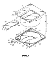
- the disk cartridge according to the present invention is comprised of a main body of the cartridge 1 formed by an upper half 2 and a lower half 3, each in the form of a rectangular flat plate formed by molding synthetic resin, abutted and secured to each other, and an optical disk 4 adapted to record information signals, such as data signals, and rotatably accommodated within the main body of the cartridge 1.
- the upper and the lower halves are rectangular in profile to form the main body of the cartridge 1 together.
- To the main body 1 is connected an opening/closing plate 3a so as to be rotated rearwards for opening and/or closing a disk inser- tion/removal opening formed in the side wall of the main body 1.
- This shutter 9 is, formed by bending a metal plate, such as a stainless steel plate, so as to be U-shaped in cross-section, and is comprised of a first closure surface section 9a for closing the aperture 7 in the upper half 2, a second closure surface section 9b for closing the aperture 8 in the lower half 3 and a connecting section 9c interconnecting the first and the second closure surface sections 9a, 9b. As shown in figs.
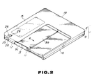
- this shutter 9 is fitted from the front side over the outer surfaces of the main body 1, so that the first and second surface sections 9a, 9b will overline the apertures 7, 8 formed in the flat sides of the upper and the lower halves 2 and 3, and is mounted to slide along the flat sides of the main body 1.
- This shutter 9 is slidingly biased by a torsion spring 10 provided at one corner on the front side of the main body 1 in a direction of closing the apertures 7 and 8.
- an operating pin, not shown, provided on the apparatus for engaging in an engaging opening 11 formed at one end of the connecting section 9c is actuated in the direction shown by an arrow A in Fig. 2.
- the shutter 9 is moved over an extent between the position of closing the apertures 7, 8 and the position towards the lateral side of the main body 1 of opening the apertures 7, 8.
- arcuate ribs 12 from the rear-side corners towards the front side, as shown in Fig. 1, for defining a substantially circular recesses 13 having the inside diameter slightly larger than the outside of the optical disk 4.
- These recesses 13 face each other by the arcuate ribs 12 abutting to each other form a disk housing section 14 surrounded by circumambient walls.
- the portion of the front wall 17 through which the shutter 9 is moved is to be opened to permit the movement of the torsion spring 10 urging the shutter 9.
- first, second and third detection holes 28, 29, 30 into which are fitted first, second and third mating detection elements 25, 26, 27 of a write/protect member 23.
- the first detection hole 28 is formed at a portion of the front wall 17 of the main body of the cartridge 1 which is not covered by the shutter 9.
- grooves 28a, 28b in the upstanding walls 21, 21 of the upper and lower halves 2 and 3 making up the front wall 17.
- the second detection hole 29 is formed in the upper half 2 forming the upper surface of the main body 1 orthogonal to the front wall 17, whereas the third detection hole 30 is formed in the lower half 3 forming the lower surface of the main body 1 in register with the second detection hole 29.
- the first to third detection holes 28, 29, 30 are formed in the three different sides of the main body of the cartridge 1.
- the first to third detection holes 28, 29, 30 are of such a size as will permit the first to third mating detection elements 25 to 27 to be moved between first and second positions.
- the write/protect member 23 is formed integally by the first to third mating detection elements 25 to 27.
- These first to third mating detection elements 25 to 27 are designed to be received in the first to third detection holes 28 to 30 when the write/protect member 23 is mounted in position within the main body of the cartridge 1.
- the first mating detection element 25 is projected at right angles from the vertically continuous second and third mating detection elements 26, 27.
- a resiliently deflectible slide guide 33 On the proximal side of the write/protect member 23 opposite to the projecting first mating detection member 25, there is provided a resiliently deflectible slide guide 33 having retention end ribs 31, 32.
- the above described write/protect member 23 is fitted into an engaging recess 34 formed in the lower half 3 so that the first to third mating detection elements 25, 26, 27 fit into the first to third detection holes 28, 29, 30, respectively, as shown in Fig. 5.
- the engaging recess 34 is of such a size as to movably support the write/protect member 23 to permit the first to third mating detection elements 25 to 27 to be moved between the first and the second positions within the first to third detection holes 28 to 30.
- the write/protect member 23 is attached within the engaging recess 34 in the lower half 3, with the third mating detection member 27 engaging in the third detection hole 30 and with the slide guide 33 pressed against a rear side wall 35 of the engaging recess 34.
- the write/protect member 23 is caused to be slid for selectively engaging the retention ribs 31, 32 with one or the other sides of the mating retention ribs 36a, 36b for selectively holding the first to third mating detection elements 25 to 27 at the first or the second position within the first to third detection holes 28 to 30.
- the write/protect member 23 is moved by manually thrusting any one of the first to third mating detection elements 25 to 27 for selectively shifting the first to third mating detection elements 25 to 27 to the first position towards one sides of the first to third detection holes 28 to 30 or to the second position towards the other sides of the detection holes 28 to 30.
- the variable positions of the first to third mating detection elements 25 to 27 within the first to third detection holes 28 to 30 whether the disk cartridge is in the recording enable state or in the recording inhibit state.
- positioning holes 38, 39 into which are engaged positioning pins, not shown, for positioning the disk cartridge when the disk cartridge is mounted in position in a disk mounting section within the recording/reproducing apparatus, as shown in Fig. 3.
- the write/protect member 23 is provided in the vicinity of one 38 of the positioning holes 38, 39.
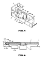
- the disk cartridge may be positioned accurately by a detection device 100 including a detection switch 101 provided on the recording/reproducing apparatus when the disk cartridge is attached to the recording/reproducing apparatus.
- the detection device 100 provided on the re- cording/repro ducing apparatus includes the detection switch 101 having an operating portion 102 and is so designed that actuation or non-actuation of the operating portion is an indication of whether the disk cartridge 110 is or is not in the recording enable state, as shown in Fig. 6.
- the first detection element 25 is disposed at the front wall 17 of the main body 1 and on the two major surface of the main body of the cartridge 1 orthogonal to the front wall 17, the detection switch 101 of the detection device 100 may be provided on the side of the recording and/or reproducing apparatus which is free of the disk driving device 103 for rotationally driving the disk 4 in the main body 1 or the optical pickup 104 for recording and/or reproducing information signals.
- the detection switch 101 may be arranged at a position facing the front wall 17 of the main body 1.
- a write/protect inhibit member 123 is provided with a rotary arm 51 on the proximal side of the first to third mating detection elements 25 to 27 and rotatably mounted by having the proximal end of the arm 51 pivotally mounted by a pivot pin 52 implanted on the lower half 3.
- the rotary write/protect member 123 is rotated on thrusting the first to third mating detecting elements 25 to 27 for changing the position of the first to third mating detection elements 25 to 27 within the first to third detection holes 28 to 30 for indicating whether the disk cartridge is in the record enable or record inhibit state.
- a movement control boss 53 is provided within at least one of the first to third detection holes 28 to 30, as shown in Fig. 7, for maintaining or defining the first and second positions of the first to third mating detection elements 25 to 27 within the first to third detection holes.
- the mating detection elements 25 to 27, when moved, are caused to ride over the control boss 53.
- the first to third mating detection elements 25 to 27 of the write/protect member 23 are disposed on the three different sides of the main body of the cartridge 1, so that the write/protect member 23 may be mounted without regard to the mounting position of the detection device provided on the recording/reproducing apparatus.
- the write/protect member 23 is provided on the front side of the main body of the cartridge 1. However, it may also be provided at the rear side corner opposite to the front side fitted with the shutter 9. In such case, the write/protect 23 member may be mounted without regard to the mounting position of the detection device provided on the recording/reproducing apparatus.
- the mating detection elements 25 to 27 may be mounted for facing one of the front wall 17, side walls 15, 16 or the rear wall 18 and to one major surface of the main body of the cartridge 1, so that the detection device may be positioned at least on the side not provided with the disk rotation and driving apparatus to simplify the structure of the disk rotation and driving apparatus.
- the present invention may also be applied to a cartridge accommodating a tape- shaped recording medium, such as magnetic tape, with the operation and result comparable with that of the above described embodiment.
- the feasibility of the data signal recording operation on the recording medium such as an optical disk, enclosed in an enclosure, such as a cartridge may be detected from one lateral surface and a major surface of the container normal to the lateral surface so that constraints of the mounting position of the write/protect detection assembly provided on the recording/reproducing apparatus are eliminated to facilitate the designing of the recording/reproducing apparatus.
- promt detection of the mistaken write/protect may be made in association with the attachment of the disk cartridge or the like enclosure for the recording medium to the recording/reproducing apparatus.
Claims (8)
caractérisée en ce que
sont prévus une pluralité de trous de détection (28, 29, 30) dont l'un au moins est formé dans une surface latérale (17) et l'un au moins est formé dans au moins une surface principale dudit boîtier (1), et en ce que ledit organe de protection d'écriture (23) comprend une pluralité d'éléments de détection appariés (25, 26, 27), lesdits éléments de détection (25, 26, 27) pouvant être déplacés entre des premières et des secondes positions à l'intérieur desdits trous de détection (28, 29, 30).
Applications Claiming Priority (2)
| Application Number | Priority Date | Filing Date | Title |
|---|---|---|---|
| JP170820/88U | 1988-12-29 | ||
| JP1988170820U JPH0292887U (fr) | 1988-12-29 | 1988-12-29 |
Publications (4)
| Publication Number | Publication Date |
|---|---|
| EP0376570A2 EP0376570A2 (fr) | 1990-07-04 |
| EP0376570A3 EP0376570A3 (en) | 1990-10-31 |
| EP0376570B1 true EP0376570B1 (fr) | 1994-03-09 |
| EP0376570B2 EP0376570B2 (fr) | 1998-03-25 |
Family
ID=15911938
Family Applications (1)
| Application Number | Title | Priority Date | Filing Date |
|---|---|---|---|
| EP89313212A Expired - Lifetime EP0376570B2 (fr) | 1988-12-29 | 1989-12-18 | Cassette de mémorisation de données avec assemblage de protection d'écriture |
Country Status (7)
| Country | Link |
|---|---|
| US (1) | US5041923A (fr) |
| EP (1) | EP0376570B2 (fr) |
| JP (1) | JPH0292887U (fr) |
| KR (1) | KR0151388B1 (fr) |
| CA (1) | CA2005944C (fr) |
| DE (1) | DE68913702T3 (fr) |
| MY (1) | MY105165A (fr) |
Families Citing this family (32)
| Publication number | Priority date | Publication date | Assignee | Title |
|---|---|---|---|---|
| JP2541242B2 (ja) * | 1987-10-30 | 1996-10-09 | ソニー株式会社 | ディスクカ―トリッジ |
| USD403671S (en) * | 1991-09-10 | 1999-01-05 | Sony Corporation | Optical disc cartridge |
| USD403672S (en) * | 1991-09-12 | 1999-01-05 | Sony Corporation | Optical disc cartridge |
| AU658916B2 (en) * | 1991-09-17 | 1995-05-04 | Sony Corporation | Disc cartridge having mistaken recording inhibiting mechanism |
| US5815344A (en) * | 1992-02-17 | 1998-09-29 | Sony Corporation | Disc cartridge loading apparatus |
| USD420653S (en) * | 1992-03-04 | 2000-02-15 | Sony Corporation | Optical disc cartridge |
| USD387743S (en) * | 1992-03-05 | 1997-12-16 | Sony Corporation | Optical disc cartridge |
| JP3353378B2 (ja) * | 1993-02-24 | 2002-12-03 | ソニー株式会社 | ディスクカートリッジ |
| TW230252B (en) * | 1993-03-17 | 1994-09-11 | Sony Co Ltd | A cassette having a recording medium and a recording/reproducing apparatus for use with the cassette |
| US5572817A (en) * | 1994-09-15 | 1996-11-12 | Chien; Tseng L. | Multi-color electro-luminescent light strip and method of making same |
| JPH0896552A (ja) * | 1994-09-27 | 1996-04-12 | Sony Corp | ディスクカートリッジ |
| US5903538A (en) | 1994-12-14 | 1999-05-11 | Matsushita Electric Industrial Co., Ltd. | Automatic disk change apparatus and disk tray for the apparatus |
| US5581540A (en) * | 1995-02-08 | 1996-12-03 | International Business Machines Corporation | Single disk write protection system for multiple-disk cartridge |
| US6724554B1 (en) | 1995-03-10 | 2004-04-20 | Iomega Corporation | Read/write protect scheme for a disk cartridge and drive |
| US5644444A (en) * | 1995-03-10 | 1997-07-01 | Iomega Corporation | Read/write protect scheme for a disk cartridge and drive |
| JPH0991915A (ja) * | 1995-09-21 | 1997-04-04 | Hitachi Maxell Ltd | ディスクカートリッジ |
| US5748419A (en) * | 1995-08-17 | 1998-05-05 | Imation Corp. | Write protect mechanism with spring element for data storage diskette and fabrication method |
| JP2816120B2 (ja) * | 1995-10-13 | 1998-10-27 | 株式会社東芝 | ディスクカートリッジ装置 |
| JP3490554B2 (ja) * | 1995-10-13 | 2004-01-26 | 株式会社東芝 | ディスクカートリッジ装置 |
| JP3462318B2 (ja) * | 1995-10-13 | 2003-11-05 | 株式会社東芝 | ディスクカートリッジ装置 |
| US6002557A (en) * | 1995-10-13 | 1999-12-14 | Kabushiki Kaisha Toshiba | Disc cartridge with opening detector |
| JP3426810B2 (ja) * | 1995-10-13 | 2003-07-14 | 株式会社東芝 | ディスクカートリッジ装置及びその表示ラベル |
| US5793584A (en) * | 1996-12-13 | 1998-08-11 | Terastor Corporation | Device and method for electrostatically cleaning a disk mounted in a removable cartridge |
| JPH10172227A (ja) * | 1996-12-11 | 1998-06-26 | Victor Co Of Japan Ltd | ライトプロテクタ及びディスクカートリッジ |
| US6525900B2 (en) * | 1997-01-31 | 2003-02-25 | Mitsubishi Denki Kabushiki Kaisha | Flexible recording system, flexible disk drive and recording disk |
| USD424048S (en) * | 1998-05-12 | 2000-05-02 | Castlewood Systems, Inc. | Video and computer data cartridge |
| USD410644S (en) | 1998-05-12 | 1999-06-08 | Castlewood Systems, Inc. | Audio, video, and computer data cartridge |
| USD411533S (en) | 1998-05-12 | 1999-06-29 | Castlewood Systems, Inc. | Element of an audio video and computer data cartridge |
| USD418828S (en) * | 1998-05-12 | 2000-01-11 | Castlewood Systems, Inc. | Element of an audio, video and computer data cartridge |
| US6466405B1 (en) | 1999-12-30 | 2002-10-15 | Imation Corp. | Data storage cartridge with read/write selector switch |
| US20030122730A1 (en) * | 2001-12-27 | 2003-07-03 | Frank Sidney E. | System for displaying moving images on a container |
| JP4784615B2 (ja) * | 2008-02-29 | 2011-10-05 | ソニー株式会社 | ディスクカートリッジ |
Family Cites Families (12)
| Publication number | Priority date | Publication date | Assignee | Title |
|---|---|---|---|---|
| DE2547136B2 (de) * | 1974-10-21 | 1978-05-24 | Olympus Optical Co., Ltd., Tokio | Magnetband-Kassette |
| GB1500417A (en) * | 1974-11-07 | 1978-02-08 | Merck & Co Inc | Apparatus for producing cell suspensions from tissue and a process for extracting cells from tissue |
| JPS5540624Y2 (fr) * | 1975-04-17 | 1980-09-22 | ||
| JPS5924479A (ja) * | 1982-08-02 | 1984-02-08 | Fuji Photo Film Co Ltd | 磁気デイスクカ−トリツジ |
| US4549240A (en) * | 1982-11-26 | 1985-10-22 | Verbatim Corporation | Write protection device |
| JPS59168876U (ja) * | 1983-04-22 | 1984-11-12 | 富士写真フイルム株式会社 | 磁気デイスクカ−トリツジ |
| JPS60182082A (ja) * | 1984-02-28 | 1985-09-17 | Matsushita Electric Ind Co Ltd | デイスクカ−トリツジ |
| JPS61105983U (fr) * | 1984-12-17 | 1986-07-05 | ||
| US4685017A (en) * | 1985-06-11 | 1987-08-04 | Shape Inc. | Write/protect tab assembly for a floppy disc jacket and method for assembling same |
| JPS6267381U (fr) * | 1985-10-14 | 1987-04-27 | ||
| US4618060A (en) * | 1985-11-07 | 1986-10-21 | Tarter Norman D | Floppy disc casing with optional write-protect capability |
| US4805061A (en) * | 1987-06-09 | 1989-02-14 | Verbatim Corp. | Self-positioning write protect mechanism for a cartridge |
-
1988
- 1988-12-29 JP JP1988170820U patent/JPH0292887U/ja active Pending
-
1989
- 1989-12-02 KR KR1019890017817A patent/KR0151388B1/ko not_active IP Right Cessation
- 1989-12-13 US US07/449,749 patent/US5041923A/en not_active Expired - Lifetime
- 1989-12-18 DE DE68913702T patent/DE68913702T3/de not_active Expired - Fee Related
- 1989-12-18 EP EP89313212A patent/EP0376570B2/fr not_active Expired - Lifetime
- 1989-12-19 CA CA002005944A patent/CA2005944C/fr not_active Expired - Lifetime
- 1989-12-20 MY MYPI89001817A patent/MY105165A/en unknown
Also Published As
| Publication number | Publication date |
|---|---|
| MY105165A (en) | 1994-08-30 |
| US5041923A (en) | 1991-08-20 |
| EP0376570A3 (en) | 1990-10-31 |
| CA2005944C (fr) | 1998-09-22 |
| DE68913702D1 (de) | 1994-04-14 |
| KR900010750A (ko) | 1990-07-09 |
| KR0151388B1 (ko) | 1998-10-15 |
| EP0376570A2 (fr) | 1990-07-04 |
| CA2005944A1 (fr) | 1990-06-29 |
| DE68913702T3 (de) | 1998-06-10 |
| JPH0292887U (fr) | 1990-07-24 |
| EP0376570B2 (fr) | 1998-03-25 |
| DE68913702T2 (de) | 1994-06-16 |
Similar Documents
| Publication | Publication Date | Title |
|---|---|---|
| EP0376570B1 (fr) | Cassette de mémorisation de données avec assemblage de protection d'écriture | |
| EP0669617B1 (fr) | Cassette à disque avec une fermeture | |
| JP3178005B2 (ja) | ディスクカートリッジ | |
| US7003788B2 (en) | Disc cartridge | |
| US5963537A (en) | Method of interchangeably using two disc cartridges with two different types of shutters | |
| US6717907B2 (en) | Disc cartridge | |
| US5757764A (en) | Disc cartridge having a write protect operating portion disposed within the cartridge body | |
| EP0421775B1 (fr) | Cassette à disque | |
| US6356527B1 (en) | Shutter assembly for a disc cartridge | |
| EP0533463B1 (fr) | Cassette à disque avec mécanisme empêchant l'enregistrement erroné | |
| US6603725B2 (en) | Disk cartridge apparatus | |
| EP1100086A2 (fr) | Dispositif pour cassettes à disque | |
| EP1152418A1 (fr) | Dispositif a cartouches de disque et cartouche de disque | |
| EP1001422B1 (fr) | Cassette à disque | |
| US6002557A (en) | Disc cartridge with opening detector | |
| JP2666748B2 (ja) | 記録媒体収納装置 | |
| JP3097695B2 (ja) | ディスクカートリッジ | |
| JP3257557B2 (ja) | 記録及び/又は再生装置 |
Legal Events
| Date | Code | Title | Description |
|---|---|---|---|
| PUAI | Public reference made under article 153(3) epc to a published international application that has entered the european phase |
Free format text: ORIGINAL CODE: 0009012 |
|
| AK | Designated contracting states |
Kind code of ref document: A2 Designated state(s): DE FR GB NL |
|
| PUAL | Search report despatched |
Free format text: ORIGINAL CODE: 0009013 |
|
| AK | Designated contracting states |
Kind code of ref document: A3 Designated state(s): DE FR GB NL |
|
| 17P | Request for examination filed |
Effective date: 19901224 |
|
| 17Q | First examination report despatched |
Effective date: 19920520 |
|
| GRAA | (expected) grant |
Free format text: ORIGINAL CODE: 0009210 |
|
| AK | Designated contracting states |
Kind code of ref document: B1 Designated state(s): DE FR GB NL |
|
| REF | Corresponds to: |
Ref document number: 68913702 Country of ref document: DE Date of ref document: 19940414 |
|
| ET | Fr: translation filed | ||
| PLBI | Opposition filed |
Free format text: ORIGINAL CODE: 0009260 |
|
| 26 | Opposition filed |
Opponent name: BASF AKTIENGESELLSCHAFT, LUDWIGSHAFEN Effective date: 19941209 |
|
| NLR1 | Nl: opposition has been filed with the epo |
Opponent name: BASF AG |
|
| PLAW | Interlocutory decision in opposition |
Free format text: ORIGINAL CODE: EPIDOS IDOP |
|
| APAC | Appeal dossier modified |
Free format text: ORIGINAL CODE: EPIDOS NOAPO |
|
| APAE | Appeal reference modified |
Free format text: ORIGINAL CODE: EPIDOS REFNO |
|
| APAC | Appeal dossier modified |
Free format text: ORIGINAL CODE: EPIDOS NOAPO |
|
| APAC | Appeal dossier modified |
Free format text: ORIGINAL CODE: EPIDOS NOAPO |
|
| PLAW | Interlocutory decision in opposition |
Free format text: ORIGINAL CODE: EPIDOS IDOP |
|
| PUAH | Patent maintained in amended form |
Free format text: ORIGINAL CODE: 0009272 |
|
| STAA | Information on the status of an ep patent application or granted ep patent |
Free format text: STATUS: PATENT MAINTAINED AS AMENDED |
|
| 27A | Patent maintained in amended form |
Effective date: 19980325 |
|
| AK | Designated contracting states |
Kind code of ref document: B2 Designated state(s): DE FR GB NL |
|
| NLR2 | Nl: decision of opposition | ||
| NLR3 | Nl: receipt of modified translations in the netherlands language after an opposition procedure | ||
| ET3 | Fr: translation filed ** decision concerning opposition | ||
| PGFP | Annual fee paid to national office [announced via postgrant information from national office to epo] |
Ref country code: FR Payment date: 20011212 Year of fee payment: 13 |
|
| PGFP | Annual fee paid to national office [announced via postgrant information from national office to epo] |
Ref country code: GB Payment date: 20011219 Year of fee payment: 13 |
|
| PGFP | Annual fee paid to national office [announced via postgrant information from national office to epo] |
Ref country code: NL Payment date: 20011228 Year of fee payment: 13 |
|
| REG | Reference to a national code |
Ref country code: GB Ref legal event code: IF02 |
|
| PGFP | Annual fee paid to national office [announced via postgrant information from national office to epo] |
Ref country code: DE Payment date: 20020109 Year of fee payment: 13 |
|
| PG25 | Lapsed in a contracting state [announced via postgrant information from national office to epo] |
Ref country code: GB Free format text: LAPSE BECAUSE OF NON-PAYMENT OF DUE FEES Effective date: 20021218 |
|
| PG25 | Lapsed in a contracting state [announced via postgrant information from national office to epo] |
Ref country code: NL Free format text: LAPSE BECAUSE OF NON-PAYMENT OF DUE FEES Effective date: 20030701 Ref country code: DE Free format text: LAPSE BECAUSE OF NON-PAYMENT OF DUE FEES Effective date: 20030701 |
|
| GBPC | Gb: european patent ceased through non-payment of renewal fee |
Effective date: 20021218 |
|
| NLV4 | Nl: lapsed or anulled due to non-payment of the annual fee |
Effective date: 20030701 |
|
| PG25 | Lapsed in a contracting state [announced via postgrant information from national office to epo] |
Ref country code: FR Free format text: LAPSE BECAUSE OF NON-PAYMENT OF DUE FEES Effective date: 20030901 |
|
| REG | Reference to a national code |
Ref country code: FR Ref legal event code: ST |
|
| APAH | Appeal reference modified |
Free format text: ORIGINAL CODE: EPIDOSCREFNO |