EP0375842B1 - Einrichtung zum Verstellen eines Sitzes in einem Kraftfahrzeug - Google Patents
Einrichtung zum Verstellen eines Sitzes in einem Kraftfahrzeug Download PDFInfo
- Publication number
- EP0375842B1 EP0375842B1 EP89116905A EP89116905A EP0375842B1 EP 0375842 B1 EP0375842 B1 EP 0375842B1 EP 89116905 A EP89116905 A EP 89116905A EP 89116905 A EP89116905 A EP 89116905A EP 0375842 B1 EP0375842 B1 EP 0375842B1
- Authority
- EP
- European Patent Office
- Prior art keywords
- nut
- sleeve
- spindle
- part nut
- disposed
- Prior art date
- Legal status (The legal status is an assumption and is not a legal conclusion. Google has not performed a legal analysis and makes no representation as to the accuracy of the status listed.)
- Expired - Lifetime
Links
Images
Classifications
-
- B—PERFORMING OPERATIONS; TRANSPORTING
- B60—VEHICLES IN GENERAL
- B60N—SEATS SPECIALLY ADAPTED FOR VEHICLES; VEHICLE PASSENGER ACCOMMODATION NOT OTHERWISE PROVIDED FOR
- B60N2/00—Seats specially adapted for vehicles; Arrangement or mounting of seats in vehicles
- B60N2/02—Seats specially adapted for vehicles; Arrangement or mounting of seats in vehicles the seat or part thereof being movable, e.g. adjustable
- B60N2/04—Seats specially adapted for vehicles; Arrangement or mounting of seats in vehicles the seat or part thereof being movable, e.g. adjustable the whole seat being movable
- B60N2/06—Seats specially adapted for vehicles; Arrangement or mounting of seats in vehicles the seat or part thereof being movable, e.g. adjustable the whole seat being movable slidable
- B60N2/067—Seats specially adapted for vehicles; Arrangement or mounting of seats in vehicles the seat or part thereof being movable, e.g. adjustable the whole seat being movable slidable by linear actuators, e.g. linear screw mechanisms
Definitions
- the invention relates to a device according to the preamble of the main claim.
- Such an adjustment device is already known (DE-C 31 02 402), in which a braking device and a freewheel associated therewith are arranged between the two elements, so that there is no undesirable chattering during the play due to the play in the transmission area between the two elements Operation of the facility comes.
- the known arrangement is of a complex construction and can no longer be adjusted or adjusted in the assembled state.
- the device according to the invention with the characterizing features of the main claim has the advantage that by twisting and the associated change in position of one nut on the threaded spindle - in relation to the other nut - once the production-related play between spindle and nut can be eliminated and above
- the desired torque of the spindle can be set as safety. It is also particularly advantageous that the device can be easily adjusted at any time and adapted to the possibly changed conditions.
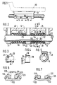
- FIG. 1 shows a schematic diagram of an actuating device according to the invention in view
- FIG. 2 shows a nut holder belonging to the actuating device, assembled and ready for use, in longitudinal section, in an enlarged view
- FIG 3 shows a cross section along the line VV in FIG. 2, through the unmounted nut holder, on a smaller scale than in FIG. 2
- FIG. 6 shows an enlarged partial principle view of the spindle mounted in the partial nuts , in a resulting assembly position on average
- FIG. 7 shows the arrangement according to FIG. 6 in the required operating position.
- a frame 10 of the seat of a motor vehicle, shown in dash-dotted lines in FIG. 1, is firmly connected to a nut holder 12.
- the mother carrier 12 has two chambers 14 and 16 for receiving each a partial nut 18, 20.
- the two partial nuts 18 and 20 work together with a threaded spindle 22 which passes through the nut holder 12 in the longitudinal direction.
- the seat is adjustable in the longitudinal direction of the vehicle.
- the adjustment device described in more detail below can also be used, for example, for a so-called seat height adjustment.
- the two partial nuts 18 and 20, since they are completely identical with regard to the spindle 22, can be referred to in their entirety as a single nut.
- the two partial nuts 18 and 20 are of the same design. Their arrangement in the two chambers 14 and 16 is directed against each other. The further arrangement and configuration of the two partial nuts 18 and 20 in their chambers 14 and 16 is to take place on the basis of the partial nut 20 arranged in the chamber 16.
- This partial nut, and a sleeve belonging to it, are shown as individual parts in FIGS. 3 and 4.
- the partial nut 20 is made of a plastic. It has a sleeve-like structure which is provided with an annular collar 24 on its circumference. The ring collar is penetrated by a number of longitudinal grooves 26, so that there are attachment points for a tool for rotating the part nut.
- a sleeve 28 is matched to the outer diameter of the partial nut 20 and can therefore be pushed over it until it strikes the collar 24.
- the sleeve 28 has as a shaped profile on its one end ring surface 30 a plurality of teeth 32 directed in the direction of displacement, which engage the grooves 26 of the annular collar 24 with a corresponding orientation of the sleeve 28, which thus form a counter profile.
- the partial nut 20 On its end facing away from the sleeve 28, the partial nut 20 is provided with a shoulder 34, the diameter of which is smaller than the inside diameter of the sleeve 28 or the outside diameter assigned to it of the partial nut 20.
- the sleeve 28 has two notches 36 on its circumference, so that there is a tab 38 which is bent outwards at an angle of approximately 90 degrees to the longitudinal axis of the sleeve from the outer surface of the sleeve 28.
- This tab 38 engages in the assembled state of the partial nut 20 and the sleeve 28 in a groove-like recess 40 which extends from the chamber 16 into the body of the nut holder 12.
- the tab 38 thus forms an anti-rotation device for the sleeve 28 (FIG. 5).
- an annular cap 42 which has a central opening for the threaded spindle 22, sits on the extension 34 of the partial nut 20.
- the ring cap 42 has an outwardly directed ring edge 44 which comes into contact with the ring collar 24 of the partial nut 20 when the ring cap 42 is mounted.
- a cup-shaped, second cap 46 is placed on the ring cap 42, the cup edge 48 of which comes to rest on the ring collar 44 of the first cap 42 before the pot base 49 of the second cap 46 rests on the base 51 of the first cap 42
- FIG. 2 further shows that the longitudinal extent of the sleeve 28 is somewhat smaller than the longitudinal extent of the partial nut 20 in the region which is overlapped by the sleeve 28 when it comes to rest on the side edges of the annular collar 24 facing it. This fact can be seen in particular in FIG. 2, where the position of the sleeve relative to the partial nut 20 just described is shown.
- the partial nut 20 is enclosed on the side facing away from the annular collar 24 by an annular securing element 52 which prevents axial movement of the sleeve 28.
- the assembly of the securing element 52 is made possible in that the ring 52 has a parting line which allows the securing element 52 made of an elastic material to be bent open. The locking ring 52 can therefore be removed from the position shown in Figure 2 without difficulty, so that a displacement of the sleeve 28 on the nut 20 is possible.
- FIG. 6 shows how the spindle 122 is arranged with respect to the two partial nuts 118 and 120. It can thus be seen that there is a longitudinal play 125 of the spindle 122 in the nut 118, 120 due to manufacturing tolerances in the thread. This longitudinal play 125 is the cause of the undesirable chattering phenomena described at the outset when the vehicle seat is adjusted. Around To eliminate this longitudinal play 125, the distance 127 existing between the two partial nuts 118, 120 must be increased by the size of the play 125; that is, the partial nut 118 must be moved in the direction of arrow 129 and / or the partial nut 120 in the direction of arrow 131. This measure is explained in more detail below with reference to FIG. 2.
- the locking ring 52 is removed from its mounting position shown in FIG. 2. Thereafter, the sleeve 28 is pushed in the direction of arrow 35 so that the teeth 32 come out of their grooves 26 of the collar 24. The displacement path of the sleeve 28 is therefore greater than the profile depth of the sleeve measured in the displacement direction. Then the partial nut 20 can be rotated with the aid of a tool that engages in the grooves 26 until the longitudinal play 125 between the flank of the threaded tooth 133 and the flank of the threaded groove 135 facing it is eliminated. The direction of rotation of the partial nut 120 is expediently such that the corrugated spring 50 is tensioned.
- the tension can of course also be set in such a way that a predetermined torque of the spindle in its threaded nut 18, 20 is achieved. Compression of the corrugated spring 50 at block height is excluded, however, because the annular collar 44 of the cap 42 comes to rest on the pot edge of the second cap 46 facing it.
- the sleeve 28 is returned against the arrow 35 into its assembly position shown in FIG.
- the teeth 32 engage again in the grooves 26 of the collar 24 of the partial nut 20 assigned to them.
- the locking ring 22 is brought back into its position shown in FIG becomes. Rotation of the sleeve 28 in the nut holder is prevented by the tab 38, which in cooperation with the groove-like recess 40 forms an anti-rotation device for the sleeve 28.
- the actuating device described has, as the output element, the threaded spindle 22 which cooperates with the threaded nut 18, 20 which acts as a counter element.
- the threaded nut 18, 20 is fixed. A slight change in the position of the partial nuts 18 and 20 in their chambers 14 and 16 is possible, but this displacement is within the scope of what the manufacturing tolerances of the mutually interacting threads of the spindle 22 and nut 18, 20 allow. In practice, this is at most 0.1 to 0.3 mm, which in no way can be described as a change in position in the usual sense.
- the threaded nut 18, 20 is formed from two partial nuts, so that two nut sections result. From the foregoing, it can also be seen that to cancel the longitudinal play 125, a nut section can be changed in position and fixed in relation to another nut section.
Landscapes
- Engineering & Computer Science (AREA)
- Aviation & Aerospace Engineering (AREA)
- Transportation (AREA)
- Mechanical Engineering (AREA)
- Transmission Devices (AREA)
- Seats For Vehicles (AREA)
Applications Claiming Priority (2)
| Application Number | Priority Date | Filing Date | Title |
|---|---|---|---|
| DE3843030 | 1988-12-21 | ||
| DE3843030A DE3843030C1 (enExample) | 1988-12-21 | 1988-12-21 |
Publications (2)
| Publication Number | Publication Date |
|---|---|
| EP0375842A1 EP0375842A1 (de) | 1990-07-04 |
| EP0375842B1 true EP0375842B1 (de) | 1992-06-03 |
Family
ID=6369726
Family Applications (1)
| Application Number | Title | Priority Date | Filing Date |
|---|---|---|---|
| EP89116905A Expired - Lifetime EP0375842B1 (de) | 1988-12-21 | 1989-09-13 | Einrichtung zum Verstellen eines Sitzes in einem Kraftfahrzeug |
Country Status (3)
| Country | Link |
|---|---|
| EP (1) | EP0375842B1 (enExample) |
| DE (2) | DE3843030C1 (enExample) |
| ES (1) | ES2032638T3 (enExample) |
Families Citing this family (3)
| Publication number | Priority date | Publication date | Assignee | Title |
|---|---|---|---|---|
| DE4330367B4 (de) * | 1993-09-08 | 2004-09-16 | Robert Bosch Gmbh | Vorrichtung zum motorischen Längsverstellen eines Sitzes in einem Kraftfahrzeug |
| DE10056443B4 (de) * | 2000-11-14 | 2004-09-30 | Keiper Gmbh & Co. Kg | Längseinsteller für einen Fahrzeugsitz |
| FR2837148B1 (fr) * | 2002-03-18 | 2004-07-02 | Faurecia Sieges Automobile | Mecanisme de reglage pour glissiere de siege de vehicule automobile ainsi que glissiere et siege equipes d'un tel mecanisme |
Family Cites Families (4)
| Publication number | Priority date | Publication date | Assignee | Title |
|---|---|---|---|---|
| DE3102402A1 (de) * | 1981-01-26 | 1982-09-16 | Metallwerk Max Brose Gmbh & Co, 8630 Coburg | Sitzverstellung, insbesondere fuer einen kraftfahrzeugsitz |
| DE3300654A1 (de) * | 1983-01-11 | 1984-07-12 | FAG Kugelfischer Georg Schäfer KGaA, 8720 Schweinfurt | Vorrichtung zur drehsicherung von zwei gegeneinander axial vorgespannten muttern eines gewindetriebs |
| FR2610063B1 (fr) * | 1987-01-27 | 1991-01-25 | Faure Ste Financiere Bertrand | Perfectionnements aux mecanismes de reglage de position a vis |
| DE3914378A1 (de) * | 1989-04-29 | 1990-11-08 | Basf Ag | Verfahren zum faerben von papier |
-
1988
- 1988-12-21 DE DE3843030A patent/DE3843030C1/de not_active Expired - Lifetime
-
1989
- 1989-09-13 EP EP89116905A patent/EP0375842B1/de not_active Expired - Lifetime
- 1989-09-13 DE DE8989116905T patent/DE58901608D1/de not_active Expired - Lifetime
- 1989-09-13 ES ES198989116905T patent/ES2032638T3/es not_active Expired - Lifetime
Also Published As
| Publication number | Publication date |
|---|---|
| DE58901608D1 (de) | 1992-07-09 |
| EP0375842A1 (de) | 1990-07-04 |
| ES2032638T3 (es) | 1993-02-16 |
| DE3843030C1 (enExample) | 1990-06-13 |
Similar Documents
| Publication | Publication Date | Title |
|---|---|---|
| EP0370212B1 (de) | Mutter mit Druckring | |
| DE4407854B4 (de) | Bohrfutter | |
| DE1289374B (de) | Rohrverbindungsstueck fuer Hochdruckleitungen | |
| DE3420528A1 (de) | Stufenlos verstellbare hubvorrichtung | |
| DE3610284A1 (de) | Antriebsmechanismus mit einer gewindespindel und spindelmutter | |
| DE2239853C3 (de) | Haltevorrichtung für Außenrückblickspiegel von Kraftfahrzeugen o.dgl | |
| DE3031216C2 (de) | Spannfutter für Gewindebohrer | |
| EP2594367A1 (de) | Schraubwerkzeug mit einer Vorrichtung zur Begrenzung des übertragenen Drehmomentes | |
| DE3538675C2 (enExample) | ||
| DE19829955A1 (de) | Verbinder zur Verwendung in einer Kupplungsvorrichtung | |
| DE19605894C1 (de) | Verfahren zur Herstellung einer Vorrichtung zum Verbinden eines Kerbverzahnten, der Übertragung von Drehmomenten dienenden Wellenzapfens | |
| DE3520417C2 (de) | Vorrichtung zum lösbaren Befestigen eines scheibenförmigen Werkzeugs, vorzugsweise einer Schleifscheibe oder dgl., an der Arbeitsspindel eines kraftgetriebenen Handwerkzeugs | |
| EP0275441B1 (de) | Spannvorrichtung | |
| DE3923131A1 (de) | Befestigungselement, insbesondere fuer eine kugel-gewindespindel | |
| DE2328113C3 (de) | Stellknopf | |
| DE20119267U1 (de) | Exzenter-Druckplatten für Federspanner | |
| EP1469208A1 (de) | Schraubelement mit einem angeformten Federelement | |
| EP0375842B1 (de) | Einrichtung zum Verstellen eines Sitzes in einem Kraftfahrzeug | |
| DE3335196C1 (de) | Spannvorrichtung für verzahnte Werkstücke | |
| DE3204919C1 (de) | Kugelgewindetrieb | |
| DE4228946C2 (de) | Spindelkopf für Werkzeugrevolver | |
| EP0205733A1 (de) | Schraubverbindung | |
| EP0921338A1 (de) | Signalgeber für einen Stellantrieb | |
| DE8817127U1 (de) | Vorrichtung zum Verstellen eines Sitzes in einem Kraftfahrzeug | |
| DE3802154C2 (enExample) |
Legal Events
| Date | Code | Title | Description |
|---|---|---|---|
| PUAI | Public reference made under article 153(3) epc to a published international application that has entered the european phase |
Free format text: ORIGINAL CODE: 0009012 |
|
| AK | Designated contracting states |
Kind code of ref document: A1 Designated state(s): DE ES FR GB IT SE |
|
| 17P | Request for examination filed |
Effective date: 19901126 |
|
| 17Q | First examination report despatched |
Effective date: 19910923 |
|
| RAP3 | Party data changed (applicant data changed or rights of an application transferred) |
Owner name: ROBERT BOSCH GMBH |
|
| GRAA | (expected) grant |
Free format text: ORIGINAL CODE: 0009210 |
|
| AK | Designated contracting states |
Kind code of ref document: B1 Designated state(s): DE ES FR GB IT SE |
|
| GBT | Gb: translation of ep patent filed (gb section 77(6)(a)/1977) | ||
| REF | Corresponds to: |
Ref document number: 58901608 Country of ref document: DE Date of ref document: 19920709 |
|
| RBV | Designated contracting states (corrected) |
Designated state(s): ES FR GB IT SE |
|
| ET | Fr: translation filed | ||
| ITF | It: translation for a ep patent filed | ||
| REG | Reference to a national code |
Ref country code: ES Ref legal event code: FG2A Ref document number: 2032638 Country of ref document: ES Kind code of ref document: T3 |
|
| PLBE | No opposition filed within time limit |
Free format text: ORIGINAL CODE: 0009261 |
|
| STAA | Information on the status of an ep patent application or granted ep patent |
Free format text: STATUS: NO OPPOSITION FILED WITHIN TIME LIMIT |
|
| 26N | No opposition filed | ||
| PGFP | Annual fee paid to national office [announced via postgrant information from national office to epo] |
Ref country code: GB Payment date: 19930903 Year of fee payment: 5 |
|
| PGFP | Annual fee paid to national office [announced via postgrant information from national office to epo] |
Ref country code: ES Payment date: 19930908 Year of fee payment: 5 |
|
| PGFP | Annual fee paid to national office [announced via postgrant information from national office to epo] |
Ref country code: FR Payment date: 19930930 Year of fee payment: 5 |
|
| PGFP | Annual fee paid to national office [announced via postgrant information from national office to epo] |
Ref country code: SE Payment date: 19931012 Year of fee payment: 5 |
|
| PGFP | Annual fee paid to national office [announced via postgrant information from national office to epo] |
Ref country code: GR Payment date: 19940223 Year of fee payment: 5 |
|
| PG25 | Lapsed in a contracting state [announced via postgrant information from national office to epo] |
Ref country code: GB Effective date: 19940913 |
|
| PG25 | Lapsed in a contracting state [announced via postgrant information from national office to epo] |
Ref country code: SE Effective date: 19940914 Ref country code: ES Free format text: LAPSE BECAUSE OF THE APPLICANT RENOUNCES Effective date: 19940914 |
|
| EAL | Se: european patent in force in sweden |
Ref document number: 89116905.4 |
|
| GBPC | Gb: european patent ceased through non-payment of renewal fee |
Effective date: 19940913 |
|
| PG25 | Lapsed in a contracting state [announced via postgrant information from national office to epo] |
Ref country code: FR Effective date: 19950531 |
|
| EUG | Se: european patent has lapsed |
Ref document number: 89116905.4 |
|
| REG | Reference to a national code |
Ref country code: FR Ref legal event code: ST |
|
| REG | Reference to a national code |
Ref country code: ES Ref legal event code: FD2A Effective date: 19991007 |
|
| PG25 | Lapsed in a contracting state [announced via postgrant information from national office to epo] |
Ref country code: IT Free format text: LAPSE BECAUSE OF NON-PAYMENT OF DUE FEES;WARNING: LAPSES OF ITALIAN PATENTS WITH EFFECTIVE DATE BEFORE 2007 MAY HAVE OCCURRED AT ANY TIME BEFORE 2007. THE CORRECT EFFECTIVE DATE MAY BE DIFFERENT FROM THE ONE RECORDED. Effective date: 20050913 |