EP0374902A2 - Système de microphones pour déterminer la direction et la position d'une source sonore - Google Patents
Système de microphones pour déterminer la direction et la position d'une source sonore Download PDFInfo
- Publication number
- EP0374902A2 EP0374902A2 EP89123591A EP89123591A EP0374902A2 EP 0374902 A2 EP0374902 A2 EP 0374902A2 EP 89123591 A EP89123591 A EP 89123591A EP 89123591 A EP89123591 A EP 89123591A EP 0374902 A2 EP0374902 A2 EP 0374902A2
- Authority
- EP
- European Patent Office
- Prior art keywords
- microphone
- sound
- microphone body
- microphones
- sound source
- Prior art date
- Legal status (The legal status is an assumption and is not a legal conclusion. Google has not performed a legal analysis and makes no representation as to the accuracy of the status listed.)
- Granted
Links
Images


Classifications
-
- H—ELECTRICITY
- H04—ELECTRIC COMMUNICATION TECHNIQUE
- H04R—LOUDSPEAKERS, MICROPHONES, GRAMOPHONE PICK-UPS OR LIKE ACOUSTIC ELECTROMECHANICAL TRANSDUCERS; DEAF-AID SETS; PUBLIC ADDRESS SYSTEMS
- H04R1/00—Details of transducers, loudspeakers or microphones
- H04R1/20—Arrangements for obtaining desired frequency or directional characteristics
- H04R1/32—Arrangements for obtaining desired frequency or directional characteristics for obtaining desired directional characteristic only
- H04R1/34—Arrangements for obtaining desired frequency or directional characteristics for obtaining desired directional characteristic only by using a single transducer with sound reflecting, diffracting, directing or guiding means
- H04R1/38—Arrangements for obtaining desired frequency or directional characteristics for obtaining desired directional characteristic only by using a single transducer with sound reflecting, diffracting, directing or guiding means in which sound waves act upon both sides of a diaphragm and incorporating acoustic phase-shifting means, e.g. pressure-gradient microphone
-
- G—PHYSICS
- G01—MEASURING; TESTING
- G01S—RADIO DIRECTION-FINDING; RADIO NAVIGATION; DETERMINING DISTANCE OR VELOCITY BY USE OF RADIO WAVES; LOCATING OR PRESENCE-DETECTING BY USE OF THE REFLECTION OR RERADIATION OF RADIO WAVES; ANALOGOUS ARRANGEMENTS USING OTHER WAVES
- G01S3/00—Direction-finders for determining the direction from which infrasonic, sonic, ultrasonic, or electromagnetic waves, or particle emission, not having a directional significance, are being received
- G01S3/80—Direction-finders for determining the direction from which infrasonic, sonic, ultrasonic, or electromagnetic waves, or particle emission, not having a directional significance, are being received using ultrasonic, sonic or infrasonic waves
- G01S3/801—Details
-
- G—PHYSICS
- G01—MEASURING; TESTING
- G01V—GEOPHYSICS; GRAVITATIONAL MEASUREMENTS; DETECTING MASSES OR OBJECTS; TAGS
- G01V1/00—Seismology; Seismic or acoustic prospecting or detecting
- G01V1/001—Acoustic presence detection
-
- H—ELECTRICITY
- H04—ELECTRIC COMMUNICATION TECHNIQUE
- H04R—LOUDSPEAKERS, MICROPHONES, GRAMOPHONE PICK-UPS OR LIKE ACOUSTIC ELECTROMECHANICAL TRANSDUCERS; DEAF-AID SETS; PUBLIC ADDRESS SYSTEMS
- H04R1/00—Details of transducers, loudspeakers or microphones
- H04R1/08—Mouthpieces; Microphones; Attachments therefor
- H04R1/083—Special constructions of mouthpieces
-
- H—ELECTRICITY
- H04—ELECTRIC COMMUNICATION TECHNIQUE
- H04R—LOUDSPEAKERS, MICROPHONES, GRAMOPHONE PICK-UPS OR LIKE ACOUSTIC ELECTROMECHANICAL TRANSDUCERS; DEAF-AID SETS; PUBLIC ADDRESS SYSTEMS
- H04R1/00—Details of transducers, loudspeakers or microphones
- H04R1/20—Arrangements for obtaining desired frequency or directional characteristics
- H04R1/32—Arrangements for obtaining desired frequency or directional characteristics for obtaining desired directional characteristic only
- H04R1/40—Arrangements for obtaining desired frequency or directional characteristics for obtaining desired directional characteristic only by combining a number of identical transducers
- H04R1/406—Arrangements for obtaining desired frequency or directional characteristics for obtaining desired directional characteristic only by combining a number of identical transducers microphones
Definitions
- the invention relates to a microphone system for determining the direction and position of a sound source.
- the predominantly used microphones register the sound pressure of a sound signal emanating from a sound source. Since the sound pressure is a scalar quantity, the directional information of the sound signal, which is a statement about the position of the signal source, is lost in these “pressure” microphones.
- Double microphones are used with which the sound pressure and the temporal pressure gradient as well as the sound speed are recorded. Extreme demands on the equality of the microphones have to be met. To measure the directional distribution of a sound field emanating from a sound source, it is necessary to scan the entire solid angle with the microphone axis.
- the invention has for its object to provide a microphone system that is suitable for the sound pressure gradient and the sound velocity Measure the amount, phase and direction so that the position of sound sources can be determined and vector intensity measurements are possible.
- This microphone system is said to be suitable for the measurement of sound waves in gaseous, liquid and solid media and can also be used as a hydrophone or geophone, for example.
- a single microphone with a microphone body preferably a ball
- the microphone body being exposed to the sound field to be measured and the oscillating movement of the microphone body induced by the sound field with vibration sensors built into it, e.g. . Accelerometers is measured.
- the vibration acceleration is a measure of the sound pressure gradient and can be calibrated to this and also to the local sound velocity.
- the direction of a sound source at least three vibration sensors sensitive to the three spatial directions are necessary.
- one or more conventional sound pressure microphones are additionally arranged in the surface of the microphone body.
- the registration of the sound pressure and the speed of sound makes it possible to determine the vectorial sound intensity.
- the microphone according to the invention can also be designed to be frequency-selective. There is a natural sensitivity maximum at the frequency whose half wavelength corresponds to the diameter of the microphone body. In this case there are opposing pressure conditions on the front and the back of the microphone body. An additional increase in resonance occurs when the microphone body is connected via spring coupling to a counterweight, which is preferably suspended elastically within the microphone body. Such an arrangement represents a single-track oscillator with an adjustable resonance frequency and self-damping. approximate the subjective amplitude rating.
- a cylindrical microphone body instead of a ball may be sufficient.
- the vibration sensors are distributed over the circumference of the cylinder.
- the direction finding base is determined by the spatial distance of the vibration sensors.
- this DF base it is possible to arrange a plurality of such microphones in a spatial pattern, a so-called array, wherein the individual microphone bodies can be the same or different in size at the same time.
- this increases the DF base and thus the DF accuracy, and on the other hand - by staggering the microphone body sizes - increases the frequency selectivity.
- FIGS. 1 to 6 each schematically show an exemplary embodiment of a microphone or a microphone arrangement according to the invention.
- FIG. 1 shows the basic design of a microphone according to the invention, with which both the sound pressure and the sound speed can be measured, so that this microphone can be referred to as a gradient microphone.
- This microphone is marked with 1a. It has a microphone body 2, in this case a ball, which is mounted on a microphone stand 4 via an elastic holder 3, for example one or more springs. A plurality of vibration sensors 5 are arranged on the surface of the ball 2, for example acceleration sensors, displacement and / or speed sensors, etc. sensitive in the three spatial directions.
- the ball shape of the microphone body 2 is exemplary here; microphone bodies in the form of a polyhedron can also be used.
- the dimensions of the microphone body 2 should be comparable to the wavelength of the highest frequency still to be registered of a sound source to be recorded.
- the internal natural frequencies of the microphone body 2 should lie above the frequency range to be measured.
- the microphone body 2 If the microphone body 2 is exposed to a sound field, it experiences a mechanical oscillating movement on its surface due to the different sound pressures, which is measured with the aid of the spatially oriented vibration sensors 5 which are firmly connected to the microphone body 2. In this way, the vectorial sound originating from a sound source can be determined in a pressure gradient. If several sound sources are to be determined simultaneously with respect to direction and position with this gradient microphone 1a, at least one group of three non-collinear vibration sensors must be provided for each sound source.
- a gradient microphone 1b is shown in FIG. 2 in the same schematic representation as in FIG. 1a.
- This gradient microphone 1b differs from that only in that one or more conventional microphones 6, which respond to the sound pressure, are arranged in the surface of the spherical microphone body 2. Together with the gradient and fast signal supplied by the gradient microphone 1a according to FIG. 1, the vectorial sound intensity can then be calibrated and determined using the microphone according to FIG. 2.
- FIG. 3 schematically shows a gradient microphone 1c, which is constructed like the gradient microphone 1a in FIG. 1.
- the spherical microphone body 2 is enclosed in a contact-free manner by a sound-permeable wind screen 7, which in turn is connected to the microphone stand 4.
- the wind screen 7 is e.g. from a single or multi-layer foam, sieve or foil jacket.
- the gradient microphone 1d shown schematically in Fig. 4 has a microphone body 2, which is composed of an outer microphone body 2 'and a counter mass 2 ⁇ arranged within this microphone body.
- the two masses 2 'and 2 ⁇ are connected to each other via several springs 8.
- vibration sensors 5 and Sound pressure microphones 6 integrated in the outer microphone body 2 ', as in the microphones described above, vibration sensors 5 and Sound pressure microphones 6 integrated.
- the outer microphone body 2 ' is in turn connected to the microphone stand 4 via elastic holders 3.
- This system represents a resonance system which has the same resonance frequency in all three spatial directions by appropriate adjustment of the spring constants of the elastic supports.
- Such a system is preferably excited by an external sound field at its resonance frequency. In this way, a desired frequency response, for example the evaluation of the frequency approximated to the human ear, can be set.
- additional vibration sensors 9 which are integrated in the counter mass 2 ⁇ , spectral suppression can be achieved by means of anti-resonance phenomena.
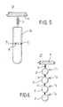
- a simplified form of a gradient microphone 1e shown in FIG. 5 can be used.
- the microphone body consists of a cylinder piece 1e, which in turn is connected to the microphone housing 4 via an elastic holder 3.
- Vibration pickups 5 and possibly sound pressure microphones 6 are provided on the circumference of the cylinder piece 2e.
- a gradient microphone arrangement 1f of several gradient microphones 11, 12, 13 and 14 is shown, which are arranged along a line.
- Each gradient microphone has a microphone body 2, which is equipped with vibration sensors and possibly sound pressure microphones in accordance with the above explanations.
- the individual microphone bodies 2 are each connected to a microphone stand 4 via elastic mounts 3, wherein a separate housing can be provided for each gradient microphone.
- the microphone bodies of the individual gradient microphones are in each case one below the other and only the two outer microphone bodies by elastic holders 3 a common microphone stand 4 are connected.
- This arrangement in an array increases the directional base of the microphone arrangement 1f. A different frequency range can additionally be encompassed by different diameters of the microphone bodies 2.
Applications Claiming Priority (2)
| Application Number | Priority Date | Filing Date | Title |
|---|---|---|---|
| DE19883843034 DE3843034A1 (de) | 1988-12-21 | 1988-12-21 | Mikrofonsystem zum bestimmen der richtung und position einer schallquelle |
| DE3843034 | 1988-12-21 |
Publications (3)
| Publication Number | Publication Date |
|---|---|
| EP0374902A2 true EP0374902A2 (fr) | 1990-06-27 |
| EP0374902A3 EP0374902A3 (fr) | 1991-12-18 |
| EP0374902B1 EP0374902B1 (fr) | 1995-04-19 |
Family
ID=6369730
Family Applications (1)
| Application Number | Title | Priority Date | Filing Date |
|---|---|---|---|
| EP19890123591 Expired - Lifetime EP0374902B1 (fr) | 1988-12-21 | 1989-12-20 | Système de microphones pour déterminer la direction et la position d'une source sonore |
Country Status (2)
| Country | Link |
|---|---|
| EP (1) | EP0374902B1 (fr) |
| DE (1) | DE3843034A1 (fr) |
Cited By (12)
| Publication number | Priority date | Publication date | Assignee | Title |
|---|---|---|---|---|
| EP0869697A2 (fr) * | 1997-04-03 | 1998-10-07 | Lucent Technologies Inc. | Réseau de microphones différentiels de premier ordre orientable et variable |
| EP1017249A1 (fr) * | 1998-12-31 | 2000-07-05 | Arkamys | Procédé et dispositif destinés à la prise de sons, à leur enregistrement et à leur restitution, et reproduisant la sensation naturelle d'espace sonore |
| WO2001074117A1 (fr) * | 2000-03-24 | 2001-10-04 | Intel Corporation | Systeme de commande sonore spatial |
| WO2003075605A1 (fr) * | 2002-03-01 | 2003-09-12 | Charles Whitman Fox | Réseau de microphones modulaires pour enregistrement ambiophonique |
| US7146014B2 (en) | 2002-06-11 | 2006-12-05 | Intel Corporation | MEMS directional sensor system |
| EP1737268A1 (fr) * | 2005-06-23 | 2006-12-27 | AKG Acoustics GmbH | Microphones à champ sonore |
| WO2007051925A1 (fr) * | 2005-11-04 | 2007-05-10 | Philippe Chenevez | Dispositifs de protection anti-vibratoire pour microphone |
| WO2011003651A1 (fr) * | 2009-07-07 | 2011-01-13 | Siemens Aktiengesellschaft | Réception d'ondes de pression, et reproduction à quantification directe |
| US8345898B2 (en) | 2008-02-26 | 2013-01-01 | Akg Acoustics Gmbh | Transducer assembly |
| US8472639B2 (en) | 2007-11-13 | 2013-06-25 | Akg Acoustics Gmbh | Microphone arrangement having more than one pressure gradient transducer |
| EP3525478A1 (fr) * | 2018-02-08 | 2019-08-14 | Audio-Technica Corporation | Dispositif de microphone |
| CN116132861A (zh) * | 2023-04-04 | 2023-05-16 | 恩平市奥新电子科技有限公司 | 一种可调节的麦克风架 |
Families Citing this family (1)
| Publication number | Priority date | Publication date | Assignee | Title |
|---|---|---|---|---|
| DE10217822C1 (de) | 2002-04-17 | 2003-09-25 | Daimler Chrysler Ag | Verfahren und Vorrichtung zur Blickrichtungserkennung einer Person mittels wenigstens eines richtungsselektiven Mikrofons |
Citations (4)
| Publication number | Priority date | Publication date | Assignee | Title |
|---|---|---|---|---|
| US2325424A (en) * | 1941-01-29 | 1943-07-27 | Rca Corp | Windshield for microphones |
| US2515031A (en) * | 1948-03-31 | 1950-07-11 | Bell Telephone Labor Inc | Microphone having controllable directional response pattern |
| US2810786A (en) * | 1950-06-12 | 1957-10-22 | Siemens Ag | Directional microphone system |
| US4703506A (en) * | 1985-07-23 | 1987-10-27 | Victor Company Of Japan, Ltd. | Directional microphone apparatus |
Family Cites Families (10)
| Publication number | Priority date | Publication date | Assignee | Title |
|---|---|---|---|---|
| DE867405C (de) * | 1945-04-04 | 1953-02-16 | Klangfilm Gmbh | Kondensator-Mikrofon mit federnd gehalterter Kapsel |
| DE836499C (de) * | 1949-11-01 | 1952-04-15 | Telefunken Gmbh | Mikrofonanordnung |
| US3004103A (en) * | 1958-12-22 | 1961-10-10 | Chance Vought Corp | Noise-reducing microphone assembly |
| DE1951446B2 (de) * | 1969-10-13 | 1972-09-07 | Sennheiser electronic Dr Ing Fritz Sennheiser, 3002 Wennebostel | Windschutz fuer ein rohrrichtmikrofon |
| US3736557A (en) * | 1969-11-26 | 1973-05-29 | Arf Products Inc | Acoustic locator with array of microphones |
| DE2116573A1 (de) * | 1971-04-05 | 1972-10-19 | Tn | Korperschallkompensierendes Mikrofon |
| US4441503A (en) * | 1982-01-18 | 1984-04-10 | General Electric Company | Collimation of ultrasonic linear array transducer |
| JPS607296A (ja) * | 1983-06-24 | 1985-01-16 | Furuno Electric Co Ltd | 水中探知用超音波送受波器 |
| DE3447842A1 (de) * | 1984-12-29 | 1986-07-10 | Fried. Krupp Gmbh, 4300 Essen | Sonarbasis |
| DE3520398A1 (de) * | 1985-06-07 | 1986-12-11 | Fried. Krupp Gmbh, 4300 Essen | Verfahren und vorrichtung zum ausblenden von stoersignalen |
-
1988
- 1988-12-21 DE DE19883843034 patent/DE3843034A1/de active Granted
-
1989
- 1989-12-20 EP EP19890123591 patent/EP0374902B1/fr not_active Expired - Lifetime
Patent Citations (4)
| Publication number | Priority date | Publication date | Assignee | Title |
|---|---|---|---|---|
| US2325424A (en) * | 1941-01-29 | 1943-07-27 | Rca Corp | Windshield for microphones |
| US2515031A (en) * | 1948-03-31 | 1950-07-11 | Bell Telephone Labor Inc | Microphone having controllable directional response pattern |
| US2810786A (en) * | 1950-06-12 | 1957-10-22 | Siemens Ag | Directional microphone system |
| US4703506A (en) * | 1985-07-23 | 1987-10-27 | Victor Company Of Japan, Ltd. | Directional microphone apparatus |
Cited By (17)
| Publication number | Priority date | Publication date | Assignee | Title |
|---|---|---|---|---|
| EP0869697A2 (fr) * | 1997-04-03 | 1998-10-07 | Lucent Technologies Inc. | Réseau de microphones différentiels de premier ordre orientable et variable |
| EP0869697A3 (fr) * | 1997-04-03 | 1999-03-31 | Lucent Technologies Inc. | Réseau de microphones différentiels de premier ordre orientable et variable |
| EP1017249A1 (fr) * | 1998-12-31 | 2000-07-05 | Arkamys | Procédé et dispositif destinés à la prise de sons, à leur enregistrement et à leur restitution, et reproduisant la sensation naturelle d'espace sonore |
| US6782104B1 (en) | 1998-12-31 | 2004-08-24 | Arkamys | Method and device intended for the picking up of sounds, for their recording and their play-back, and reproducing the natural sensation of a sound space |
| WO2001074117A1 (fr) * | 2000-03-24 | 2001-10-04 | Intel Corporation | Systeme de commande sonore spatial |
| WO2003075605A1 (fr) * | 2002-03-01 | 2003-09-12 | Charles Whitman Fox | Réseau de microphones modulaires pour enregistrement ambiophonique |
| US7146014B2 (en) | 2002-06-11 | 2006-12-05 | Intel Corporation | MEMS directional sensor system |
| EP1737268A1 (fr) * | 2005-06-23 | 2006-12-27 | AKG Acoustics GmbH | Microphones à champ sonore |
| WO2007051925A1 (fr) * | 2005-11-04 | 2007-05-10 | Philippe Chenevez | Dispositifs de protection anti-vibratoire pour microphone |
| FR2893213A1 (fr) * | 2005-11-04 | 2007-05-11 | Philippe Francois Chenevez | Dispositifs de protection anti-vibratoire pour microphone. |
| US8472639B2 (en) | 2007-11-13 | 2013-06-25 | Akg Acoustics Gmbh | Microphone arrangement having more than one pressure gradient transducer |
| US8345898B2 (en) | 2008-02-26 | 2013-01-01 | Akg Acoustics Gmbh | Transducer assembly |
| WO2011003651A1 (fr) * | 2009-07-07 | 2011-01-13 | Siemens Aktiengesellschaft | Réception d'ondes de pression, et reproduction à quantification directe |
| EP3525478A1 (fr) * | 2018-02-08 | 2019-08-14 | Audio-Technica Corporation | Dispositif de microphone |
| US10536762B2 (en) | 2018-02-08 | 2020-01-14 | Audio-Technica Corporation | Microphone device and case for microphone device |
| US10951969B2 (en) | 2018-02-08 | 2021-03-16 | Audio-Technica Corporation | Case for microphone device |
| CN116132861A (zh) * | 2023-04-04 | 2023-05-16 | 恩平市奥新电子科技有限公司 | 一种可调节的麦克风架 |
Also Published As
| Publication number | Publication date |
|---|---|
| DE3843034C2 (fr) | 1992-10-01 |
| DE3843034A1 (de) | 1990-06-28 |
| EP0374902A3 (fr) | 1991-12-18 |
| EP0374902B1 (fr) | 1995-04-19 |
Similar Documents
| Publication | Publication Date | Title |
|---|---|---|
| EP0374902B1 (fr) | Système de microphones pour déterminer la direction et la position d'une source sonore | |
| DE3934745C1 (fr) | ||
| DE102007046031B4 (de) | Ultraschallsensor | |
| EP0359864A1 (fr) | Dispositif et procédé de mesure de champs magnétiques faibles, dépendant de la position et du temps | |
| EP1671086A1 (fr) | Capteur de vehicule pour determiner une acceleration et un bruit de structure | |
| DE10225714A1 (de) | Mehrachsiger monolithischer Beschleunigungssensor | |
| DE3843033C2 (fr) | ||
| DE3923740C1 (fr) | ||
| DE4294875C2 (de) | Schallkalibrator | |
| DE69433323T2 (de) | Flugzeugsensor zum abhören akustischer signale | |
| DE69825820T2 (de) | Miniaturisierter Beschleunigungssensor mit Kompensation der Schwerkraft mittels einer Feder sowie Verfahren zu seiner Herstellung | |
| DE2254272A1 (de) | Vorrichtung zum pruefen von fahrzeugfederungen | |
| DE60009211T2 (de) | Sensor für elastische Wellen, elektrisch kompensiert für Neigungs-Effekte | |
| DE69722969T2 (de) | Hydrophon mit statistischen druckkompensation und druckwellenmessverfahren | |
| DE3013684C2 (de) | Klopfsensor | |
| DE747008C (de) | Piezoelektrischer, beschleunigungsempfindlicher Geber | |
| DE4129447C2 (de) | Verfahren zur elektroakustischen Messung des Trefferwinkels vorbeifliegender Geschosse an Luftschleppzielen und Einrichtung zum Durchführen des Verfahrens | |
| DE60026782T2 (de) | Ultraschallsonde | |
| DE3819398C2 (fr) | ||
| EP0061808A2 (fr) | Dispositif d'examen de corps à structure périodique | |
| EP1480019A1 (fr) | Procédé et dispositif pour la mesure d'un débit massique | |
| DE2459194A1 (de) | Pruef- und kalibriervorrichtung fuer zumindest einen beschleunigungsaufnehmer | |
| DE2813487C2 (fr) | ||
| DE3809349C2 (fr) | ||
| DE1566434A1 (de) | Bett zur UEberwachung und Beobachtung eines Kranken |
Legal Events
| Date | Code | Title | Description |
|---|---|---|---|
| PUAI | Public reference made under article 153(3) epc to a published international application that has entered the european phase |
Free format text: ORIGINAL CODE: 0009012 |
|
| AK | Designated contracting states |
Kind code of ref document: A2 Designated state(s): ES FR GB IT NL |
|
| PUAL | Search report despatched |
Free format text: ORIGINAL CODE: 0009013 |
|
| AK | Designated contracting states |
Kind code of ref document: A3 Designated state(s): ES FR GB IT NL |
|
| 17P | Request for examination filed |
Effective date: 19920616 |
|
| 17Q | First examination report despatched |
Effective date: 19931029 |
|
| GRAA | (expected) grant |
Free format text: ORIGINAL CODE: 0009210 |
|
| AK | Designated contracting states |
Kind code of ref document: B1 Designated state(s): ES FR GB IT NL |
|
| PG25 | Lapsed in a contracting state [announced via postgrant information from national office to epo] |
Ref country code: IT Free format text: LAPSE BECAUSE OF FAILURE TO SUBMIT A TRANSLATION OF THE DESCRIPTION OR TO PAY THE FEE WITHIN THE PRESCRIBED TIME-LIMIT;WARNING: LAPSES OF ITALIAN PATENTS WITH EFFECTIVE DATE BEFORE 2007 MAY HAVE OCCURRED AT ANY TIME BEFORE 2007. THE CORRECT EFFECTIVE DATE MAY BE DIFFERENT FROM THE ONE RECORDED. Effective date: 19950419 Ref country code: ES Free format text: THE PATENT HAS BEEN ANNULLED BY A DECISION OF A NATIONAL AUTHORITY Effective date: 19950419 Ref country code: FR Effective date: 19950419 Ref country code: NL Free format text: LAPSE BECAUSE OF NON-PAYMENT OF DUE FEES Effective date: 19950419 Ref country code: GB Effective date: 19950419 |
|
| EN | Fr: translation not filed | ||
| NLV1 | Nl: lapsed or annulled due to failure to fulfill the requirements of art. 29p and 29m of the patents act | ||
| GBV | Gb: ep patent (uk) treated as always having been void in accordance with gb section 77(7)/1977 [no translation filed] |
Effective date: 19950419 |
|
| PLBE | No opposition filed within time limit |
Free format text: ORIGINAL CODE: 0009261 |
|
| STAA | Information on the status of an ep patent application or granted ep patent |
Free format text: STATUS: NO OPPOSITION FILED WITHIN TIME LIMIT |
|
| 26N | No opposition filed |