EP0373731A1 - Vorrichtung zum Verschliessen einer im wesentlichen aus einem Schlauchabschnitt aus einem Thermoplast bestehenden Öffnung - Google Patents
Vorrichtung zum Verschliessen einer im wesentlichen aus einem Schlauchabschnitt aus einem Thermoplast bestehenden Öffnung Download PDFInfo
- Publication number
- EP0373731A1 EP0373731A1 EP89250059A EP89250059A EP0373731A1 EP 0373731 A1 EP0373731 A1 EP 0373731A1 EP 89250059 A EP89250059 A EP 89250059A EP 89250059 A EP89250059 A EP 89250059A EP 0373731 A1 EP0373731 A1 EP 0373731A1
- Authority
- EP
- European Patent Office
- Prior art keywords
- nozzle head
- air outlet
- outlet openings
- parts
- essentially
- Prior art date
- Legal status (The legal status is an assumption and is not a legal conclusion. Google has not performed a legal analysis and makes no representation as to the accuracy of the status listed.)
- Withdrawn
Links
Images

Classifications
-
- B—PERFORMING OPERATIONS; TRANSPORTING
- B65—CONVEYING; PACKING; STORING; HANDLING THIN OR FILAMENTARY MATERIAL
- B65B—MACHINES, APPARATUS OR DEVICES FOR, OR METHODS OF, PACKAGING ARTICLES OR MATERIALS; UNPACKING
- B65B7/00—Closing containers or receptacles after filling
- B65B7/02—Closing containers or receptacles deformed by, or taking-up shape, of, contents, e.g. bags, sacks
- B65B7/025—Closing valve bags
-
- B—PERFORMING OPERATIONS; TRANSPORTING
- B29—WORKING OF PLASTICS; WORKING OF SUBSTANCES IN A PLASTIC STATE IN GENERAL
- B29C—SHAPING OR JOINING OF PLASTICS; SHAPING OF MATERIAL IN A PLASTIC STATE, NOT OTHERWISE PROVIDED FOR; AFTER-TREATMENT OF THE SHAPED PRODUCTS, e.g. REPAIRING
- B29C65/00—Joining or sealing of preformed parts, e.g. welding of plastics materials; Apparatus therefor
- B29C65/02—Joining or sealing of preformed parts, e.g. welding of plastics materials; Apparatus therefor by heating, with or without pressure
- B29C65/10—Joining or sealing of preformed parts, e.g. welding of plastics materials; Apparatus therefor by heating, with or without pressure using hot gases (e.g. combustion gases) or flames coming in contact with at least one of the parts to be joined
- B29C65/103—Joining or sealing of preformed parts, e.g. welding of plastics materials; Apparatus therefor by heating, with or without pressure using hot gases (e.g. combustion gases) or flames coming in contact with at least one of the parts to be joined direct heating both surfaces to be joined
-
- B—PERFORMING OPERATIONS; TRANSPORTING
- B29—WORKING OF PLASTICS; WORKING OF SUBSTANCES IN A PLASTIC STATE IN GENERAL
- B29C—SHAPING OR JOINING OF PLASTICS; SHAPING OF MATERIAL IN A PLASTIC STATE, NOT OTHERWISE PROVIDED FOR; AFTER-TREATMENT OF THE SHAPED PRODUCTS, e.g. REPAIRING
- B29C66/00—General aspects of processes or apparatus for joining preformed parts
- B29C66/01—General aspects dealing with the joint area or with the area to be joined
- B29C66/05—Particular design of joint configurations
- B29C66/10—Particular design of joint configurations particular design of the joint cross-sections
- B29C66/11—Joint cross-sections comprising a single joint-segment, i.e. one of the parts to be joined comprising a single joint-segment in the joint cross-section
- B29C66/112—Single lapped joints
- B29C66/1122—Single lap to lap joints, i.e. overlap joints
-
- B—PERFORMING OPERATIONS; TRANSPORTING
- B29—WORKING OF PLASTICS; WORKING OF SUBSTANCES IN A PLASTIC STATE IN GENERAL
- B29C—SHAPING OR JOINING OF PLASTICS; SHAPING OF MATERIAL IN A PLASTIC STATE, NOT OTHERWISE PROVIDED FOR; AFTER-TREATMENT OF THE SHAPED PRODUCTS, e.g. REPAIRING
- B29C66/00—General aspects of processes or apparatus for joining preformed parts
- B29C66/40—General aspects of joining substantially flat articles, e.g. plates, sheets or web-like materials; Making flat seams in tubular or hollow articles; Joining single elements to substantially flat surfaces
- B29C66/41—Joining substantially flat articles ; Making flat seams in tubular or hollow articles
- B29C66/43—Joining a relatively small portion of the surface of said articles
- B29C66/431—Joining the articles to themselves
- B29C66/4312—Joining the articles to themselves for making flat seams in tubular or hollow articles, e.g. transversal seams
- B29C66/43121—Closing the ends of tubular or hollow single articles, e.g. closing the ends of bags
- B29C66/43123—Closing the ends of squeeze tubes, e.g. for toothpaste or cosmetics
-
- B—PERFORMING OPERATIONS; TRANSPORTING
- B29—WORKING OF PLASTICS; WORKING OF SUBSTANCES IN A PLASTIC STATE IN GENERAL
- B29C—SHAPING OR JOINING OF PLASTICS; SHAPING OF MATERIAL IN A PLASTIC STATE, NOT OTHERWISE PROVIDED FOR; AFTER-TREATMENT OF THE SHAPED PRODUCTS, e.g. REPAIRING
- B29C66/00—General aspects of processes or apparatus for joining preformed parts
- B29C66/70—General aspects of processes or apparatus for joining preformed parts characterised by the composition, physical properties or the structure of the material of the parts to be joined; Joining with non-plastics material
- B29C66/71—General aspects of processes or apparatus for joining preformed parts characterised by the composition, physical properties or the structure of the material of the parts to be joined; Joining with non-plastics material characterised by the composition of the plastics material of the parts to be joined
-
- B—PERFORMING OPERATIONS; TRANSPORTING
- B29—WORKING OF PLASTICS; WORKING OF SUBSTANCES IN A PLASTIC STATE IN GENERAL
- B29C—SHAPING OR JOINING OF PLASTICS; SHAPING OF MATERIAL IN A PLASTIC STATE, NOT OTHERWISE PROVIDED FOR; AFTER-TREATMENT OF THE SHAPED PRODUCTS, e.g. REPAIRING
- B29C66/00—General aspects of processes or apparatus for joining preformed parts
- B29C66/70—General aspects of processes or apparatus for joining preformed parts characterised by the composition, physical properties or the structure of the material of the parts to be joined; Joining with non-plastics material
- B29C66/73—General aspects of processes or apparatus for joining preformed parts characterised by the composition, physical properties or the structure of the material of the parts to be joined; Joining with non-plastics material characterised by the intensive physical properties of the material of the parts to be joined, by the optical properties of the material of the parts to be joined, by the extensive physical properties of the parts to be joined, by the state of the material of the parts to be joined or by the material of the parts to be joined being a thermoplastic or a thermoset
- B29C66/739—General aspects of processes or apparatus for joining preformed parts characterised by the composition, physical properties or the structure of the material of the parts to be joined; Joining with non-plastics material characterised by the intensive physical properties of the material of the parts to be joined, by the optical properties of the material of the parts to be joined, by the extensive physical properties of the parts to be joined, by the state of the material of the parts to be joined or by the material of the parts to be joined being a thermoplastic or a thermoset characterised by the material of the parts to be joined being a thermoplastic or a thermoset
- B29C66/7392—General aspects of processes or apparatus for joining preformed parts characterised by the composition, physical properties or the structure of the material of the parts to be joined; Joining with non-plastics material characterised by the intensive physical properties of the material of the parts to be joined, by the optical properties of the material of the parts to be joined, by the extensive physical properties of the parts to be joined, by the state of the material of the parts to be joined or by the material of the parts to be joined being a thermoplastic or a thermoset characterised by the material of the parts to be joined being a thermoplastic or a thermoset characterised by the material of at least one of the parts being a thermoplastic
- B29C66/73921—General aspects of processes or apparatus for joining preformed parts characterised by the composition, physical properties or the structure of the material of the parts to be joined; Joining with non-plastics material characterised by the intensive physical properties of the material of the parts to be joined, by the optical properties of the material of the parts to be joined, by the extensive physical properties of the parts to be joined, by the state of the material of the parts to be joined or by the material of the parts to be joined being a thermoplastic or a thermoset characterised by the material of the parts to be joined being a thermoplastic or a thermoset characterised by the material of at least one of the parts being a thermoplastic characterised by the materials of both parts being thermoplastics
-
- B—PERFORMING OPERATIONS; TRANSPORTING
- B29—WORKING OF PLASTICS; WORKING OF SUBSTANCES IN A PLASTIC STATE IN GENERAL
- B29C—SHAPING OR JOINING OF PLASTICS; SHAPING OF MATERIAL IN A PLASTIC STATE, NOT OTHERWISE PROVIDED FOR; AFTER-TREATMENT OF THE SHAPED PRODUCTS, e.g. REPAIRING
- B29C66/00—General aspects of processes or apparatus for joining preformed parts
- B29C66/80—General aspects of machine operations or constructions and parts thereof
-
- B—PERFORMING OPERATIONS; TRANSPORTING
- B29—WORKING OF PLASTICS; WORKING OF SUBSTANCES IN A PLASTIC STATE IN GENERAL
- B29C—SHAPING OR JOINING OF PLASTICS; SHAPING OF MATERIAL IN A PLASTIC STATE, NOT OTHERWISE PROVIDED FOR; AFTER-TREATMENT OF THE SHAPED PRODUCTS, e.g. REPAIRING
- B29C66/00—General aspects of processes or apparatus for joining preformed parts
- B29C66/40—General aspects of joining substantially flat articles, e.g. plates, sheets or web-like materials; Making flat seams in tubular or hollow articles; Joining single elements to substantially flat surfaces
- B29C66/41—Joining substantially flat articles ; Making flat seams in tubular or hollow articles
- B29C66/43—Joining a relatively small portion of the surface of said articles
- B29C66/431—Joining the articles to themselves
- B29C66/4312—Joining the articles to themselves for making flat seams in tubular or hollow articles, e.g. transversal seams
-
- B—PERFORMING OPERATIONS; TRANSPORTING
- B29—WORKING OF PLASTICS; WORKING OF SUBSTANCES IN A PLASTIC STATE IN GENERAL
- B29K—INDEXING SCHEME ASSOCIATED WITH SUBCLASSES B29B, B29C OR B29D, RELATING TO MOULDING MATERIALS OR TO MATERIALS FOR MOULDS, REINFORCEMENTS, FILLERS OR PREFORMED PARTS, e.g. INSERTS
- B29K2023/00—Use of polyalkenes or derivatives thereof as moulding material
- B29K2023/04—Polymers of ethylene
- B29K2023/06—PE, i.e. polyethylene
Definitions
- the invention relates to a device for closing an opening consisting essentially of a thermoplastic, in particular polyethylene, in particular a filling opening in a packaging bag; with a hot air line and a nozzle head connected to it.
- bags or sacks In industrial production as bulk goods, everyday goods that reach the end consumer in smaller containers, such as animal feed, building materials, cat litter, etc., are usually filled and packaged in automatic packaging lines in bags or sacks. While these bags or sacks are smaller Containers, such as a bag for sugar or the like. are made of paper, the sacks for heavier containers, such as potting soil, peat or cat litter, are often made of plastic film.
- plastic sacks which are often made of a thermoplastic, such as polyethylene, are usually already folded and sealed, apart from a filling opening, which can also be arranged on the bottom of the sack, for example, in the interest of efficient filling or packaging, before being sealed on a filling machine the filling opening can be filled with the respective bulk material.
- a filling opening which can also be arranged on the bottom of the sack, for example, in the interest of efficient filling or packaging, before being sealed on a filling machine the filling opening can be filled with the respective bulk material.
- the filling opening of the plastic bag must be closed, the filling opening being particularly important for air-sensitive goods or for goods that should not get into the environment during a later transport of the filled plastic bag - be it for aesthetic or cost reasons as hermetically sealed as possible.
- the filling opening shaped in the form of a tube section is heated and then closed by welding the opposing walls, in which the tube section is pressed between two clamping jaws.
- the inner wall of the hose section or the filling opening is usually heated by hot air, for which purpose a nozzle head is introduced into the opening, which has a number of radially arranged air outlet openings directed towards the inner lateral surfaces of the opening.
- the heat energy introduced with the hot air softens the areas of the hose section or the filling opening which are acted upon by hot air and, after the nozzle head, which is generally axially displaceable, is pulled together by being compressed other welded.
- the tube section to be sealed can additionally be sealed with a thermoplastic film with a lower melting point than that of the other material from which the sack is made , be lined.
- the reason for the often poor quality of the weld seam closing the filling opening is, among other things. to be found in the fact that with conventional nozzle heads the heat cannot be introduced evenly enough into the areas of the inner jacket surfaces of the filling opening to be melted. This is mainly due to the fact that the diameter of a conventional nozzle head must be considerably smaller than the filling opening to be closed, since otherwise the molten plastic would come into contact with it when the nozzle head was pulled back and the filling opening and thus the entire sack would stick to the nozzle head.
- the temperature at the air outlet opening during processing of conventional polyethylene materials is 250 o to due to the cooling that the hot air flow experiences when this distance is covered 300 o C to set. Because of the associated, overall higher temperature level in the entire supply lines etc., it is evident that the radiation losses of the entire packaging machine are also significantly increased.
- the invention is accordingly based on the object of improving a device of the type mentioned at the outset in such a way that the quality of the weld seam closing an opening of the type described in a packaging bag is improved and the power to be expended is reduced.
- the solution to the problem is characterized in a generic device in that the nozzle head consists of at least two parts which are movable relative to each other.
- Another advantageous embodiment of the invention is characterized in that at least part of the nozzle head is mounted about an axis.
- Another advantageous embodiment of the invention is characterized in that the axis of the movable part of the nozzle head is arranged at right angles to the main axis of the nozzle head.
- a further advantageous embodiment of the invention is characterized in that the nozzle head has a plurality of air outlet openings which extend essentially radially from the main axis thereof.
- a further advantageous embodiment of the invention is characterized in that the air outlet openings are arranged essentially in a ring in one plane.
- Another advantageous embodiment of the invention is characterized in that the air outlet openings are arranged in a circumferential throat.
- a further advantageous embodiment of the invention is characterized in that at least one annular bead is arranged parallel to the air outlet openings arranged in a ring.
- a further advantageous embodiment of the invention is characterized in that the circumference of the nozzle head is variable in the area in which the air outlet openings are arranged.
- Another advantageous embodiment of the invention is characterized in that the nozzle head is axially movable overall in the direction of its main axis.
- nozzle head has an essentially cylindrical basic shape.
- a further advantageous embodiment of the invention is characterized in that the substantially cylindrical nozzle head consists of (at least two) parts, the cross section of which is essentially a sector of a circle, the central angle of which is a part of a full circle which is inversely proportional to the number of parts of the nozzle head.
- a further advantageous embodiment of the invention is characterized in that the substantially cylindrical nozzle head at one end adjoins the area of the Air outlet openings adjoining conical section.
- this has at least one ramp-shaped extension arranged at the end of the nozzle head facing away from the area of the air outlet openings, and a stop protruding in its direction of movement when the nozzle head is axially moved.
- Another advantageous embodiment of the invention is characterized in that the stop has a rotatably mounted roller.
- a further advantageous embodiment of the invention is characterized in that the nozzle head consists essentially of three parts, two of which are pivotable about axes arranged in the third (middle) part.
- Another advantageous embodiment of the invention is characterized in that the third component has essentially the shape of two interconnected plates, the (inner) distance from each other corresponds to the width of the other two parts, and that the axes of rotation of the other two parts are at right angles Plate to plate are arranged extending.
- this has at least one pressure plate coated with an elastic material.
- this has at least one pressure plate provided with an edge with a small radius of curvature.
- a nozzle head In a preferred embodiment of a nozzle head according to the invention, it has two parts arranged opposite one another, each of which can be rotated about an axis are mounted and each have one ramp-shaped extension at one end, which abut against a stop during the axial movement of the nozzle head, whereupon the relevant parts are spread apart like a beak. Due to the beak-like spreading of the nozzle head, it is enlarged, as it were, circumferentially and comes to rest on the inner wall of the filling opening to be closed.
- the air outlet openings which are preferably arranged in the form of a circular ring, are not closed and so that the melting plastic does not adhere to the nozzle head, provision can be made to arrange the air outlet openings in a circumferential throat.
- An annular bead sealing towards the inside of the bag can be provided parallel to the throat.
- the ring bulge facing away from the sack the diameter of which is preferably slightly smaller than the diameter of the first ring bulge, so that an annular gap remains between the inner wall of the opening to be closed and the second ring bulge mentioned, with appropriate dimensioning of the diameter of the second, generally.
- the ring bead lying at the top and the dimensioning of the remaining annular gap associated therewith the flow resistance of the entire arrangement of the nozzle head / filling opening can be set, so that the amount of air escaping at a certain operating pressure can be determined.
- a first pressure jaw can be coated with an elastic material, for example foam rubber, whereas the second pressure jaw, which represents the counterpart, has a comparatively sharp edge with a small radius of curvature. In this way, a high surface pressure is achieved in the heated area to be welded.
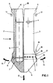
- a device has a variant of a nozzle head 1, which consists of two mirror-symmetrical halves or parts 2 and 3.
- the part 3 is rotatably mounted about an axis 4, as is the part 2 about a correspondingly arranged axis, not shown here.
- the entire shape of the nozzle head is approximately cylindrical, the cross section of a part 2 or 3 being essentially a semicircle.
- the lower end - the nozzle head changes into a cone 5.
- a throat 6 Between the central cylindrical part of the nozzle head and the cone 5 there is a throat 6, in which the air outlet openings 7 are arranged in a ring.
- the air outlet bores 7 are connected via channels 8 an inner cavity 9 which is present in parts 2 and 3 and which is connected via a schematically illustrated connecting piece 10 to a hot air line (not shown) and from which hot air is applied.
- both parts 2 and 3 each have a ramp-shaped extension 11. If the entire nozzle head is moved axially in the direction of arrow 12, the ramp-shaped extensions 11 come into engagement with stops 13, which can optionally also be designed as a rotatably mounted roller. When the nozzle head is moved further in the direction of the arrow 12, the halves 2 and 3 rotate about their respective axes, the nozzle head being spread out like a beak at its lower end in the direction of the arrows 14. If the spread is sufficiently wide, the halves 2 and 3, with an annular bead 15 located at the respective lower end parallel to the throat 6, rest against the wall 16 of the filling opening to be closed, which is shown here in an idealized manner.
- the hot air flowing through the cavities 9 and the respective channels 8 and exiting at the outlet openings 7 reaches an annular gap 17 formed between the wall 16 and the groove 6, where it is swirled and releases its heat to the cold wall 16.
- the air can escape in a controlled manner through a likewise annular gap 19 formed between a second annular bead 18 and the wall 16.
- a disadvantage of this nozzle head which is characterized by its simple structure, is that due to the gap remaining between the two halves or parts 2 and 3 in a spread state, part of the wall of the filling opening to be heated is not directly subjected to hot air. This deficiency can be remedied by a somewhat more complex construction of the nozzle head according to the invention, as shown in FIG. 2.
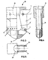
- the nozzle head 20 shown in Fig. 2 is characterized by a three-part structure, two wing-like arranged outer parts 2 'and 3' each about an axis 4 'and 4' are pivotally attached to a central part 21.
- the method of operation is completely analogous to the exemplary embodiment of a nozzle head according to the invention or a device according to the invention for closing an opening of the type mentioned in FIG. 1.
- a nozzle head arranged vertically as shown in FIG 'Or 3' can be achieved that this when moving back the nozzle head 20, ie return to its original position in the opposite direction to arrow 12 under the influence of gravity.
- FIG. 2 The inner structure of the three-part nozzle head shown in FIG. 2 is shown in more detail in FIGS. 3, 4 and 5, with the wing 2 'being omitted for the sake of clarity and the wing 3' being drawn in the folded position.
- the nozzle head 20 consists of an upwardly widening central part 21 which essentially has the basic geometric shape of two plates 23 and 24 which are connected to one another in a region 22. Arranged between these plates are the swing-out wings 3 'or the wing 2', not shown here. In the upper part of the middle piece 21, a bore 25 is provided for connecting the hot air line.
- the hot air flows through the bore 25 into the cavity 9 'formed by the individual components 2', 3 'and 21, and from there through the channels 8' to the outlet openings 7 arranged in a ring 6 in a circular circle.
- the air outlet openings 7 of a wing 3 'be arranged vertically at an angle so that the entirety of all air outlet openings with wings 2' or 3 'are approximately in one plane.
- the inventive design of a device for closing an opening in packaging material made of thermoplastic materials increases the quality of the weld seam closing the opening, while at the same time reducing the power to be used and thus the costs.
Landscapes
- Engineering & Computer Science (AREA)
- Mechanical Engineering (AREA)
- Chemical & Material Sciences (AREA)
- Combustion & Propulsion (AREA)
- Package Closures (AREA)
Applications Claiming Priority (2)
| Application Number | Priority Date | Filing Date | Title |
|---|---|---|---|
| DE3841450A DE3841450A1 (de) | 1988-12-09 | 1988-12-09 | Vorrichtung zum verschliessen einer im wesentlichen aus einem schlauchabschnitt aus einem thermoplast bestehenden oeffnung |
| DE3841450 | 1988-12-09 |
Publications (1)
| Publication Number | Publication Date |
|---|---|
| EP0373731A1 true EP0373731A1 (de) | 1990-06-20 |
Family
ID=6368765
Family Applications (1)
| Application Number | Title | Priority Date | Filing Date |
|---|---|---|---|
| EP89250059A Withdrawn EP0373731A1 (de) | 1988-12-09 | 1989-10-18 | Vorrichtung zum Verschliessen einer im wesentlichen aus einem Schlauchabschnitt aus einem Thermoplast bestehenden Öffnung |
Country Status (6)
| Country | Link |
|---|---|
| EP (1) | EP0373731A1 (enExample) |
| JP (1) | JPH0776020B2 (enExample) |
| AU (1) | AU4655589A (enExample) |
| BR (1) | BR8907222A (enExample) |
| DE (1) | DE3841450A1 (enExample) |
| WO (1) | WO1990006260A1 (enExample) |
Cited By (2)
| Publication number | Priority date | Publication date | Assignee | Title |
|---|---|---|---|---|
| GB2254285A (en) * | 1991-03-25 | 1992-10-07 | Tetra Pak Holdings Sa | Heat sealing carton blanks |
| WO2011077091A1 (en) * | 2009-12-23 | 2011-06-30 | Elopak Systems Ag | Improvements in or relating to heating devices and methods |
Families Citing this family (2)
| Publication number | Priority date | Publication date | Assignee | Title |
|---|---|---|---|---|
| DE4004817C2 (de) * | 1990-02-16 | 1994-12-22 | Haver & Boecker | Vorrichtung zum Schließen des Ventils eines mittels einer Füllmaschine gefüllten Ventilsackes |
| SE9300669D0 (sv) * | 1993-02-26 | 1993-02-26 | Norden Pac Dev Ab | Multi-tube packaging container and method of manufacture |
Citations (6)
| Publication number | Priority date | Publication date | Assignee | Title |
|---|---|---|---|---|
| US1939502A (en) * | 1931-03-09 | 1933-12-12 | James A Rheinstrom | Closing mechanism for collapsible tubes |
| FR1203466A (fr) * | 1958-10-06 | 1960-01-19 | Procédé de fermeture de récipients en matière plastique | |
| GB859554A (en) * | 1958-07-04 | 1961-01-25 | Agfa Ag | A method of and apparatus for sealing plastic containers |
| FR2278962A1 (fr) * | 1973-05-25 | 1976-02-13 | Hurdequint Louis | Soufflerie a air chaud destinee, en particulier, a la retraction de films d'emballage |
| GB2134037A (en) * | 1983-01-20 | 1984-08-08 | Norden Packaging Mach | Hot gas welding device |
| DE3442187A1 (de) * | 1984-03-16 | 1986-05-28 | Haver & Boecker, 4740 Oelde | Vorrichtung zum schliessen des ventils eines mittels einer fuellmaschine gefuellten sackes |
Family Cites Families (1)
| Publication number | Priority date | Publication date | Assignee | Title |
|---|---|---|---|---|
| US2423237A (en) * | 1941-11-01 | 1947-07-01 | Alfred B Haslacher | Method of heat sealing |
-
1988
- 1988-12-09 DE DE3841450A patent/DE3841450A1/de active Granted
-
1989
- 1989-10-18 EP EP89250059A patent/EP0373731A1/de not_active Withdrawn
- 1989-12-06 JP JP2500502A patent/JPH0776020B2/ja not_active Expired - Lifetime
- 1989-12-06 WO PCT/DE1989/000760 patent/WO1990006260A1/de not_active Ceased
- 1989-12-06 AU AU46555/89A patent/AU4655589A/en not_active Abandoned
- 1989-12-06 BR BR898907222A patent/BR8907222A/pt unknown
Patent Citations (6)
| Publication number | Priority date | Publication date | Assignee | Title |
|---|---|---|---|---|
| US1939502A (en) * | 1931-03-09 | 1933-12-12 | James A Rheinstrom | Closing mechanism for collapsible tubes |
| GB859554A (en) * | 1958-07-04 | 1961-01-25 | Agfa Ag | A method of and apparatus for sealing plastic containers |
| FR1203466A (fr) * | 1958-10-06 | 1960-01-19 | Procédé de fermeture de récipients en matière plastique | |
| FR2278962A1 (fr) * | 1973-05-25 | 1976-02-13 | Hurdequint Louis | Soufflerie a air chaud destinee, en particulier, a la retraction de films d'emballage |
| GB2134037A (en) * | 1983-01-20 | 1984-08-08 | Norden Packaging Mach | Hot gas welding device |
| DE3442187A1 (de) * | 1984-03-16 | 1986-05-28 | Haver & Boecker, 4740 Oelde | Vorrichtung zum schliessen des ventils eines mittels einer fuellmaschine gefuellten sackes |
Cited By (2)
| Publication number | Priority date | Publication date | Assignee | Title |
|---|---|---|---|---|
| GB2254285A (en) * | 1991-03-25 | 1992-10-07 | Tetra Pak Holdings Sa | Heat sealing carton blanks |
| WO2011077091A1 (en) * | 2009-12-23 | 2011-06-30 | Elopak Systems Ag | Improvements in or relating to heating devices and methods |
Also Published As
| Publication number | Publication date |
|---|---|
| DE3841450C2 (enExample) | 1991-04-11 |
| BR8907222A (pt) | 1991-03-05 |
| AU4655589A (en) | 1990-06-26 |
| WO1990006260A1 (de) | 1990-06-14 |
| DE3841450A1 (de) | 1990-06-13 |
| JPH03502441A (ja) | 1991-06-06 |
| JPH0776020B2 (ja) | 1995-08-16 |
Similar Documents
| Publication | Publication Date | Title |
|---|---|---|
| DE3401959C3 (de) | Vorrichtung zum Heißgasschweißen | |
| DE3905605C2 (de) | Verfahren und Vorrichtung zum Herstellen, Füllen und Verschließen von Beuteln | |
| DE3023415C3 (de) | Verfahren und Vorrichtung zur Herstellung eines Formkörpers aus Kunststoff | |
| DE1486095C3 (de) | Vorrichtung zum Füllen von Behältern | |
| CH668235A5 (de) | Querverschluss-einrichtung fuer mit produkten gefuellte saecke aus einer rohrfoermigen folie. | |
| DE3513976C2 (enExample) | ||
| DE2951449A1 (de) | Verfahren und vorrichtung zum herstellen von zweischichtigem bahnmaterial | |
| DE1939571A1 (de) | Verfahren und Vorrichtung zum Herstellen oder Verschliessen von Saecken durch Verschweissen von Schlauchabschnitten aus thermoplastischen Kunststoffen | |
| DE3807794C2 (de) | Dosiereinrichtung | |
| CH398061A (de) | Vorrichtung zum Verschweissen von thermoplastischen Folien | |
| DE69300459T2 (de) | Vorrichtung zur Bildung eines Rohres. | |
| DE2405943C3 (de) | Heißluftsiegelvorrichtung zum Verbinden von zwei Verpackungsmaterialbahnen | |
| DE60211218T2 (de) | Schlauchfüllmaschine und verfahren zum verschliessen der schlauchenden in solch einer maschine | |
| CH654522A5 (de) | Verfahren und vorrichtung zum zusammenschweissen von oberflaechen thermoplastischen materials. | |
| DE3841450C2 (enExample) | ||
| DE2337939A1 (de) | Verfahren zur kontinuierlichen herstellung von fluessigkeitsverpackungen und vorrichtung zur durchfuehrung des verfahrens | |
| WO2017036817A1 (de) | Heizeinheit zum aufheizen von packungsmänteln und vorrichtung umfassend eine solche heizeinheit | |
| DE3807793C2 (de) | Siegeleinrichtung für Vorrichtungen zur Herstellung von Filterbeuteln für Aufgußprodukte | |
| DE19726205A1 (de) | Vorrichtung zum Verschweißen einer Längssiegelnaht und zum Weitertransport einer Folienbahn | |
| DE3442187C2 (enExample) | ||
| DE10005020A1 (de) | Vorrichtung zum Verschweissen von thermoplastischem Kunststoff | |
| DE1404483C (de) | Strangpreßkopf | |
| DE2357592C3 (de) | Vorrichtung zur Behandlung von welken Teeblättern | |
| DE1130998B (de) | Vorrichtung zum Aufbringen eines UEberzugstreifens aus thermoplastischem Material auf die Kante eines Flachmaterials | |
| EP0897868A1 (de) | Vorrichtung zum Querverschweissen eines Folienschlauches |
Legal Events
| Date | Code | Title | Description |
|---|---|---|---|
| PUAI | Public reference made under article 153(3) epc to a published international application that has entered the european phase |
Free format text: ORIGINAL CODE: 0009012 |
|
| AK | Designated contracting states |
Kind code of ref document: A1 Designated state(s): AT BE CH DE ES FR GB GR IT LI LU NL SE |
|
| 17P | Request for examination filed |
Effective date: 19901123 |
|
| STAA | Information on the status of an ep patent application or granted ep patent |
Free format text: STATUS: THE APPLICATION IS DEEMED TO BE WITHDRAWN |
|
| 18D | Application deemed to be withdrawn |
Effective date: 19930501 |