EP0373399A2 - Système correcteur image du type de Wien pour microscopes électroniques - Google Patents
Système correcteur image du type de Wien pour microscopes électroniques Download PDFInfo
- Publication number
- EP0373399A2 EP0373399A2 EP89121640A EP89121640A EP0373399A2 EP 0373399 A2 EP0373399 A2 EP 0373399A2 EP 89121640 A EP89121640 A EP 89121640A EP 89121640 A EP89121640 A EP 89121640A EP 0373399 A2 EP0373399 A2 EP 0373399A2
- Authority
- EP
- European Patent Office
- Prior art keywords
- corrector
- imaging
- lens
- plane
- intermediate image
- Prior art date
- Legal status (The legal status is an assumption and is not a legal conclusion. Google has not performed a legal analysis and makes no representation as to the accuracy of the status listed.)
- Granted
Links
- 238000003384 imaging method Methods 0.000 title claims abstract description 22
- 230000005540 biological transmission Effects 0.000 claims abstract description 28
- 230000003287 optical effect Effects 0.000 claims description 26
- 238000012937 correction Methods 0.000 claims description 19
- 230000005405 multipole Effects 0.000 claims description 13
- 206010010071 Coma Diseases 0.000 claims description 5
- 230000005284 excitation Effects 0.000 claims description 2
- 230000005684 electric field Effects 0.000 claims 1
- 230000004075 alteration Effects 0.000 abstract description 49
- 201000009310 astigmatism Diseases 0.000 description 7
- 206010073261 Ovarian theca cell tumour Diseases 0.000 description 2
- 230000001133 acceleration Effects 0.000 description 2
- 239000006185 dispersion Substances 0.000 description 2
- 230000000694 effects Effects 0.000 description 2
- 238000004519 manufacturing process Methods 0.000 description 2
- 239000000523 sample Substances 0.000 description 2
- 208000001644 thecoma Diseases 0.000 description 2
- 241000220317 Rosa Species 0.000 description 1
- 239000012876 carrier material Substances 0.000 description 1
- 239000000919 ceramic Substances 0.000 description 1
- 238000006073 displacement reaction Methods 0.000 description 1
- 238000001493 electron microscopy Methods 0.000 description 1
- 239000011888 foil Substances 0.000 description 1
- 238000009434 installation Methods 0.000 description 1
- 238000009413 insulation Methods 0.000 description 1
- 239000000463 material Substances 0.000 description 1
- MYWUZJCMWCOHBA-VIFPVBQESA-N methamphetamine Chemical compound CN[C@@H](C)CC1=CC=CC=C1 MYWUZJCMWCOHBA-VIFPVBQESA-N 0.000 description 1
- 239000000615 nonconductor Substances 0.000 description 1
- 230000035515 penetration Effects 0.000 description 1
- 239000004065 semiconductor Substances 0.000 description 1
Images


Classifications
-
- H—ELECTRICITY
- H01—ELECTRIC ELEMENTS
- H01J—ELECTRIC DISCHARGE TUBES OR DISCHARGE LAMPS
- H01J37/00—Discharge tubes with provision for introducing objects or material to be exposed to the discharge, e.g. for the purpose of examination or processing thereof
- H01J37/02—Details
- H01J37/04—Arrangements of electrodes and associated parts for generating or controlling the discharge, e.g. electron-optical arrangement, ion-optical arrangement
- H01J37/153—Electron-optical or ion-optical arrangements for the correction of image defects, e.g. stigmators
Definitions
- the present invention relates to an imaging corrector of the Vienna type for electron microscopes with an at least eightfold arrangement of the electrodes and magnetic poles which are used to generate electrical and magnetic correction fields, with at least one objective and one image transmission lens, the corrector between an objective and an image transfer lens is arranged.
- the chromatic aberration decisively limits the resolution.
- This low-voltage electron microscopy is preferred for the control of microcircuits, the direct examination of the surfaces of non-conductors, biological objects as well as semiconductors with high spatial resolution.
- the limitation due to the chromatic aberration results from the fact that the depth of penetration of the incident electrons onto the object amounts to only a few atomic positions at acceleration voltages between 30 and 103 V. This means that the resolution is essentially limited by the diameter of the electron probe and not by the depth of exit of the secondary electrons.
- the wavelength of the incident electrons is significantly smaller than the achievable resolution.
- a rough estimate shows that predominantly the chromatic error is resolution-limiting and that for a resolution of 1 nm at 1 KV both the spherical and the chromatic aberration must be eliminated.
- the paraxial beam path within the corrector is designed to be rotationally symmetrical. This is the case, for example, in systems consisting of round lenses and sextupoles. These can be corrected for spherical aberration (V. Beck, Optik 53 (1979), p. 241 ff and H. Rose, Nucl. Instr. Meth. 187 (1981), p. 187 ff). In this case the spherical aberration of round lenses is compensated for by a combined aberration of two spatially separated sextupoles. The system proposed by Mr. Rose has no second and fourth order errors and is therefore also suitable as a corrector for the stationary image transmission electron microscope. Unfortunately, these systems cannot be used to correct axial chromatic aberration.
- the present invention is therefore based on the object of providing an imaging corrector which eliminates the axial chromatic aberration of an entire imaging system, preferably in electron microscopes.
- the corrector begins and ends in the installed state at an intermediate image plane, the corrector has another intermediate image plane in its center, and rays that are incident parallel to the optical axis are mirror-symmetrical with respect to the middle intermediate image plane , intersect the optical axis between two intermediate image planes and have a point-symmetrical course within the corrector half with respect to the optical axis at the intersection points.
- the corrector is nondispersive and double-focusing, so that zero-order chromatic aberrations do not occur in the image plane. Since both the entry and exit of the electrons from the corrector take place at an intermediate image plane, the boundary fields do not impair the image.
- the compact design of the corrector as one component ensures easy adjustment between the electron lenses.
- the requirements for the relative stability of the electrical and magnetic dipole and quadrupole currents with 106 for 1 nm at 1 KV are lower than with other systems, which means that they are easy to control.
- the sextupol and octupole circuits require a much lower stability of the electrical supply than was previously necessary in electron microscopes.
- the corrector must be arranged between the objective lens and the first image transmission lens.
- the intermediate magnification M of the image should be in the entrance plane Z 1 of the corrector in the range 1 ⁇ M ⁇ 2.
- the correction of the opening error with additional electrical and magnetic sextupole fields within the corrector produces an axial, chromatic astigmatism. This is compensated for by the added electrical and magnetic quadrupole fields, the element being arranged around the focal point of the image transmission lens, so that no off-axis errors deteriorate the correction result.
- the size of the corrector determines the required field strengths and electrical supplies.
- the length of the filter should be between 40 and 60 millimeters with bore radii of 2-5 millimeters.
- the corrector can also consist of a corrector of the Vienna type, two transfer lenses and two multipoles operated as hexapoles.
- the combined aberrations can be made relatively large since they increase proportionally with the distance between any two elements or with the length of an extended element.
- the sign of the secondary aberrations can be made positive or negative depending on the path of the paraxial rays within the corrector (1), so that the primary aberrations can be corrected by means of the combination error.
- the electrons emanating from the object plane (4) are imaged onto the corrector (1) by the objective lens (2), whose object-side focal point Z A lies between the lens and the object plane (4).
- This corrector (1) is installed in the imaging system of the electron microscope in such a way that it begins in the first intermediate image plane Z 1 after the objective lens (2).
- Within the corrector (1) there are three planes of symmetry S1, S2 and S3 perpendicular to the optical axis (5).
- the following image transmission lens (3) then images them into the image plane (no longer shown here).
- An additional electrical and magnetic quadrupole (6) is located behind the image transmission lens (3) around the focal point B of the image transmission lens (3) remote from the object. This electrical and magnetic quadrupole (6) serves to correct the chromatic astigmatism. It is only necessary if the spherical aberration is to be corrected for any object potential.
- the symmetry conditions of the corrector (1) are designed so that the path deviations in the first half of the corrector between Z1 and Z2 are completely compensated for by the path deviations in the second half of the corrector between Z2 and Z3.
- the turning points of the electron path W ⁇ lie in the symmetry planes S1 and S2.
- the electrons leave the object plane (4) at their intersection Z01 with the optical axis (5) of the electron microscope but at a certain angle and follow the electron path W ⁇ , they are deflected by the object lens (2) in such a way that they the optical axis (5) cut at the first intermediate image plane Z1 for the first time.
- Electrons emerging axially from the object plane (4), which follow the electron path W ⁇ from the point Z02 and whose path W ⁇ pass through the object-side focus Z A of the objective lens (2), enter the corrector (1) parallel to the optical axis (5) . These electrons intersect the optical axis (5) in the planes of symmetry S1 and S3, where they experience a point reflection. On the middle plane of symmetry Z M Z2, however, they experience a reflection on the plane.
- Electrons with this energy are not deflected by the corrector (1); ⁇ is the electrical potential on the axis (5) within the corrector (1) and with e, m and v the charge, the mass and the axial speed of the undeflected electron are designated according to the order.
- the conditions resulting from these explanations can be summarized in mathematical relationships according to Appendix A.
- the resulting electrical and magnetic fields can be generated with a multipole with at least eight discrete electrically and magnetically controllable poles.
- the opening error is to be corrected fundamentally, ie also for electrons not with nominal energy, condition 4) must be exited. This results in an axial chromatic astigmatism, which can, however, be corrected by the electrical and magnetic quadrupole (6), which is also included in the electron optical system. So that no off-axis aberrations occur with this compensation, the quadrupole (6) must be arranged in such a way that the focal plane Z A of the objective lens lies in its center in image B.
- the dimensions of the corrector (1) should be such that no excessive electric and magnetic fields have to be built up. This is the case, for example, with the corrector (1) in the case of an overall length of 50 mm and a bore diameter of 4 mm. Measured to the cathode, the corrector (1) must be at a potential of approximately 5-10 KV so that the stability of the field generation can be guaranteed.
- the resolution is limited only by the fifth-order opening error and the first-order and second-degree chromatic aberration, there is a significant increase in the resolution.
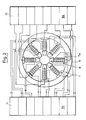
- FIGS. 2 and 3 A suitable corrector with the minimum number of poles is shown in FIGS. 2 and 3. It is an electrical and magnetic octopole for generating the four electrical and magnetic fields required for the correction. It is important that each of the multipoles electrically and magnetically discreet and can be set independently of all other poles. This greatly facilitates the setting during assembly.
- Each of the eight pole caps (8) and each of the eight coils (9) is supplied discretely by its own current (9b) or voltage generating device (8a).
- the poles are arranged in a circular manner at equal distances from one another in a sheathing ring (7).
- the pole shoes (7a) provide insulation from the sheathing ring (7).
- FIG. 4 shows a corrector arrangement which is suitable for both a scanning and a transmission electron microscope.
- a corrector arrangement according to FIG. 1 would also be suitable for a transmission electron microscope.
- the arrangement shown in FIG. 1 is suitable with an additional one electrical and magnetic quadrupole (6) only for a scanning electron microscope. If you wanted to use the arrangement in a transmission electron microscope, it would no longer be possible to center the quadrupole at the focal point of the image transmission lens (3) for reasons of space. Then, in the presence of the octupole, large off-axis errors occur, which make the arrangement unsuitable for installation in a transmission electron microscope. This problem is avoided with the arrangement according to FIG. 4.
- the arrangement of a corrector shown in Fig. 4 between an objective lens (12) and an image transmission lens (17) consists of two correctors (15, 18) of the type described in Fig. 1 and a "thick" telescopic round lens, which 4 is realized by two round lenses (13, 16) (round lens doublet). So that the two magnetic round lenses (13, 16) between the two correctors (15, 18) are free of rotation for the electrons, the current directions in the two round lenses (13, 16) must be opposite.
- the first corrector (15) is located in the intermediate image plane z5 behind the objective lens (12), ie on the object plane (14) opposite side of the objective lens (12).
- the course of the electron tracks in the interior of the corrector (15) corresponds to the courses from FIG. 1.
- Two round lenses (13, 16) now follow on the optical axis (19), between which there is an intermediate image plane Z e .
- the second corrector (18) now begins in the intermediate image plane Z7 after these two round lenses (13, 16) and ends at a further intermediate image plane Z8 in front of the image transmission lens (17).
- the chromatic error and the opening error of all round lenses of the system for all energies of the electrons can be corrected both in a scanning and in a transmission electron microscope.
- the correctors (15, 18), measured to the cathode, must be at a potential of approximately 5 to 10 KV.
- the potential on the object can be chosen as desired, depending on whether the objective lens (12) is operated as an acceleration or as a deceleration lens.
- the image transmission lens (17) can either be a magnetic lens or an electrical accelerating lens, depending on the energy that the electrons in the image plane should have.
- the dipole and quadrupole fields of the two correctors (15, 18) are the same large.
- the sextupol fields, on the other hand, are of different sizes and have opposite signs. Their value is first set in accordance with Appendix A and then optimized during the fine adjustment. This fine adjustment is necessary anyway, since the possible setting of the poles resulting from the calculated values according to the formulas in Appendix A is only sufficient for a rough adjustment (theoretical value determination with the formulas from Appendix A).
- the correction arrangement described in FIG. 4 can still be improved in that only one corrector of the Vienna type (20) is required. This allows easier operation, since only a corrector of the Vienna type (20) has to be raised and highly stabilized. This advantage is obtained by arranging the Vienna-type corrector (20) between two transfer lenses (21, 22).
- This corrector (20) begins in the image-side focal plane (z11) of the first transfer lens (21) and ends in the object-side focal plane (z12) of the second transfer lens (22). Both transfer lenses (21, 22) must have the same structure and excitation.
- the Vienna-type corrector (20) is excited in such a way that it does not produce 1st order chromatic astigmatism. This is achieved by fulfilling conditions 1) - 7) in Appendix A. Condition 8) for eliminating 3rd order spherical aberration can no longer be met if the potential of the object is to be arbitrary.
- the spherical aberration is corrected by two equally strong electrical or magnetic multipoles (23, 24), which are excited as hexapoles.
- the first of these multipoles (24) is centered on the object-side focal point (z10) of the first transfer lens (21).
- the second of these multipoles (23) is centered in the focal point (z13) of the second transfer lens (22).
- the transfer lenses (21, 22) are designed as weak round lenses. If the energy of the electrons in front of the first transfer lens (21) is not in the range of 5-10 keV, the transfer lenses (21, 22) must be electrical. If the energy is greater than 5-10 keV, then the first transfer lens (21) acts as a delay lens and the second transfer lens (22) as an accelerating lens. In this case, the Vienna-type corrector (20) lies within an intermediate retarder.
- first transfer lens (21) If the energy in front of the first transfer lens (21) is between 5 and 10 keV, then electrical or magnetic individual lenses can be used as transfer lenses (21, 22). Individual lenses are those lenses which have the same electrical potential on the object and image side. If magnetic transfer lenses are used, the current directions in the two lenses must be opposite.
- the geometry and the refractive powers of the two transfer lenses (21, 22) must be identical.
- the total corrector (25) thus consists of two identical hexapoles (23, 24), two identical transfer lenses (21, 22) and a corrector of the Vienna type (20).
- the overall corrector (25) is symmetrical with respect to its central plane (26) and to the optical axis (31).
- the great advantage of the overall corrector (25) described here is that only one element (20) has to be operated in a highly stable manner (in particular its dipole and quadrupole fields). In contrast, the stability of the hexapole fields only needs to be 1-2 orders of magnitude lower.
- a double objective lens (27) is required. This is given in FIG. 5 by the two lenses (28, 29).
- the use of such a double objective lens (27) on the object plane (30) has the advantage that its coma-free plane can be placed outside the field area of the lens (27). This is achieved by placing an intermediate image (z9) inside the double objective lens (27).
- the coma-free plane (z1 z) of the objective double lens (27) By placing the coma-free plane (z1 z) of the objective double lens (27) in the middle of the first multipole (24) operated as a hexapole and thus in the object-side focal plane (z10) of the first transfer lens (21), one achieves that no coma 3rd order occurs in the overall system. It is also achieved that this focal plane (z10) of the first transfer lens (21) is simultaneously a coma-free plane of the overall corrector (25) and the coma freedom of the objective double lens (27) is continuously guided to the overall corrector (25).
- the overall corrector (25) can thus also be referred to as an electron-optical aplanate.
- the intermediate image lies behind the total corrector (25) at infinity.
- the position of the intermediate image behind the overall corrector (25) can be adjusted as desired during operation without the geometry of the overall corrector (25) having to be changed. This setting may make it necessary to readjust the correction fields slightly.
Applications Claiming Priority (2)
| Application Number | Priority Date | Filing Date | Title |
|---|---|---|---|
| DE3841715 | 1988-12-10 | ||
| DE3841715A DE3841715A1 (de) | 1988-12-10 | 1988-12-10 | Abbildender korrektor vom wien-typ fuer elektronenmikroskope |
Publications (3)
| Publication Number | Publication Date |
|---|---|
| EP0373399A2 true EP0373399A2 (fr) | 1990-06-20 |
| EP0373399A3 EP0373399A3 (fr) | 1991-02-27 |
| EP0373399B1 EP0373399B1 (fr) | 1995-01-04 |
Family
ID=6368929
Family Applications (1)
| Application Number | Title | Priority Date | Filing Date |
|---|---|---|---|
| EP89121640A Expired - Lifetime EP0373399B1 (fr) | 1988-12-10 | 1989-11-23 | Système correcteur image du type de Wien pour microscopes électroniques |
Country Status (3)
| Country | Link |
|---|---|
| US (1) | US4962313A (fr) |
| EP (1) | EP0373399B1 (fr) |
| DE (2) | DE3841715A1 (fr) |
Cited By (11)
| Publication number | Priority date | Publication date | Assignee | Title |
|---|---|---|---|---|
| WO1997044811A1 (fr) * | 1996-05-21 | 1997-11-27 | Philips Electronics N.V. | Correcteur d'aberrations de lentilles d'appareils optiques a rayonnement corpusculaire |
| WO1998012732A1 (fr) * | 1996-09-20 | 1998-03-26 | Philips Electronics N.V. | Dispositif correcteur pour corriger les aberrations chromatiques dans un appareil optique a particules |
| WO1999033085A1 (fr) * | 1997-12-22 | 1999-07-01 | Philips Electron Optics B.V. | Dispositif de correction des aberrations chromatiques dans des appareils d'optique particulaire |
| WO1999038188A1 (fr) * | 1998-01-23 | 1999-07-29 | Ceos Corrected Electron Optical Systems Gmbh | Systeme de correction de l'aberration spherique de troisieme ordre d'une lentille, en particulier de l'objectif d'un microscope electronique |
| EP0989584A1 (fr) * | 1998-09-23 | 2000-03-29 | Advantest Corporation | Dispositif pour réduire la dispersion en énergie d'un faisceau de particules et appareil à faisceau de particules comportant un tel dispositif |
| WO2000036630A1 (fr) * | 1998-12-17 | 2000-06-22 | Philips Electron Optics B.V. | Appareil optique a particules impliquant une detection d'electrons d'auger |
| WO2005024889A1 (fr) * | 2003-09-11 | 2005-03-17 | ICT Integrated Circuit Testing Gesellschaft für Halbleiterprüftechnik mbH | Systeme de reduction de la largeur de l'energie d'un faisceau a particules chargees a etage simple pour systeme de faisceau a particules chargees |
| WO2005024890A1 (fr) * | 2003-09-11 | 2005-03-17 | ICT Integrated Circuit Testing Gesellschaft für Halbleiterprüftechnik mbH | Systeme de reduction de largeur d'energie de faisceau de particules chargees pour un systeme a faisceau de particules chargees |
| WO2005024888A2 (fr) * | 2003-09-11 | 2005-03-17 | ICT Integrated Circuit Testing Gesellschaft für Halbleiterprüftechnik mbH | Systeme de reduction de largeur d'energie de faisceau de particules chargees a deux etages pour un systeme a faisceau de particules chargees |
| JP2006253123A (ja) * | 2005-03-08 | 2006-09-21 | Ict Integrated Circuit Testing Ges Fuer Halbleiterprueftechnik Mbh | 高プローブ電流の撮像装置 |
| EP1783812A2 (fr) * | 2005-11-02 | 2007-05-09 | FEI Company | Correcteur pour la correction d'aberrations chromatiques dans un appareil optique à particules |
Families Citing this family (40)
| Publication number | Priority date | Publication date | Assignee | Title |
|---|---|---|---|---|
| EP0451370B1 (fr) * | 1990-04-12 | 1996-03-27 | Koninklijke Philips Electronics N.V. | Système correcteur pour un appareil à faisceau de particules chargées |
| NL9100294A (nl) * | 1991-02-20 | 1992-09-16 | Philips Nv | Geladen deeltjesbundelinrichting. |
| US5336891A (en) * | 1992-06-16 | 1994-08-09 | Arch Development Corporation | Aberration free lens system for electron microscope |
| JP3658034B2 (ja) * | 1995-02-28 | 2005-06-08 | キヤノン株式会社 | 画像観察光学系及び撮像光学系 |
| JP2001511303A (ja) | 1997-12-11 | 2001-08-07 | フィリップス エレクトロン オプティクス ビー ヴィ | 粒子−光学装置における球面収差補正用の補正デバイス |
| JP2000098293A (ja) | 1998-06-19 | 2000-04-07 | Canon Inc | 画像観察装置 |
| DE69939309D1 (de) * | 1999-03-31 | 2008-09-25 | Advantest Corp | Teilchenstrahlgerät zur schrägen Beobachtung einer Probe |
| US6614026B1 (en) * | 1999-04-15 | 2003-09-02 | Applied Materials, Inc. | Charged particle beam column |
| US6555818B1 (en) * | 1999-06-16 | 2003-04-29 | Jeol Ltd. | Transmission electron microscope |
| JP3757371B2 (ja) * | 1999-07-05 | 2006-03-22 | 日本電子株式会社 | エネルギーフィルタ及びそれを用いた電子顕微鏡 |
| US6410924B1 (en) * | 1999-11-16 | 2002-06-25 | Schlumberger Technologies, Inc. | Energy filtered focused ion beam column |
| US6836373B2 (en) | 2000-11-16 | 2004-12-28 | Jeol Ltd. | Spherical aberration corrector for electron microscope |
| US6593578B1 (en) * | 2001-11-08 | 2003-07-15 | Schlumberger Technologies, Inc. | Wien filter for use in a scanning electron microscope or the like |
| DE10159454B4 (de) * | 2001-12-04 | 2012-08-02 | Carl Zeiss Nts Gmbh | Korrektor zur Korrektion von Farbfehlern erster Ordnung, ersten Grades |
| DE10159308A1 (de) * | 2001-12-04 | 2003-06-12 | Ceos Gmbh | Teilchenoptischer Korrektor |
| JP4242101B2 (ja) * | 2002-02-08 | 2009-03-18 | 日本電子株式会社 | ウィーンフィルタ |
| US6924488B2 (en) * | 2002-06-28 | 2005-08-02 | Jeol Ltd. | Charged-particle beam apparatus equipped with aberration corrector |
| US6770887B2 (en) * | 2002-07-08 | 2004-08-03 | Ondrej L. Krivanek | Aberration-corrected charged-particle optical apparatus |
| JP4351108B2 (ja) * | 2004-04-07 | 2009-10-28 | 日本電子株式会社 | Semの収差自動補正方法及び収差自動補正装置 |
| JP2006216396A (ja) * | 2005-02-04 | 2006-08-17 | Hitachi High-Technologies Corp | 荷電粒子線装置 |
| TWI415162B (zh) * | 2005-03-03 | 2013-11-11 | Toshiba Kk | 映像投影型電子線裝置及使用該裝置之缺陷檢查系統 |
| KR20070116260A (ko) * | 2005-03-22 | 2007-12-07 | 가부시키가이샤 에바라 세이사꾸쇼 | 전자선장치 |
| DE602005023146D1 (de) * | 2005-07-11 | 2010-10-07 | Integrated Circuit Testing | Vorrichtung zur Erzeugung eines elektrisch-magnetischen Feldes und Aufbaumethode derselben |
| US8067732B2 (en) * | 2005-07-26 | 2011-11-29 | Ebara Corporation | Electron beam apparatus |
| US7394069B1 (en) | 2005-08-30 | 2008-07-01 | Kla-Tencor Technologies Corporation | Large-field scanning of charged particles |
| JP2007242490A (ja) * | 2006-03-10 | 2007-09-20 | Ebara Corp | 荷電粒子線光学系用の収差補正光学装置及び光学系 |
| JP2007335125A (ja) * | 2006-06-13 | 2007-12-27 | Ebara Corp | 電子線装置 |
| JP4881661B2 (ja) * | 2006-06-20 | 2012-02-22 | 株式会社日立ハイテクノロジーズ | 荷電粒子線装置 |
| JP4851268B2 (ja) * | 2006-08-31 | 2012-01-11 | 日本電子株式会社 | 収差補正方法および電子線装置 |
| EP1914785B1 (fr) * | 2006-10-20 | 2016-09-14 | JEOL Ltd. | Correcteur d'aberrations et procédé pour la correction d'aberrations |
| DE102007007923A1 (de) * | 2007-02-14 | 2008-08-21 | Carl Zeiss Nts Gmbh | Phasenschiebendes Element und Teilchenstrahlgerät mit phasenschiebenden Element |
| JP4533441B2 (ja) * | 2008-03-13 | 2010-09-01 | 株式会社日立製作所 | 荷電粒子装置の球面収差を補正する収差補正装置 |
| EP2166557A1 (fr) * | 2008-09-22 | 2010-03-24 | FEI Company | Procédé de correction de distorsions dans un appareil optique corpusculaire |
| DE102009052392A1 (de) * | 2009-11-09 | 2011-12-15 | Carl Zeiss Nts Gmbh | SACP-Verfahren und teilchenoptisches System zur Ausführung eines solchen Verfahrens |
| EP2325862A1 (fr) * | 2009-11-18 | 2011-05-25 | Fei Company | Correcteur pour aberrations axiales d'une lentille à particules chargées |
| DE102011009954A1 (de) * | 2011-02-01 | 2012-08-02 | Ceos Corrected Electron Optical Systems Gmbh | Korrektor |
| EP2511936B1 (fr) | 2011-04-13 | 2013-10-02 | Fei Company | Correction d'astigmatisme sans distorsion d'un TEM |
| JP5826529B2 (ja) | 2011-06-17 | 2015-12-02 | サンユー電子株式会社 | スピン回転装置 |
| US9275817B2 (en) * | 2012-04-09 | 2016-03-01 | Frederick Wight Martin | Particle-beam column corrected for both chromatic and spherical aberration |
| TWI506666B (zh) * | 2014-08-08 | 2015-11-01 | Nat Univ Tsing Hua | 桌上型電子顯微鏡及其複合多極-聚焦可調式磁透鏡 |
Citations (2)
| Publication number | Priority date | Publication date | Assignee | Title |
|---|---|---|---|---|
| US4389571A (en) * | 1981-04-01 | 1983-06-21 | The United States Of America As Represented By The United States Department Of Energy | Multiple sextupole system for the correction of third and higher order aberration |
| EP0231164A2 (fr) * | 1986-01-31 | 1987-08-05 | IMS Ionen Mikrofabrikations Systeme Gesellschaft m.b.H. | Dispositif pour appareils de projection ionique |
Family Cites Families (1)
| Publication number | Priority date | Publication date | Assignee | Title |
|---|---|---|---|---|
| US2919381A (en) * | 1956-07-25 | 1959-12-29 | Farrand Optical Co Inc | Electron lens |
-
1988
- 1988-12-10 DE DE3841715A patent/DE3841715A1/de not_active Withdrawn
-
1989
- 1989-11-23 EP EP89121640A patent/EP0373399B1/fr not_active Expired - Lifetime
- 1989-11-23 DE DE58908856T patent/DE58908856D1/de not_active Expired - Lifetime
- 1989-12-11 US US07/448,270 patent/US4962313A/en not_active Expired - Lifetime
Patent Citations (2)
| Publication number | Priority date | Publication date | Assignee | Title |
|---|---|---|---|---|
| US4389571A (en) * | 1981-04-01 | 1983-06-21 | The United States Of America As Represented By The United States Department Of Energy | Multiple sextupole system for the correction of third and higher order aberration |
| EP0231164A2 (fr) * | 1986-01-31 | 1987-08-05 | IMS Ionen Mikrofabrikations Systeme Gesellschaft m.b.H. | Dispositif pour appareils de projection ionique |
Non-Patent Citations (2)
| Title |
|---|
| NUCLEAR INSTRUMENTS AND METHODS. vol. 187, 1981, AMSTERDAM NL Seiten 187 - 199; H. Rose: "Correction of aperture aberrations in magnetic systems with threefold symmetry." * |
| OPTIK. vol. 77, no. 1, 1987, STUTTGART DE Seiten 26 - 34; H. Rose: "The retarding Wien filter as a high-performance imaging filter." * |
Cited By (24)
| Publication number | Priority date | Publication date | Assignee | Title |
|---|---|---|---|---|
| WO1997044811A1 (fr) * | 1996-05-21 | 1997-11-27 | Philips Electronics N.V. | Correcteur d'aberrations de lentilles d'appareils optiques a rayonnement corpusculaire |
| WO1998012732A1 (fr) * | 1996-09-20 | 1998-03-26 | Philips Electronics N.V. | Dispositif correcteur pour corriger les aberrations chromatiques dans un appareil optique a particules |
| WO1999033085A1 (fr) * | 1997-12-22 | 1999-07-01 | Philips Electron Optics B.V. | Dispositif de correction des aberrations chromatiques dans des appareils d'optique particulaire |
| WO1999038188A1 (fr) * | 1998-01-23 | 1999-07-29 | Ceos Corrected Electron Optical Systems Gmbh | Systeme de correction de l'aberration spherique de troisieme ordre d'une lentille, en particulier de l'objectif d'un microscope electronique |
| EP0989584A1 (fr) * | 1998-09-23 | 2000-03-29 | Advantest Corporation | Dispositif pour réduire la dispersion en énergie d'un faisceau de particules et appareil à faisceau de particules comportant un tel dispositif |
| WO2000036630A1 (fr) * | 1998-12-17 | 2000-06-22 | Philips Electron Optics B.V. | Appareil optique a particules impliquant une detection d'electrons d'auger |
| EP1521289A1 (fr) * | 2003-09-11 | 2005-04-06 | ICT Integrated Circuit Testing Gesellschaft für Halbleiterprüftechnik mbH | Système à un seul étage pour réduire la dispersion en énergie d'un faisceau de particules chargées pour un système à faisceau de particules chargées |
| US7507956B2 (en) | 2003-09-11 | 2009-03-24 | ICT Integrated Circuit Testing Gesellschaft für Halbleiterprüftechnik mbH | Charged particle beam energy width reduction system for charged particle beam system |
| WO2005024888A2 (fr) * | 2003-09-11 | 2005-03-17 | ICT Integrated Circuit Testing Gesellschaft für Halbleiterprüftechnik mbH | Systeme de reduction de largeur d'energie de faisceau de particules chargees a deux etages pour un systeme a faisceau de particules chargees |
| EP1517353A2 (fr) * | 2003-09-11 | 2005-03-23 | ICT Integrated Circuit Testing Gesellschaft für Halbleiterprüftechnik mbH | Système pour reduire la dispersion en énergie d'un faisceau de particules chargées pour un système à faisceau de particules chargées |
| EP1517354A2 (fr) * | 2003-09-11 | 2005-03-23 | ICT Integrated Circuit Testing Gesellschaft für Halbleiterprüftechnik mbH | System à deux étages pour reduire la dispersion en énergie d'un faisceau de particules chargées pour un système à faisceau de particules chargées |
| EP1517353A3 (fr) * | 2003-09-11 | 2005-03-30 | ICT Integrated Circuit Testing Gesellschaft für Halbleiterprüftechnik mbH | Système pour reduire la dispersion en énergie d'un faisceau de particules chargées pour un système à faisceau de particules chargées |
| WO2005024889A1 (fr) * | 2003-09-11 | 2005-03-17 | ICT Integrated Circuit Testing Gesellschaft für Halbleiterprüftechnik mbH | Systeme de reduction de la largeur de l'energie d'un faisceau a particules chargees a etage simple pour systeme de faisceau a particules chargees |
| EP1517354A3 (fr) * | 2003-09-11 | 2005-04-13 | ICT Integrated Circuit Testing Gesellschaft für Halbleiterprüftechnik mbH | System à deux étages pour reduire la dispersion en énergie d'un faisceau de particules chargées pour un système à faisceau de particules chargées |
| WO2005024888A3 (fr) * | 2003-09-11 | 2005-04-28 | Integrated Circuit Testing | Systeme de reduction de largeur d'energie de faisceau de particules chargees a deux etages pour un systeme a faisceau de particules chargees |
| WO2005024890A1 (fr) * | 2003-09-11 | 2005-03-17 | ICT Integrated Circuit Testing Gesellschaft für Halbleiterprüftechnik mbH | Systeme de reduction de largeur d'energie de faisceau de particules chargees pour un systeme a faisceau de particules chargees |
| US7679054B2 (en) | 2003-09-11 | 2010-03-16 | ICT Integrated Circuit Testing Gesellschaft für Halbleiterprüftechnik mbH | Double stage charged particle beam energy width reduction system for charged particle beam system |
| JP2006253123A (ja) * | 2005-03-08 | 2006-09-21 | Ict Integrated Circuit Testing Ges Fuer Halbleiterprueftechnik Mbh | 高プローブ電流の撮像装置 |
| US7361897B2 (en) | 2005-03-08 | 2008-04-22 | Ict Integrated Circuit Testing Gesellschaft Fur Halbleiterpruftechnik Mbh | Imaging apparatus for high probe currents |
| EP1739714A1 (fr) | 2005-03-08 | 2007-01-03 | ICT Integrated Circuit Testing Gesellschaft für Halbleiterprüftechnik mbH | Système d'imagerie pour courants élevés |
| EP1783811A2 (fr) * | 2005-11-02 | 2007-05-09 | FEI Company | Correcteur pour la correction d'aberrations chromatiques dans un appareil optique à particules |
| EP1783811A3 (fr) * | 2005-11-02 | 2008-02-27 | FEI Company | Correcteur pour la correction d'aberrations chromatiques dans un appareil optique à particules |
| EP1783812A3 (fr) * | 2005-11-02 | 2008-03-05 | FEI Company | Correcteur pour la correction d'aberrations chromatiques dans un appareil optique à particules |
| EP1783812A2 (fr) * | 2005-11-02 | 2007-05-09 | FEI Company | Correcteur pour la correction d'aberrations chromatiques dans un appareil optique à particules |
Also Published As
| Publication number | Publication date |
|---|---|
| US4962313A (en) | 1990-10-09 |
| DE3841715A1 (de) | 1990-06-13 |
| EP0373399A3 (fr) | 1991-02-27 |
| EP0373399B1 (fr) | 1995-01-04 |
| DE58908856D1 (de) | 1995-02-16 |
Similar Documents
| Publication | Publication Date | Title |
|---|---|---|
| EP0373399B1 (fr) | Système correcteur image du type de Wien pour microscopes électroniques | |
| EP1220292B1 (fr) | Monochromateur pour particules chargées | |
| EP0530640B1 (fr) | Système de formation d'images de faisceau de particules chargées avec miroir correcteur | |
| EP0617451B1 (fr) | Filtre en énergie d'électrons, produisant une image | |
| DE112014003890B4 (de) | Mit einem Strahl geladener Teilchen arbeitende Vorrichtung | |
| DE69733408T2 (de) | Korrigiervorrichtung zur korrektur chromatischer fehler in einem partikel-optischen gerät | |
| EP1057204B1 (fr) | Systeme de correction de l'aberration spherique de troisieme ordre d'une lentille, en particulier de l'objectif d'un microscope electronique | |
| EP1277221B1 (fr) | Canon electronique pour electrons ou faisceaux ioniques de haute monochromie ou de haute densite de courant | |
| EP2068344B1 (fr) | Correcteur optique à particules pour trajectoire de faisceau axiale et hors axe | |
| DE69822802T2 (de) | Korrigiervorrichtung zur behebung des chromatischen fehlers in korpuskularoptischen geräten | |
| EP2008294B1 (fr) | Correcteur optoélectronique pour systèmes de représentation aplanétiques | |
| DE112015001235B4 (de) | Vorrichtung und verfahren zur abbildung mittels eines elektronenstrahls unter verwendung eines monochromators mit doppeltem wien-filter sowie monochromator | |
| EP2051279B1 (fr) | Correcteur | |
| DE3933317A1 (de) | Saeule zur erzeugung eines fokussierten ionenstrahls | |
| DE112015002818T5 (de) | Vorrichtung zur Erzeugung eines Strahls geladener Teilchen und Aberrationskorrektor | |
| EP1386342A2 (fr) | Systeme de deviation pour un appareil a faisceau de particules | |
| EP1451847B1 (fr) | Correcteur en optique des particules | |
| DE2608958A1 (de) | Vorrichtung zum erzeugen von strahlen aus geladenen teilchen | |
| DE10217507B4 (de) | Anordnung zur Abbildung des von einer Probe gepulst emittierten Teilchenensembles auf einem Detektor | |
| EP3780064A1 (fr) | Correcteur optique à particules sans erreurs axiales de sixième ordre et microscope électronique pourvu d'un correcteur | |
| EP1190433B1 (fr) | Correcteur electrostatique permettant de supprimer les aberrations chromatiques de lentilles a particules | |
| WO2004042770A2 (fr) | Filtre d'energie generateur d'images pour particules chargees electriquement et utilisation de ce filtre | |
| EP2224464A1 (fr) | Système optique corpusculaire de formation d'image (variantes) | |
| EP0086431A2 (fr) | Système générateur de faisceau de particules et méthode d'utilisation | |
| EP2466613B1 (fr) | Correcteur |
Legal Events
| Date | Code | Title | Description |
|---|---|---|---|
| PUAI | Public reference made under article 153(3) epc to a published international application that has entered the european phase |
Free format text: ORIGINAL CODE: 0009012 |
|
| AK | Designated contracting states |
Kind code of ref document: A2 Designated state(s): DE FR GB IT NL |
|
| PUAL | Search report despatched |
Free format text: ORIGINAL CODE: 0009013 |
|
| AK | Designated contracting states |
Kind code of ref document: A3 Designated state(s): DE FR GB IT NL |
|
| 17P | Request for examination filed |
Effective date: 19910730 |
|
| 17Q | First examination report despatched |
Effective date: 19930903 |
|
| GRAA | (expected) grant |
Free format text: ORIGINAL CODE: 0009210 |
|
| AK | Designated contracting states |
Kind code of ref document: B1 Designated state(s): DE FR GB IT NL |
|
| PG25 | Lapsed in a contracting state [announced via postgrant information from national office to epo] |
Ref country code: IT Free format text: LAPSE BECAUSE OF FAILURE TO SUBMIT A TRANSLATION OF THE DESCRIPTION OR TO PAY THE FEE WITHIN THE PRE;WARNING: LAPSES OF ITALIAN PATENTS WITH EFFECTIVE DATE BEFORE 2007 MAY HAVE OCCURRED AT ANY TIME BEFORE 2007. THE CORRECT EFFECTIVE DATE MAY BE DIFFERENT FROM THE ONE RECORDED.SCRIBED TIME-LIMIT Effective date: 19950104 Ref country code: FR Effective date: 19950104 |
|
| REF | Corresponds to: |
Ref document number: 58908856 Country of ref document: DE Date of ref document: 19950216 |
|
| GBT | Gb: translation of ep patent filed (gb section 77(6)(a)/1977) |
Effective date: 19950315 |
|
| EN | Fr: translation not filed | ||
| PLBE | No opposition filed within time limit |
Free format text: ORIGINAL CODE: 0009261 |
|
| STAA | Information on the status of an ep patent application or granted ep patent |
Free format text: STATUS: NO OPPOSITION FILED WITHIN TIME LIMIT |
|
| 26N | No opposition filed | ||
| REG | Reference to a national code |
Ref country code: GB Ref legal event code: IF02 |
|
| REG | Reference to a national code |
Ref country code: GB Ref legal event code: 732E |
|
| NLS | Nl: assignments of ep-patents |
Owner name: CARL ZEISS SMT AG |
|
| PGFP | Annual fee paid to national office [announced via postgrant information from national office to epo] |
Ref country code: NL Payment date: 20081113 Year of fee payment: 20 Ref country code: DE Payment date: 20081121 Year of fee payment: 20 |
|
| PGFP | Annual fee paid to national office [announced via postgrant information from national office to epo] |
Ref country code: GB Payment date: 20081117 Year of fee payment: 20 |
|
| REG | Reference to a national code |
Ref country code: GB Ref legal event code: PE20 Expiry date: 20091122 |
|
| NLV7 | Nl: ceased due to reaching the maximum lifetime of a patent |
Effective date: 20091123 |
|
| PG25 | Lapsed in a contracting state [announced via postgrant information from national office to epo] |
Ref country code: NL Free format text: LAPSE BECAUSE OF EXPIRATION OF PROTECTION Effective date: 20091123 |
|
| PG25 | Lapsed in a contracting state [announced via postgrant information from national office to epo] |
Ref country code: GB Free format text: LAPSE BECAUSE OF EXPIRATION OF PROTECTION Effective date: 20091122 |