EP0371834A1 - Verfahren und Vorrichtung zum Befestigen von Teilen an Kolbenköpfen hydraulischer Pumpen durch Magnetimpulsformen - Google Patents
Verfahren und Vorrichtung zum Befestigen von Teilen an Kolbenköpfen hydraulischer Pumpen durch Magnetimpulsformen Download PDFInfo
- Publication number
- EP0371834A1 EP0371834A1 EP89402982A EP89402982A EP0371834A1 EP 0371834 A1 EP0371834 A1 EP 0371834A1 EP 89402982 A EP89402982 A EP 89402982A EP 89402982 A EP89402982 A EP 89402982A EP 0371834 A1 EP0371834 A1 EP 0371834A1
- Authority
- EP
- European Patent Office
- Prior art keywords
- crimping
- piston
- shoe
- head
- propellant
- Prior art date
- Legal status (The legal status is an assumption and is not a legal conclusion. Google has not performed a legal analysis and makes no representation as to the accuracy of the status listed.)
- Granted
Links
Images


Classifications
-
- F—MECHANICAL ENGINEERING; LIGHTING; HEATING; WEAPONS; BLASTING
- F16—ENGINEERING ELEMENTS AND UNITS; GENERAL MEASURES FOR PRODUCING AND MAINTAINING EFFECTIVE FUNCTIONING OF MACHINES OR INSTALLATIONS; THERMAL INSULATION IN GENERAL
- F16C—SHAFTS; FLEXIBLE SHAFTS; ELEMENTS OR CRANKSHAFT MECHANISMS; ROTARY BODIES OTHER THAN GEARING ELEMENTS; BEARINGS
- F16C32/00—Bearings not otherwise provided for
- F16C32/06—Bearings not otherwise provided for with moving member supported by a fluid cushion formed, at least to a large extent, otherwise than by movement of the shaft, e.g. hydrostatic air-cushion bearings
- F16C32/0662—Details of hydrostatic bearings independent of fluid supply or direction of load
- F16C32/0666—Details of hydrostatic bearings independent of fluid supply or direction of load of bearing pads
-
- B—PERFORMING OPERATIONS; TRANSPORTING
- B21—MECHANICAL METAL-WORKING WITHOUT ESSENTIALLY REMOVING MATERIAL; PUNCHING METAL
- B21D—WORKING OR PROCESSING OF SHEET METAL OR METAL TUBES, RODS OR PROFILES WITHOUT ESSENTIALLY REMOVING MATERIAL; PUNCHING METAL
- B21D26/00—Shaping without cutting otherwise than using rigid devices or tools or yieldable or resilient pads, i.e. applying fluid pressure or magnetic forces
- B21D26/14—Shaping without cutting otherwise than using rigid devices or tools or yieldable or resilient pads, i.e. applying fluid pressure or magnetic forces applying magnetic forces
-
- B—PERFORMING OPERATIONS; TRANSPORTING
- B23—MACHINE TOOLS; METAL-WORKING NOT OTHERWISE PROVIDED FOR
- B23P—METAL-WORKING NOT OTHERWISE PROVIDED FOR; COMBINED OPERATIONS; UNIVERSAL MACHINE TOOLS
- B23P15/00—Making specific metal objects by operations not covered by a single other subclass or a group in this subclass
- B23P15/003—Making specific metal objects by operations not covered by a single other subclass or a group in this subclass bearings
-
- F—MECHANICAL ENGINEERING; LIGHTING; HEATING; WEAPONS; BLASTING
- F16—ENGINEERING ELEMENTS AND UNITS; GENERAL MEASURES FOR PRODUCING AND MAINTAINING EFFECTIVE FUNCTIONING OF MACHINES OR INSTALLATIONS; THERMAL INSULATION IN GENERAL
- F16C—SHAFTS; FLEXIBLE SHAFTS; ELEMENTS OR CRANKSHAFT MECHANISMS; ROTARY BODIES OTHER THAN GEARING ELEMENTS; BEARINGS
- F16C11/00—Pivots; Pivotal connections
- F16C11/04—Pivotal connections
- F16C11/06—Ball-joints; Other joints having more than one degree of angular freedom, i.e. universal joints
- F16C11/0619—Ball-joints; Other joints having more than one degree of angular freedom, i.e. universal joints the female part comprising a blind socket receiving the male part
Definitions
- the present invention relates to a crimping process by magnetoforming of a shoe on a spherical piston head for a hydraulic pump as well as a device for the implementation of this process.
- magnetoforming or electromagnetic forming consists in principle, in forming materials, without mechanical contact, by electromagnetic field forces.
- the capacitors of a generator are discharged into the turns of a coil surrounding a tubular part to be formed or housed inside it. This discharge produces in the workpiece, for a very short time, intense induced currents, oscillating and highly damped.
- the voltages used can be between 3000 and 15000 volts, the energies dissipated in the coil can reach approximately 48 K. Joules, their duration being of the order of 100 micro-seconds, which corresponds to an instantaneous power which can reach approximately 480 Mega Watts.
- shots thus carried out can be executed either with an explosive reel, which is used only once and is destroyed after use, or with a permanent reel, held in place by a suitable support and which allows serial operations.
- the object of the invention is to apply the magnetoforming technique to crimping pads. on spherical heads of pistons for hydraulic pumps.
- the crimping of the pads on the spherical heads of these pistons has been carried out by mechanical contact, (mainly flow forming) supplemented by the use of abrasive.
- the two parts must be crimped with a play and a the lowest possible swiveling torque, to guarantee optimum pump performance.
- the piston head is first coated with an abrasive film or the latter is injected with oil after crimping.
- the difficulty is therefore to obtain a very good swiveling with extremely low operating torque and play, in particular a practically zero axial play.
- the crimping must be extremely hard, so that it is then difficult to recreate the necessary clearance.
- this method has the drawback of generating spherical bearing defects in the skid due to the technique of pushing back and to the presence of interposition product causing too limited spans, while giving an initial "feeling" of axial play. and correct swiveling. But therefore the pad wears out quickly and it follows that the pump takes up play very quickly (for example 1/10 mm of axial play) and that its efficiency decreases.
- the object of the invention is to use magnetoforming to crimp the pads on the spherical heads of pistons, in order to benefit from the advantages of this process over mechanical crimping.
- advantages are, in particular, the absence of influence of the geometric tolerances "of interfaces" of the shoe on the crimping, the absence of tool wear and constraints in the non-affected areas, the ultra-rapid crimping (gross duration less than 1 ms) allowing mass production with very short times, and the simultaneous creation of the required swiveling clearance without subsequent shaping operation.
- a soluble organic film intended to reserve a swiveling clearance is interposed between the head of the piston and the shoe, then after crimping, this film is destroyed by dissolution in a suitable solvent.
- a soluble film of the hair spray type (polymer resin in solution such as a carboxylic terpolymer in solution in ethanol at 93%), and as methanol or ethanol solvent.
- the piston is heated before crimping to a predetermined temperature, then its head is introduced into the shoe, and after crimping the piston head is allowed to cool in order to create a set of swiveling between it and the shoe.
- the crimping device for implementing the second embodiment of the above method comprises a crimping station provided with a pad holder and a magnetic induction coil supplied by a generator, means for heating the piston prior to its introduction into the pad, and means for moving the piston after heating to the pad.
- the heating means can be an oven or a temperature-controlled heat transfer fluid system, and the device can also comprise a tube for transferring the successive pistons after heating at the crimping station, as well as a piston for driving the pistons in the tube.
- the device shown in Fig.1 comprises a station 1 for crimping a shoe 2 on the spherical head 3 of the cylindrical body 4 of a piston 5 intended for a hydraulic pump such as that of Fig.7.
- Station 1 comprises an inductor assembly 10 which comprises, on the one hand, two annular inductor coils 7, of axis XX connected in series, each provided with a flat coil 6 securely embedded in a very rigid carcass, and on the other share a field concentrator 17.
- the latter consists of a plate interposed between the coils 7, pierced with a central opening for passage of a shoe 2, and on each side of which the two coils 7 are securely fixed.
- the shoe 2 is carried by a support 8, and the coils 7 are powered by a generator 9.
- the latter, the support 8 and the concentrator 17 can be produced in a manner known per se, the concentrator being able for example to consist of a copper-beryllium alloy.
- the device also comprises means for heating the piston 5 before its introduction into the shoe 2.
- these means consist of a thermostatically controlled oven 11 for heating the piston 5.
- This oven 11 is connected to the crimping 1 by a tube 12 for transferring the successive pistons 5 after heating at station 1.
- a jack 13 preferably pneumatic, the rod 14 of which can penetrate into the furnace 11 to convey the preheated pistons 5 into the tube 12 until their spherical heads 3 are introduced inside the corresponding pads 2 and applied with a thrust of approximately 50 daN during the crimping phase.
- the inductor assembly 10, the tube 12 and the jack 13 are arranged along the general horizontal axis X-X, the device being supported by uprights 15 on a base 16.
- the pad support 8 is equipped with means for extracting from the rear (along arrow F) pistons 5 provided with pads 2 crimped.
- the support 8 contains an electrical box (known per se and not shown) for controlling sequences of the generator 9 and supplying the furnace 11. This box contains a temperature indicator and a safety system indicating that the piston 5 is in place in the shoe 2 and authorizing the automatic "firing" of the generator 9 in the coils 7, with a time delay for example of approximately 0.1 seconds.
- the crimping station 1 also includes a ring 18 called a "propellant", made of a very good electrically conductive material such as pure copper.
- This ring 18 is dimensioned to be able to grip and overflow the end of the pad 2 oriented towards the body 4 of the piston 5, and interposed between the latter and the field concentrator 17.
- an insulating ring 19 is interposed between the propellant 18 and a projecting peripheral collar 2a formed at the end of the shoe 2, which has the function of suitably positioning the propellant 18.
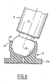
- irregularities are formed on the outer surface of the pad 2 enclosed by the propellant 18. These irregularities may preferably be constituted by an annular notch 21 limited on the side of the body 4 of the piston 5 by a terminal projection 22 (Fig.6).
- the spherical head 3 is generally made of a suitable steel (for example 100 c6 treated steel), the temperature of this head 3 must never reach 180 ° C., even superficially.
- the oven 11 is therefore adjusted accordingly, and so that at the time of crimping, after transfer of the heated piston 5 by the tube 12, the temperature difference between the piston 2 and the head 3 is of the order of 100 ° C approximately (depending on the desired game).
- imperative temperature constraint indicated above excludes heating processes that can reach this limit even briefly, without possible control, for example radiation, induction ...
- the oven 11 provides indirect heating of the pads 2 by heat transfer fluid, the regulated temperature of which is strictly less than 180 ° C.
- the fluid used is chosen so that it does not cause corrosion of the parts, the latter being made of non-stainless steel.
- the pad is put in place with its centering support 8 in the inductor 10 opposite the outlet of the tube 12. Then, by means of the jack 13, a hot piston 5 is transferred from the distributor oven 11 in the tube 12 towards the shoe 2.
- the spherical head 3 of the piston 5 is applied, without shock, in the sphere of the pad 2 with a thrust of about 50 daN.
- the crimping "shot” is then carried out automatically by discharging the general tor 9 in the coils 7.
- the thrust can be increased without inconvenience, 50daN being a minimum for correct maintenance of the parts.
- the electrical power discharged into the coils 7 is approximately 50 to 100% greater than the theoretical power required for crimping.
- An extremely enveloping crimping is thus obtained, at the same time as the very reduced clearance desired between the head 3 and the shoe 2, this very slight clearance allowing itself a very low swiveling torque.
- the part of the shoe 2 enclosed by the propellant 18 is crimped tightly on the spherical head 3, and the propellant 18 comes to marry the notch 21 and the projection 22.
- the propellant 18 and the ring 19 are extracted from the shoe 2 by means of an appropriate tool, not shown, specific to each type of crimped assembly and distinct from the crimping device.
- the crimping zone does not have any defect (such as crack or crack) and the clearance as well as the corresponding swiveling torque extremely reduced, are therefore obtained in a single operation, without any subsequent recovery of the swiveling clearance being necessary.
- the energy sent into the coils 7 by the generator 9 can be 1.3 K. Joules for a spherical head 3 whose diameter is between approximately 4.77 and 4.79 mm.
- the axial play obtained is less than or equal to 0.01 mm and the corresponding swiveling torque is less than or equal to 0.003 mN.
- the spherical heads 3 are covered before crimping with an appropriate film-lacquer as mentioned above.
- the oven 11 of the device in Fig.1 is not heated.
- the execution of the crimp is similar to that described in the context of the preceding thermal process, with this difference and that according to which, after crimping and removal of the propellant 18 and the ring 19, the film is dissolved with a solvent such as those already indicated.
- the device shown in Fig.3 and 4 includes a crimping station 1A in which the crimping is carried out with a coil 7A called "lost" or explosive. These terms are used in opposition to the so-called “permanent” coils 7, thanks to their robust construction with the coils 6 embedded in a solid carcass, and to the addition of the concentrator 17.
- the coil 7A supplied by the generator 9, is no longer embedded in a support, but simply consists of a cylindrical winding of varnished copper wire which is used only once. It can be arranged as it is around the propellant 18, and is destroyed during crimping.
- the winding of the coil 7A can be glued to a sleeve 30 of cardboard or plastic (Fig.4A) for example, or else molded in a plastic material 31 (Fig.4B).
- This variant has the advantage of a simple and rapid construction for crimping in small quantities, the drawback being the consumption of a coil by crimping.
- the implementation of the crimping remains similar to that of one of the preceding embodiments, depending on the choice of the swiveling clearance by thermal effect or by depositing film-lacquer on the heads of the pistons 5.
- FIG.5 A third embodiment of the invention called “manual” is shown in Fig.5. This variant does not use the thermal effect (heating of the piston) to obtain the clearance, but only the soluble film technique.
- the coil 6A is connected to the generator 9 to perform the crimping shot.
- Fig.7 shows a hydraulic pump 20 equipped with a series of pistons 5 arranged coaxially with its general axis YY and to which the invention can be applied.
- This pump 20 is of a type known per se and will therefore not be described in detail. It will only be indicated that the pads 2, crimped onto the heads 3 of the pistons 5, are in sliding contact on a surface 25 inclined at an appropriate angle on the axis YY.
Applications Claiming Priority (2)
| Application Number | Priority Date | Filing Date | Title |
|---|---|---|---|
| FR8815598 | 1988-11-29 | ||
| FR8815598A FR2639560B1 (fr) | 1988-11-29 | 1988-11-29 | Procede et dispositif pour le sertissage par magnetoformage de patins sur des tetes de pistons de pompes hydrauliques |
Publications (2)
| Publication Number | Publication Date |
|---|---|
| EP0371834A1 true EP0371834A1 (de) | 1990-06-06 |
| EP0371834B1 EP0371834B1 (de) | 1995-03-29 |
Family
ID=9372377
Family Applications (1)
| Application Number | Title | Priority Date | Filing Date |
|---|---|---|---|
| EP19890402982 Expired - Lifetime EP0371834B1 (de) | 1988-11-29 | 1989-10-27 | Verfahren und Vorrichtung zum Befestigen von Teilen an Kolbenköpfen hydraulischer Pumpen durch Magnetimpulsformen |
Country Status (4)
| Country | Link |
|---|---|
| EP (1) | EP0371834B1 (de) |
| DE (1) | DE68921963T2 (de) |
| ES (1) | ES2071673T3 (de) |
| FR (1) | FR2639560B1 (de) |
Cited By (5)
| Publication number | Priority date | Publication date | Assignee | Title |
|---|---|---|---|---|
| WO1998007894A1 (en) * | 1996-08-23 | 1998-02-26 | Alliedsignal Inc. | Method for making parts usable in a fuel environment |
| WO1998042949A1 (de) * | 1997-03-26 | 1998-10-01 | Brueninghaus Hydromatik Gmbh | Verfahren zum herstellen einer kugelgelenkverbindung |
| WO2001007785A2 (de) * | 1999-07-21 | 2001-02-01 | Brueninghaus Hydromatik Gmbh | Kugelgelenkverbindung zwischen einem gleitschuh und einem kolben |
| EP1225349A2 (de) | 2001-01-23 | 2002-07-24 | Brueninghaus Hydromatik Gmbh | Fügeverfahren für eine Kugelgelenkverbindung |
| WO2019186083A1 (fr) * | 2018-03-30 | 2019-10-03 | Gaztransport Et Technigaz | Pré-assemblage de pièces |
Families Citing this family (1)
| Publication number | Priority date | Publication date | Assignee | Title |
|---|---|---|---|---|
| JP5975531B2 (ja) * | 2011-03-31 | 2016-08-23 | 武蔵精密工業株式会社 | ボールジョイントの製造方法 |
Citations (4)
| Publication number | Priority date | Publication date | Assignee | Title |
|---|---|---|---|---|
| US2904874A (en) * | 1956-11-20 | 1959-09-22 | Thompson Ramo Wooldridge Inc | Method of manufacturing connecting rod bearings |
| US3191264A (en) * | 1962-03-26 | 1965-06-29 | Borg Warner | Method of making a piston and piston rod assembly |
| FR1435694A (fr) * | 1964-06-11 | 1966-04-15 | Gen Dynamics Corp | Procédé d'emmanchement par retrait et appareil pour sa mise en oeuvre |
| FR1492589A (fr) * | 1965-09-14 | 1967-08-18 | Siemens Ag | Procédé de fabrication d'une liaison tournante entre au moins deux pièces symétriques par rapport à un axe de rotation au point de liaison |
-
1988
- 1988-11-29 FR FR8815598A patent/FR2639560B1/fr not_active Expired - Lifetime
-
1989
- 1989-10-27 ES ES89402982T patent/ES2071673T3/es not_active Expired - Lifetime
- 1989-10-27 EP EP19890402982 patent/EP0371834B1/de not_active Expired - Lifetime
- 1989-10-27 DE DE1989621963 patent/DE68921963T2/de not_active Expired - Lifetime
Patent Citations (4)
| Publication number | Priority date | Publication date | Assignee | Title |
|---|---|---|---|---|
| US2904874A (en) * | 1956-11-20 | 1959-09-22 | Thompson Ramo Wooldridge Inc | Method of manufacturing connecting rod bearings |
| US3191264A (en) * | 1962-03-26 | 1965-06-29 | Borg Warner | Method of making a piston and piston rod assembly |
| FR1435694A (fr) * | 1964-06-11 | 1966-04-15 | Gen Dynamics Corp | Procédé d'emmanchement par retrait et appareil pour sa mise en oeuvre |
| FR1492589A (fr) * | 1965-09-14 | 1967-08-18 | Siemens Ag | Procédé de fabrication d'une liaison tournante entre au moins deux pièces symétriques par rapport à un axe de rotation au point de liaison |
Non-Patent Citations (1)
| Title |
|---|
| MAGNEFORM, THE ELECTROMAGNETIC METALFORMING MACHINE, 1963, General Dynamics, General Atomic Division, San Diego, California, US * |
Cited By (14)
| Publication number | Priority date | Publication date | Assignee | Title |
|---|---|---|---|---|
| WO1998007894A1 (en) * | 1996-08-23 | 1998-02-26 | Alliedsignal Inc. | Method for making parts usable in a fuel environment |
| US6343888B1 (en) | 1997-03-26 | 2002-02-05 | Brueninghaus Hydromatik Gmbh | Method for the production of a ball jointed connection |
| WO1998042949A1 (de) * | 1997-03-26 | 1998-10-01 | Brueninghaus Hydromatik Gmbh | Verfahren zum herstellen einer kugelgelenkverbindung |
| US6840696B1 (en) | 1999-07-21 | 2005-01-11 | Brueninghaus Hydromatik Gmbh | Method for producing a ball-and-socket joint between a slipper and a piston, and a ball-and-socket joint of this type |
| WO2001007785A3 (de) * | 1999-07-21 | 2002-11-14 | Brueninghaus Hydromatik Gmbh | Kugelgelenkverbindung zwischen einem gleitschuh und einem kolben |
| WO2001007785A2 (de) * | 1999-07-21 | 2001-02-01 | Brueninghaus Hydromatik Gmbh | Kugelgelenkverbindung zwischen einem gleitschuh und einem kolben |
| EP1225349A2 (de) | 2001-01-23 | 2002-07-24 | Brueninghaus Hydromatik Gmbh | Fügeverfahren für eine Kugelgelenkverbindung |
| DE10102989A1 (de) * | 2001-01-23 | 2002-08-01 | Brueninghaus Hydromatik Gmbh | Fügeverfahren für eine Kugelgelenkverbindung |
| EP1225349A3 (de) * | 2001-01-23 | 2002-11-13 | Brueninghaus Hydromatik Gmbh | Fügeverfahren für eine Kugelgelenkverbindung |
| DE10102989C2 (de) * | 2001-01-23 | 2002-11-21 | Brueninghaus Hydromatik Gmbh | Fügeverfahren für eine Kugelgelenkverbindung |
| WO2019186083A1 (fr) * | 2018-03-30 | 2019-10-03 | Gaztransport Et Technigaz | Pré-assemblage de pièces |
| FR3079436A1 (fr) * | 2018-03-30 | 2019-10-04 | Gaztransport Et Technigaz | Pre-assemblage de pieces |
| CN112135712A (zh) * | 2018-03-30 | 2020-12-25 | 气体运输技术公司 | 部件的预组装件 |
| CN112135712B (zh) * | 2018-03-30 | 2023-08-04 | 气体运输技术公司 | 部件的预组装件 |
Also Published As
| Publication number | Publication date |
|---|---|
| EP0371834B1 (de) | 1995-03-29 |
| FR2639560A1 (fr) | 1990-06-01 |
| ES2071673T3 (es) | 1995-07-01 |
| DE68921963T2 (de) | 1995-11-23 |
| FR2639560B1 (fr) | 1994-04-08 |
| DE68921963D1 (de) | 1995-05-04 |
Similar Documents
| Publication | Publication Date | Title |
|---|---|---|
| EP0445035B1 (de) | Verfahren zum Reibschweissen | |
| EP0279732B1 (de) | Panzerbrechendes Geschoss mit hartem Kern und dehnbarer Buchse und Verfahren zu dessen Herstellung | |
| EP0371834B1 (de) | Verfahren und Vorrichtung zum Befestigen von Teilen an Kolbenköpfen hydraulischer Pumpen durch Magnetimpulsformen | |
| EP1864365A1 (de) | Elektrische drehmaschine mit einem zwischen dem schaft und den polarrädern angeordneten zwischenmantel und verfahren zur herstellung des rotors | |
| FR2658378A1 (fr) | Chalumeau a plasma rotatif. | |
| EP0408405B1 (de) | Vorrichtung zum Laserschweissen im Inneren eines Rohrelementes | |
| FR2659688A1 (fr) | Aube pour moteur a turbine a gaz. | |
| BE1014736A5 (fr) | Procede de fabrication et de recharge de cibles pour pulverisation cathodique. | |
| EP0808680A1 (de) | Maschine zum Pressen oder Giessen unter Druck | |
| FR2651835A1 (fr) | Propulseur a reaction assiste par un arc electrique. | |
| EP0779525A1 (de) | Vorrichtung für die Einkopplung eines Leistungslaserstrahls in eine optische Faser | |
| FR2842801A1 (fr) | Procede pour le moulage fin sous pression de composants optiques | |
| EP0867253A1 (de) | Verfahren und Anlage zum Be- und Entladen von Elektroden einer Punktschweisszange bei einem Widerstandspunktschweissgerät | |
| EP0490756B1 (de) | Verfahren zur Herstellung eines aus einem bei Umgebungstemperatur nicht-schmiedbaren Material bestehenden Teiles, und entsprechendes Werkzeug | |
| FR2560971A1 (fr) | Bougie a incandescence pour moteurs diesel de vehicules automobiles | |
| FR2539660A1 (fr) | Procede et dispositif pour le decoupage d'un fil | |
| EP2896818A1 (de) | Axiale Abschaltvorrichtung auf einer Welle, und Anlasser, der eine solche Vorrichtung umfasst | |
| EP0034528B1 (de) | Spanndorne | |
| EP0329529A1 (de) | Verfahren zum Verbinden von Kunststoff-Teilen unter Verwendung eines Vernetzungsmittels und einer elektrischen Widerstandsheizung | |
| EP0246954B1 (de) | Rotierender Hydraulikverteiler und Zusammenstellungsverfahren für solchen Verteiler | |
| EP0193425B1 (de) | Verfahren zur Befestigung eines dünnwandigen Rohres zwischen einem konischen Ring und einer konischen Innenhülse und Vorrichtung zur Durchführung des Verfahrens | |
| EP0041430A1 (de) | Verfahren und Anordnung zum fortwährenden Löten, ausgehend von an zusätzliche Heizung unterliegenden Lötungen mittels Drähten | |
| FR2856472A1 (fr) | Dispositif de corps propulsif d'un projectile pour un canon a rails | |
| FR2485412A1 (fr) | Rouleau tubulaire pour machines de coulee continue | |
| FR3102385A1 (fr) | Dispositif pour l’expansion a froid d’un perçage debouchant |
Legal Events
| Date | Code | Title | Description |
|---|---|---|---|
| PUAI | Public reference made under article 153(3) epc to a published international application that has entered the european phase |
Free format text: ORIGINAL CODE: 0009012 |
|
| AK | Designated contracting states |
Kind code of ref document: A1 Designated state(s): DE ES GB IT |
|
| 17P | Request for examination filed |
Effective date: 19901130 |
|
| 17Q | First examination report despatched |
Effective date: 19920521 |
|
| GRAA | (expected) grant |
Free format text: ORIGINAL CODE: 0009210 |
|
| AK | Designated contracting states |
Kind code of ref document: B1 Designated state(s): DE ES GB IT |
|
| ITF | It: translation for a ep patent filed |
Owner name: JACOBACCI & PERANI S.P.A. |
|
| REF | Corresponds to: |
Ref document number: 68921963 Country of ref document: DE Date of ref document: 19950504 |
|
| REG | Reference to a national code |
Ref country code: ES Ref legal event code: FG2A Ref document number: 2071673 Country of ref document: ES Kind code of ref document: T3 |
|
| GBT | Gb: translation of ep patent filed (gb section 77(6)(a)/1977) |
Effective date: 19950707 |
|
| PLBE | No opposition filed within time limit |
Free format text: ORIGINAL CODE: 0009261 |
|
| STAA | Information on the status of an ep patent application or granted ep patent |
Free format text: STATUS: NO OPPOSITION FILED WITHIN TIME LIMIT |
|
| 26N | No opposition filed | ||
| REG | Reference to a national code |
Ref country code: GB Ref legal event code: IF02 |
|
| PGFP | Annual fee paid to national office [announced via postgrant information from national office to epo] |
Ref country code: DE Payment date: 20081027 Year of fee payment: 20 |
|
| PGFP | Annual fee paid to national office [announced via postgrant information from national office to epo] |
Ref country code: ES Payment date: 20081121 Year of fee payment: 20 |
|
| PGFP | Annual fee paid to national office [announced via postgrant information from national office to epo] |
Ref country code: IT Payment date: 20081028 Year of fee payment: 20 |
|
| PGFP | Annual fee paid to national office [announced via postgrant information from national office to epo] |
Ref country code: GB Payment date: 20081022 Year of fee payment: 20 |
|
| REG | Reference to a national code |
Ref country code: GB Ref legal event code: PE20 Expiry date: 20091026 |
|
| REG | Reference to a national code |
Ref country code: ES Ref legal event code: FD2A Effective date: 20091028 |
|
| PG25 | Lapsed in a contracting state [announced via postgrant information from national office to epo] |
Ref country code: ES Free format text: LAPSE BECAUSE OF EXPIRATION OF PROTECTION Effective date: 20091028 |
|
| PG25 | Lapsed in a contracting state [announced via postgrant information from national office to epo] |
Ref country code: GB Free format text: LAPSE BECAUSE OF EXPIRATION OF PROTECTION Effective date: 20091026 |