EP0371834A1 - Method and device for fastening sliding parts onto piston heads of hydraulic pumps by electromagnetic shaping - Google Patents
Method and device for fastening sliding parts onto piston heads of hydraulic pumps by electromagnetic shaping Download PDFInfo
- Publication number
- EP0371834A1 EP0371834A1 EP89402982A EP89402982A EP0371834A1 EP 0371834 A1 EP0371834 A1 EP 0371834A1 EP 89402982 A EP89402982 A EP 89402982A EP 89402982 A EP89402982 A EP 89402982A EP 0371834 A1 EP0371834 A1 EP 0371834A1
- Authority
- EP
- European Patent Office
- Prior art keywords
- crimping
- piston
- shoe
- head
- propellant
- Prior art date
- Legal status (The legal status is an assumption and is not a legal conclusion. Google has not performed a legal analysis and makes no representation as to the accuracy of the status listed.)
- Granted
Links
Images


Classifications
-
- F—MECHANICAL ENGINEERING; LIGHTING; HEATING; WEAPONS; BLASTING
- F16—ENGINEERING ELEMENTS AND UNITS; GENERAL MEASURES FOR PRODUCING AND MAINTAINING EFFECTIVE FUNCTIONING OF MACHINES OR INSTALLATIONS; THERMAL INSULATION IN GENERAL
- F16C—SHAFTS; FLEXIBLE SHAFTS; ELEMENTS OR CRANKSHAFT MECHANISMS; ROTARY BODIES OTHER THAN GEARING ELEMENTS; BEARINGS
- F16C32/00—Bearings not otherwise provided for
- F16C32/06—Bearings not otherwise provided for with moving member supported by a fluid cushion formed, at least to a large extent, otherwise than by movement of the shaft, e.g. hydrostatic air-cushion bearings
- F16C32/0662—Details of hydrostatic bearings independent of fluid supply or direction of load
- F16C32/0666—Details of hydrostatic bearings independent of fluid supply or direction of load of bearing pads
-
- B—PERFORMING OPERATIONS; TRANSPORTING
- B21—MECHANICAL METAL-WORKING WITHOUT ESSENTIALLY REMOVING MATERIAL; PUNCHING METAL
- B21D—WORKING OR PROCESSING OF SHEET METAL OR METAL TUBES, RODS OR PROFILES WITHOUT ESSENTIALLY REMOVING MATERIAL; PUNCHING METAL
- B21D26/00—Shaping without cutting otherwise than using rigid devices or tools or yieldable or resilient pads, i.e. applying fluid pressure or magnetic forces
- B21D26/14—Shaping without cutting otherwise than using rigid devices or tools or yieldable or resilient pads, i.e. applying fluid pressure or magnetic forces applying magnetic forces
-
- B—PERFORMING OPERATIONS; TRANSPORTING
- B23—MACHINE TOOLS; METAL-WORKING NOT OTHERWISE PROVIDED FOR
- B23P—METAL-WORKING NOT OTHERWISE PROVIDED FOR; COMBINED OPERATIONS; UNIVERSAL MACHINE TOOLS
- B23P15/00—Making specific metal objects by operations not covered by a single other subclass or a group in this subclass
- B23P15/003—Making specific metal objects by operations not covered by a single other subclass or a group in this subclass bearings
-
- F—MECHANICAL ENGINEERING; LIGHTING; HEATING; WEAPONS; BLASTING
- F16—ENGINEERING ELEMENTS AND UNITS; GENERAL MEASURES FOR PRODUCING AND MAINTAINING EFFECTIVE FUNCTIONING OF MACHINES OR INSTALLATIONS; THERMAL INSULATION IN GENERAL
- F16C—SHAFTS; FLEXIBLE SHAFTS; ELEMENTS OR CRANKSHAFT MECHANISMS; ROTARY BODIES OTHER THAN GEARING ELEMENTS; BEARINGS
- F16C11/00—Pivots; Pivotal connections
- F16C11/04—Pivotal connections
- F16C11/06—Ball-joints; Other joints having more than one degree of angular freedom, i.e. universal joints
- F16C11/0619—Ball-joints; Other joints having more than one degree of angular freedom, i.e. universal joints the female part comprising a blind socket receiving the male part
Definitions
- the present invention relates to a crimping process by magnetoforming of a shoe on a spherical piston head for a hydraulic pump as well as a device for the implementation of this process.
- magnetoforming or electromagnetic forming consists in principle, in forming materials, without mechanical contact, by electromagnetic field forces.
- the capacitors of a generator are discharged into the turns of a coil surrounding a tubular part to be formed or housed inside it. This discharge produces in the workpiece, for a very short time, intense induced currents, oscillating and highly damped.
- the voltages used can be between 3000 and 15000 volts, the energies dissipated in the coil can reach approximately 48 K. Joules, their duration being of the order of 100 micro-seconds, which corresponds to an instantaneous power which can reach approximately 480 Mega Watts.
- shots thus carried out can be executed either with an explosive reel, which is used only once and is destroyed after use, or with a permanent reel, held in place by a suitable support and which allows serial operations.
- the object of the invention is to apply the magnetoforming technique to crimping pads. on spherical heads of pistons for hydraulic pumps.
- the crimping of the pads on the spherical heads of these pistons has been carried out by mechanical contact, (mainly flow forming) supplemented by the use of abrasive.
- the two parts must be crimped with a play and a the lowest possible swiveling torque, to guarantee optimum pump performance.
- the piston head is first coated with an abrasive film or the latter is injected with oil after crimping.
- the difficulty is therefore to obtain a very good swiveling with extremely low operating torque and play, in particular a practically zero axial play.
- the crimping must be extremely hard, so that it is then difficult to recreate the necessary clearance.
- this method has the drawback of generating spherical bearing defects in the skid due to the technique of pushing back and to the presence of interposition product causing too limited spans, while giving an initial "feeling" of axial play. and correct swiveling. But therefore the pad wears out quickly and it follows that the pump takes up play very quickly (for example 1/10 mm of axial play) and that its efficiency decreases.
- the object of the invention is to use magnetoforming to crimp the pads on the spherical heads of pistons, in order to benefit from the advantages of this process over mechanical crimping.
- advantages are, in particular, the absence of influence of the geometric tolerances "of interfaces" of the shoe on the crimping, the absence of tool wear and constraints in the non-affected areas, the ultra-rapid crimping (gross duration less than 1 ms) allowing mass production with very short times, and the simultaneous creation of the required swiveling clearance without subsequent shaping operation.
- a soluble organic film intended to reserve a swiveling clearance is interposed between the head of the piston and the shoe, then after crimping, this film is destroyed by dissolution in a suitable solvent.
- a soluble film of the hair spray type (polymer resin in solution such as a carboxylic terpolymer in solution in ethanol at 93%), and as methanol or ethanol solvent.
- the piston is heated before crimping to a predetermined temperature, then its head is introduced into the shoe, and after crimping the piston head is allowed to cool in order to create a set of swiveling between it and the shoe.
- the crimping device for implementing the second embodiment of the above method comprises a crimping station provided with a pad holder and a magnetic induction coil supplied by a generator, means for heating the piston prior to its introduction into the pad, and means for moving the piston after heating to the pad.
- the heating means can be an oven or a temperature-controlled heat transfer fluid system, and the device can also comprise a tube for transferring the successive pistons after heating at the crimping station, as well as a piston for driving the pistons in the tube.
- the device shown in Fig.1 comprises a station 1 for crimping a shoe 2 on the spherical head 3 of the cylindrical body 4 of a piston 5 intended for a hydraulic pump such as that of Fig.7.
- Station 1 comprises an inductor assembly 10 which comprises, on the one hand, two annular inductor coils 7, of axis XX connected in series, each provided with a flat coil 6 securely embedded in a very rigid carcass, and on the other share a field concentrator 17.
- the latter consists of a plate interposed between the coils 7, pierced with a central opening for passage of a shoe 2, and on each side of which the two coils 7 are securely fixed.
- the shoe 2 is carried by a support 8, and the coils 7 are powered by a generator 9.
- the latter, the support 8 and the concentrator 17 can be produced in a manner known per se, the concentrator being able for example to consist of a copper-beryllium alloy.
- the device also comprises means for heating the piston 5 before its introduction into the shoe 2.
- these means consist of a thermostatically controlled oven 11 for heating the piston 5.
- This oven 11 is connected to the crimping 1 by a tube 12 for transferring the successive pistons 5 after heating at station 1.
- a jack 13 preferably pneumatic, the rod 14 of which can penetrate into the furnace 11 to convey the preheated pistons 5 into the tube 12 until their spherical heads 3 are introduced inside the corresponding pads 2 and applied with a thrust of approximately 50 daN during the crimping phase.
- the inductor assembly 10, the tube 12 and the jack 13 are arranged along the general horizontal axis X-X, the device being supported by uprights 15 on a base 16.
- the pad support 8 is equipped with means for extracting from the rear (along arrow F) pistons 5 provided with pads 2 crimped.
- the support 8 contains an electrical box (known per se and not shown) for controlling sequences of the generator 9 and supplying the furnace 11. This box contains a temperature indicator and a safety system indicating that the piston 5 is in place in the shoe 2 and authorizing the automatic "firing" of the generator 9 in the coils 7, with a time delay for example of approximately 0.1 seconds.
- the crimping station 1 also includes a ring 18 called a "propellant", made of a very good electrically conductive material such as pure copper.
- This ring 18 is dimensioned to be able to grip and overflow the end of the pad 2 oriented towards the body 4 of the piston 5, and interposed between the latter and the field concentrator 17.
- an insulating ring 19 is interposed between the propellant 18 and a projecting peripheral collar 2a formed at the end of the shoe 2, which has the function of suitably positioning the propellant 18.
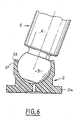
- irregularities are formed on the outer surface of the pad 2 enclosed by the propellant 18. These irregularities may preferably be constituted by an annular notch 21 limited on the side of the body 4 of the piston 5 by a terminal projection 22 (Fig.6).
- the spherical head 3 is generally made of a suitable steel (for example 100 c6 treated steel), the temperature of this head 3 must never reach 180 ° C., even superficially.
- the oven 11 is therefore adjusted accordingly, and so that at the time of crimping, after transfer of the heated piston 5 by the tube 12, the temperature difference between the piston 2 and the head 3 is of the order of 100 ° C approximately (depending on the desired game).
- imperative temperature constraint indicated above excludes heating processes that can reach this limit even briefly, without possible control, for example radiation, induction ...
- the oven 11 provides indirect heating of the pads 2 by heat transfer fluid, the regulated temperature of which is strictly less than 180 ° C.
- the fluid used is chosen so that it does not cause corrosion of the parts, the latter being made of non-stainless steel.
- the pad is put in place with its centering support 8 in the inductor 10 opposite the outlet of the tube 12. Then, by means of the jack 13, a hot piston 5 is transferred from the distributor oven 11 in the tube 12 towards the shoe 2.
- the spherical head 3 of the piston 5 is applied, without shock, in the sphere of the pad 2 with a thrust of about 50 daN.
- the crimping "shot” is then carried out automatically by discharging the general tor 9 in the coils 7.
- the thrust can be increased without inconvenience, 50daN being a minimum for correct maintenance of the parts.
- the electrical power discharged into the coils 7 is approximately 50 to 100% greater than the theoretical power required for crimping.
- An extremely enveloping crimping is thus obtained, at the same time as the very reduced clearance desired between the head 3 and the shoe 2, this very slight clearance allowing itself a very low swiveling torque.
- the part of the shoe 2 enclosed by the propellant 18 is crimped tightly on the spherical head 3, and the propellant 18 comes to marry the notch 21 and the projection 22.
- the propellant 18 and the ring 19 are extracted from the shoe 2 by means of an appropriate tool, not shown, specific to each type of crimped assembly and distinct from the crimping device.
- the crimping zone does not have any defect (such as crack or crack) and the clearance as well as the corresponding swiveling torque extremely reduced, are therefore obtained in a single operation, without any subsequent recovery of the swiveling clearance being necessary.
- the energy sent into the coils 7 by the generator 9 can be 1.3 K. Joules for a spherical head 3 whose diameter is between approximately 4.77 and 4.79 mm.
- the axial play obtained is less than or equal to 0.01 mm and the corresponding swiveling torque is less than or equal to 0.003 mN.
- the spherical heads 3 are covered before crimping with an appropriate film-lacquer as mentioned above.
- the oven 11 of the device in Fig.1 is not heated.
- the execution of the crimp is similar to that described in the context of the preceding thermal process, with this difference and that according to which, after crimping and removal of the propellant 18 and the ring 19, the film is dissolved with a solvent such as those already indicated.
- the device shown in Fig.3 and 4 includes a crimping station 1A in which the crimping is carried out with a coil 7A called "lost" or explosive. These terms are used in opposition to the so-called “permanent” coils 7, thanks to their robust construction with the coils 6 embedded in a solid carcass, and to the addition of the concentrator 17.
- the coil 7A supplied by the generator 9, is no longer embedded in a support, but simply consists of a cylindrical winding of varnished copper wire which is used only once. It can be arranged as it is around the propellant 18, and is destroyed during crimping.
- the winding of the coil 7A can be glued to a sleeve 30 of cardboard or plastic (Fig.4A) for example, or else molded in a plastic material 31 (Fig.4B).
- This variant has the advantage of a simple and rapid construction for crimping in small quantities, the drawback being the consumption of a coil by crimping.
- the implementation of the crimping remains similar to that of one of the preceding embodiments, depending on the choice of the swiveling clearance by thermal effect or by depositing film-lacquer on the heads of the pistons 5.
- FIG.5 A third embodiment of the invention called “manual” is shown in Fig.5. This variant does not use the thermal effect (heating of the piston) to obtain the clearance, but only the soluble film technique.
- the coil 6A is connected to the generator 9 to perform the crimping shot.
- Fig.7 shows a hydraulic pump 20 equipped with a series of pistons 5 arranged coaxially with its general axis YY and to which the invention can be applied.
- This pump 20 is of a type known per se and will therefore not be described in detail. It will only be indicated that the pads 2, crimped onto the heads 3 of the pistons 5, are in sliding contact on a surface 25 inclined at an appropriate angle on the axis YY.
Abstract
Description
La présente invention a pour objet un procédé de sertissage par magnétoformage d'un patin sur une tête sphérique de piston pour pompe hydraulique ainsi qu'un dispositif pour la mise en oeuvre de ce procédé.The present invention relates to a crimping process by magnetoforming of a shoe on a spherical piston head for a hydraulic pump as well as a device for the implementation of this process.
On sait que le magnétoformage ou formage électromagnétique consiste dans son principe, à former des matériaux, sans contact mécanique, par des forces de champs électromagnétiques. A cet effet, on décharge les condensateurs d'un générateur dans les spires d'une bobine entourant une pièce tubulaire à former ou logée à l'intérieur de celle-ci. Cette décharge produit dans la pièce à former, pendant un temps très bref, des courants induits intenses, oscillants et fortement amortis.It is known that magnetoforming or electromagnetic forming consists in principle, in forming materials, without mechanical contact, by electromagnetic field forces. To this end, the capacitors of a generator are discharged into the turns of a coil surrounding a tubular part to be formed or housed inside it. This discharge produces in the workpiece, for a very short time, intense induced currents, oscillating and highly damped.
Ces courants de Foucault créent avec le champ magnétique produit par le courant parcourant la bobine des forces de répulsion très élevées entre la bobine et la pièce, laquelle est ainsi repoussée et formée au profil voulu.These eddy currents create, with the magnetic field produced by the current flowing through the coil, very high repulsion forces between the coil and the part, which is thus repelled and formed to the desired profile.
Les tensions utilisées peuvent se situer entre 3000 et 15000 Volts, les énergies dissipées dans la bobine peuvent atteindre environ 48 K.Joules, leur durée étant de l'ordre de 100 micro-seconde, ce qui correspond à une puissance instantanée pouvant atteindre environ 480 Méga-Watts.The voltages used can be between 3000 and 15000 volts, the energies dissipated in the coil can reach approximately 48 K. Joules, their duration being of the order of 100 micro-seconds, which corresponds to an instantaneous power which can reach approximately 480 Mega Watts.
Les "tirs" ainsi effectués peuvent être exécutés soit avec une bobine explosive, qui ne sert qu'une seule fois et est détruite après usage, soit avec une bobine permanente, maintenue en place par un support convenable et qui permet des opérations en série.The "shots" thus carried out can be executed either with an explosive reel, which is used only once and is destroyed after use, or with a permanent reel, held in place by a suitable support and which allows serial operations.
L'invention a pour but d'appliquer la technique de magnétoformage au sertissage de patins sur des têtes sphériques de pistons pour pompes hydrauliques. Habituellement jusqu'à présent, le sertissage des patins sur les têtes sphériques de ces pistons a été effectué par contact mécanique, (principalement fluotournage) complété par l'utilisation d'abrasif En effet, les deux pièces doivent être serties avec un jeu et un couple de rotulage les plus réduits possibles, afin de garantir à la pompe un rendement optimum. La tête du piston est au préalable enduite d'un film d'abrasif ou bien ce dernier est injecté avec de l'huile après sertissage.The object of the invention is to apply the magnetoforming technique to crimping pads. on spherical heads of pistons for hydraulic pumps. Usually until now, the crimping of the pads on the spherical heads of these pistons has been carried out by mechanical contact, (mainly flow forming) supplemented by the use of abrasive. Indeed, the two parts must be crimped with a play and a the lowest possible swiveling torque, to guarantee optimum pump performance. The piston head is first coated with an abrasive film or the latter is injected with oil after crimping.
La difficulté est donc d'obtenir un rotulage de très bonne qualité avec un couple de fonctionnement et un jeu extrêmement faibles, en particulier un jeu axial pratiquement nul. Or, pour sertir le patin à la forme parfaitement sphérique de la tête du piston, le sertissage doit être extrêmement dur, de sorte qu'ensuite il est difficile de recréer le jeu nécessaire. En particulier ce procédé a l'inconvénient de générer dans le patin des défauts de portée sphérique dûs à la technique de repoussage et à la présence de produit d'interposition provoquant des portées trop restreintes, tout en donnant une "sensation" initiale de jeu axial et de rotulage corrects. Mais de ce fait le patin s'use rapidement et il en résulte que la pompe prend très rapidement du jeu (par exemple 1/10 mm de jeu axial) et que son rendement diminue.The difficulty is therefore to obtain a very good swiveling with extremely low operating torque and play, in particular a practically zero axial play. However, to crimp the shoe to the perfectly spherical shape of the piston head, the crimping must be extremely hard, so that it is then difficult to recreate the necessary clearance. In particular, this method has the drawback of generating spherical bearing defects in the skid due to the technique of pushing back and to the presence of interposition product causing too limited spans, while giving an initial "feeling" of axial play. and correct swiveling. But therefore the pad wears out quickly and it follows that the pump takes up play very quickly (for example 1/10 mm of axial play) and that its efficiency decreases.
L'invention a pour but d'utiliser le magnétoformage pour sertir les patins sur les têtes sphériques de pistons, afin de bénéficier des avantages de ce procédé sur le sertissage mécanique. Ces avantages sont, notamment, l'absence d'influence des tolérances géométriques "d'interfaces" du patin sur le sertissage, l'absence d'usure d'outillage et de contraintes dans les zones non concernées, l'ultra rapidité du sertissage (durée brute inférieure à 1ms) permettant la production en série avec des temps très courts, et la création simultanée du jeu de rotulage requis sans opération ultérieure de conformage.The object of the invention is to use magnetoforming to crimp the pads on the spherical heads of pistons, in order to benefit from the advantages of this process over mechanical crimping. These advantages are, in particular, the absence of influence of the geometric tolerances "of interfaces" of the shoe on the crimping, the absence of tool wear and constraints in the non-affected areas, the ultra-rapid crimping (gross duration less than 1 ms) allowing mass production with very short times, and the simultaneous creation of the required swiveling clearance without subsequent shaping operation.
Selon un premier mode de réalisation du procédé visé par l'invention, on interpose avant sertissage, entre la tête du piston et le patin, un film organique soluble destiné à réserver un jeu de rotulage, puis après sertissage on détruit ce film par dissolution dans un solvant approprié.According to a first embodiment of the process referred to by the invention, before crimping, a soluble organic film intended to reserve a swiveling clearance is interposed between the head of the piston and the shoe, then after crimping, this film is destroyed by dissolution in a suitable solvent.
A titre indicatif on peut utiliser par exemple un film soluble du type laque pour cheveux (résine polymère en solution telle qu'un terpolymère carboxylique en solution dans de l'éthanol à 93%), et comme solvant du méthanol ou de l'éthanol.As an indication, it is possible to use, for example, a soluble film of the hair spray type (polymer resin in solution such as a carboxylic terpolymer in solution in ethanol at 93%), and as methanol or ethanol solvent.
Selon un second mode de réalisation du procédé conforme à l'invention, on chauffe avant sertissage le piston à une température prédéterminée, puis on introduit sa tête dans le patin, et après sertissage on laisse refroidir la tête du piston afin de créer un jeu de rotulage entre celle-ci et le patin.According to a second embodiment of the method according to the invention, the piston is heated before crimping to a predetermined temperature, then its head is introduced into the shoe, and after crimping the piston head is allowed to cool in order to create a set of swiveling between it and the shoe.
Ainsi est obtenu le jeu souhaité par effet thermique différentiel entre la tête du piston et le patin.Thus the desired clearance is obtained by differential thermal effect between the head of the piston and the shoe.
Le dispositif de sertissage pour la mise en oeuvre du second mode de réalisation du procédé ci-dessus comprend un poste de sertissage pourvu d'un support de patins et d'une bobine d'induction magnétique alimentée par un générateur, des moyens de chauffage du piston préalablement à son introduction dans le patin, et des moyens pour déplacer le piston après chauffage jusqu'au patin.The crimping device for implementing the second embodiment of the above method comprises a crimping station provided with a pad holder and a magnetic induction coil supplied by a generator, means for heating the piston prior to its introduction into the pad, and means for moving the piston after heating to the pad.
Les moyens de chauffage peuvent être un four ou un système à fluide caloporteur de température régulée, et le dispositif peut en outre comporter un tube de transfert des pistons successifs après chauffage au poste de sertissage, ainsi qu'un vérin d'entraînement des pistons dans le tube.The heating means can be an oven or a temperature-controlled heat transfer fluid system, and the device can also comprise a tube for transferring the successive pistons after heating at the crimping station, as well as a piston for driving the pistons in the tube.
D'autres particularités et avantages de l'invention apparaitront au cours de la description qui va suivre, faite en référence aux dessins annexés qui en illustrent une forme de réalisation à titre d'exemple non limitatif.
- La figure 1 est une vue en élévation longitudinale schématique d'une première forme de réalisation du dispositif de sertissage selon l'invention.
- La figure 2 est une vue en élévation simplifiée à échelle agrandie du poste de sertissage du dispositif de la Fig.1.
- La figure 3 est une vue analogue à la Fig.1 d'une seconde forme de réalisation du dispositif selon l'invention.
- La figure 4 est une vue analogue à la Fig.2 du poste de sertissage du dispositif de la Fig.3.
- Les figures 4A et 4B sont des vues de détail de variantes d'exécution de l'ensemble inducteur de la Fig.4.
- La figure 5 est une vue analogue à la Fig.4 montrant une variante du sertissage.
- La figure 6 est une vue mi-coupe transversale, mi-élévation avec arrachement d'un piston de pompe hydraulique sur la tête duquel a été serti un patin conformément à l'invention.
- La figure 7 est une vue en coupe axiale d'une pompe hydraulique aux pistons de laquelle l'invention est applicable.
- Figure 1 is a schematic longitudinal elevational view of a first embodiment of the crimping device according to the invention.
- Figure 2 is a simplified elevational view on an enlarged scale of the crimping station of the device of Fig.1.
- Figure 3 is a view similar to Fig.1 of a second embodiment of the device according to the invention.
- Figure 4 is a view similar to Fig.2 of the crimping station of the device of Fig.3.
- Figures 4A and 4B are detailed views of alternative embodiments of the inductor assembly of Fig.4.
- Figure 5 is a view similar to Fig.4 showing a variant of the crimping.
- Figure 6 is a half cross-sectional, mid-elevation view with cutaway of a hydraulic pump piston on the head of which has been crimped a shoe according to the invention.
- Figure 7 is an axial sectional view of a hydraulic piston pump to which the invention is applicable.
Le dispositif représenté à la Fig.1 comprend un poste 1 de sertissage d'un patin 2 sur la tête sphérique 3 du corps cylindrique 4 d'un piston 5 destiné à une pompe hydraulique telle que celle de la Fig.7.The device shown in Fig.1 comprises a station 1 for crimping a
Le poste 1 comprend un ensemble inducteur 10 qui comporte, d'une part, deux bobines inductrices annulaires 7, d'axe XX reliées en série, pourvues chacun d'un bobinage plan 6 solidement noyé dans une carcasse très rigide, et d'autre part un concentreur de champ 17. Ce dernier est constitué d'une plaque intercalée entre les bobines 7, percé d'une ouverture centrale de passage d'un patin 2, et sur chaque côté de laquelle les deux bobines 7 sont solidement fixées.Station 1 comprises an
Le patin 2 est porté par un support 8, et les bobines 7 sont alimentées par un générateur 9. Ce dernier, le support 8 et le concentreur 17 peuvent être réalisés de manière connue en soi, le concentreur pouvant par exemple être constitué d'un alliage cuivre-béryllium.The
Le dispositif comprend également des moyens de chauffage du piston 5 avant son introduction dans le patin 2. Dans l'exemple décrit, ces moyens sont constitués par un four 11 thermostaté de mise en chauffe du piston 5. Ce four 11 est relié au poste de sertissage 1 par un tube 12 de transfert des pistons successifs 5 après chauffage au poste 1. Ces transferts peuvent être assurés par un vérin 13, de préférence pneumatique, dont la tige 14 peut pénétrer dans le four 11 pour acheminer les pistons préchauffés 5 dans le tube 12 jusqu'à ce que leurs têtes sphériques 3 viennent s'introduire à l'intérieur des patins correspondants 2 et s'appliquer avec une poussée d'environ 50 daN pendant la phase sertissage.The device also comprises means for heating the
L'ensemble inducteur 10, le tube 12 et le vérin 13 sont disposés suivant l'axe général X-X horizontal, le dispositif étant en appui par des montants 15 sur une base 16.The
Le support de patins 8 est équipé de moyens d'extraction par l'arrière (suivant la flèche F) des pistons 5 munis de patins 2 sertis. Le support 8 contient un coffret électrique (connu en soi et non représenté) de commande de séquences du générateur 9 et d'alimentation du four 11. Ce coffret contient un indicateur de température et un système de sécurité indiquant que le piston 5 est en place dans le patin 2 et autorisant le "tir" automatique du générateur 9 dans les bobines 7, avec une temporisation par exemple de 0,1 seconde environ.The
Le poste de sertissage 1 comprend également une bague 18 appelée "propulseur", en un matériau conducteur électrique très bon tel que le cuivre pur. Cette bague 18 est dimensionnée pour pouvoir enserrer et déborder l'extrémité du patin 2 orientée vers le corps 4 du piston 5, et interposée entre celui-ci et le concentreur de champ 17. De plus, entre le propulseur 18 et un collet périphérique saillant 2a formé à l'extrémité du patin 2, est interposée une bague isolante 19 qui a pour fonction de positionner convenablement le propulseur 18.The crimping station 1 also includes a
Par ailleurs, afin que lors du "tir" du générateur 9 dans les bobines 7, le propulseur 18 ne risque pas de glisser sur le patin 2, des irrégularités sont ménagées sur la surface extérieure du patin 2 enserrée par le propulseur 18. Ces irrégularités peuvent être de préférence constituées par une encoche annulaire 21 limitée du côté du corps 4 du piston 5 par un ressaut terminal 22 (Fig.6).Furthermore, so that during the "firing" of the generator 9 in the
La mise en oeuvre du dispositif de sertissage qui vient d'être décrit, par le procédé conforme à l'invention, est la suivante.The implementation of the crimping device which has just been described, by the method according to the invention, is as follows.
Compte tenu que la tête sphérique 3 est généralement constituée en un acier approprié (par exemple de l'acier 100 c6 traité), la température de cette tête 3 ne doit jamais atteindre 180°C, même superficiellement. Le four 11 est donc réglé en conséquence, et de telle sorte qu'au moment du sertissage, après transfert du piston chauffé 5 par le tube 12, la différence de température entre le piston 2 et la tête 3 soit de l'ordre de 100°C environ (suivant le jeu souhaité).Given that the
Incidemment, la contrainte impérative de température indiquée ci-dessus exclut les procédés de chauffage pouvant atteindre cette limite même brièvement, sans contrôle possible, par exemple rayonnement, induction ...Incidentally, the imperative temperature constraint indicated above excludes heating processes that can reach this limit even briefly, without possible control, for example radiation, induction ...
De préférence le four 11 assure le chauffage indirect des patins 2 par fluide caloporteur, dont la température régulée est strictement inférieure à 180°C. Le fluide utilisé est choisi de manière qu'il n'entraîne pas de corrosion des pièces, ces dernières étant en acier non inoxydable.Preferably the
On met en place tout d'abord le patin avec son support de centrage 8 dans l'inducteur 10 en face de la sortie du tube 12. Ensuite on réalise, au moyen du vérin 13, le transfert d'un piston chaud 5 depuis le four distributeur 11 dans le tube 12 vers le patin 2.First of all, the pad is put in place with its centering
La tête sphérique 3 du piston 5 vient s'appliquer, sans choc, dans la sphère du patin 2 avec une poussée d'environ 50 daN. Le "tir" de sertissage s'effectue alors automatiquement par décharge du généra teur 9 dans les bobines 7. La poussée peut être augmentée sans inconvénient, 50daN étant un minimum pour un maintien correct des pièces.The
Selon une particularité du procédé, la puissance électrique déchargée dans les bobines 7 est supérieure de 50 à 100% environ à la puissance théorique nécessaire au sertissage. On obtient ainsi un sertissage extrêmement enveloppant, en même temps que le jeu très réduit souhaité entre la tête 3 et le patin 2, ce très faible jeu permettant lui-même un très faible couple de rotulage.According to a particular feature of the method, the electrical power discharged into the
Durant la décharge, la partie du patin 2 enserrée par le propulseur 18 vient se sertir étroitement sur la tête sphérique 3, et le propulseur 18 vient épouser l'encoche 21 et le ressaut 22. Après le "tir" et le retrait de l'ensemble serti, le propulseur 18 et la bague 19 sont extraits du patin 2 au moyen d'un outillage approprié non représenté, spécifique à chaque type d'ensemble serti et distinct du dispositif de sertissage.During the discharge, the part of the
Après sertissage du patin 2, aucune retouche des surfaces en regard de la tête 3 et du patin serti 2 n'est nécessaire. La zone de sertissage ne présente aucun défaut (tel que crique ou fissure) et le jeu ainsi que le couple de rotulage correspondants extrêmement réduits, sont donc obtenus en une seule opération, sans qu'aucune reprise ultérieure du jeu de rotulage soit nécessaire.After crimping the
Les jeux axiaux de rotulage obtenus sont pratiquement voisins de 0. A titre d'exemple numérique indicatif, l'énergie envoyée dans les bobines 7 par le générateur 9 peut être de 1,3 K.Joules pour une tête sphérique 3 dont le diamètre est compris entre environ 4,77 et 4,79 mm. Le jeu axial obtenu est inférieur ou égal à 0,01 mm et le couple de rotulage correspondant est inférieur ou égal à 0,003 mN.The axial games of swiveling obtained are practically close to 0. As an indicative numerical example, the energy sent into the
Egalement à titre indicatif, des essais ont montré qu'après cent heures d'endurance dans des conditions difficiles sur une pompe PF100, on obtient des jeux axiaux de 10 à 30 microns pour des jeux de 0 à 5 microns après sertissage.Also for information, tests have shown that after one hundred hours of endurance under difficult conditions on a PF100 pump, axial clearances of 10 to 30 microns are obtained for clearances of 0 to 5 microns after crimping.
Selon un autre mode de réalisation du procédé conforme à l'invention, on recouvre avant sertissage les têtes sphériques 3 d'un film-laque approprié comme mentionné précédemment. Dans ce cas, le four 11 du dispositif de la Fig.1 n'est pas mis en chauffe.According to another embodiment of the method according to the invention, the
L'exécution du sertissage est similaire à celle décrite dans le cadre du procédé thermique précédent, avec cette différence et celle selon laquelle, après sertissage et retrait du propulseur 18 et de la bague 19, on dissout le film avec un solvant tel que ceux déjà indiqués.The execution of the crimp is similar to that described in the context of the preceding thermal process, with this difference and that according to which, after crimping and removal of the
Le dispositif représenté aux Fig.3 et 4 comporte un poste de sertissage 1A dans lequel le sertissage est exécuté avec une bobine 7A dite "perdue" ou explosive. Ces termes sont employés par opposition aux bobines 7 dites "permanentes", grâce à leur construction robuste avec les bobinages 6 noyés dans une solide carcasse, et à l'adjonction du concentreur 17.The device shown in Fig.3 and 4 includes a crimping
Dans ce cas la bobine 7A, alimentée par le générateur 9, n'est plus noyée dans un support, mais simplement constituée d'un enroulement cylindrique de fil de cuivre verni qui ne sert qu'une fois. Elle peut être disposée telle quelle autour du propulseur 18, et est détruite au cours du sertissage.In this case the coil 7A, supplied by the generator 9, is no longer embedded in a support, but simply consists of a cylindrical winding of varnished copper wire which is used only once. It can be arranged as it is around the
Afin de faciliter sa fabrication et sa mise en place, l'enroulement de la bobine 7A peut être collé sur un manchon 30 en carton ou plastique (Fig.4A) par exemple, ou bien surmoulé dans une matière plastique 31 (Fig.4B).In order to facilitate its manufacture and its installation, the winding of the coil 7A can be glued to a sleeve 30 of cardboard or plastic (Fig.4A) for example, or else molded in a plastic material 31 (Fig.4B).
Cette variante présente l'avantage d'une construction simple et rapide pour des sertissages en faible quantité, l'inconvénient étant la consommation d'une bobine par sertissage.This variant has the advantage of a simple and rapid construction for crimping in small quantities, the drawback being the consumption of a coil by crimping.
La mise en oeuvre du sertissage reste semblable à celle de l'une des réalisations précédentes, en fonction du choix du jeu de rotulage par effet thermique ou par dépose de film-laque sur les têtes des pistons 5.The implementation of the crimping remains similar to that of one of the preceding embodiments, depending on the choice of the swiveling clearance by thermal effect or by depositing film-lacquer on the heads of the
Un troisième forme de réalisation de l'invention dite "manuelle" est représentée à la Fig.5. Cette variante ne met pas en oeuvre l'effet thermique (chauffage du piston) pour l'obtention du jeu, mais seulement la technique du film soluble.A third embodiment of the invention called "manual" is shown in Fig.5. This variant does not use the thermal effect (heating of the piston) to obtain the clearance, but only the soluble film technique.
On assemble le piston 5, le patin 2, la bague plastique isolante 19A, le propulseur 18A et un tube isolant plastique 23, enveloppant le corps 4 du piston 5. Puis on met en place la bobine 6A avec un fil par exemple de cuivre émaillé, on immobilise ces éléments au moyen d'une gaine thermorétractée 24 enserrant le tout. Enfin on maintient imbriqués le piston 5 et le patin 2 par des moyens de serrage appropriés, non représentés.Assemble the
La bobine 6A est reliée au générateur 9 pour effectuer le tir de sertissage.The
Le retrait du propulseur se fait comme indiqué précédemment.The removal of the propellant is done as indicated previously.
L'avantage de ce mode de réalisation est sa simplicité de mise en oeuvre, sans outillage spécifique.The advantage of this embodiment is its simplicity of implementation, without specific tools.
Les ensembles sertis font l'objet des contrôles suivants:
- 1) contrôle unitaire de:
- couple de rotulage
- jeu axial,
- vérification de l'absence de crique par ressuage. - 2) prélèvement d'un élément du lot pour coupe axiale de l'ensemble. L'examen de la coupe permet la vérification de la géométrie interne du sertissage et l'absence de résidus entre les surfaces de rotulage.
- 1) unitary control of:
- swiveling torque
- axial clearance,
- verification of the absence of crack by penetrant testing. - 2) removal of an element from the batch for axial cutting of the assembly. The examination of the cut allows the verification of the internal geometry of the crimping and the absence of residues between the swiveling surfaces.
La Fig.7 montre une pompe hydraulique 20 équipée d'une série de pistons 5 disposés coaxialement à son axe général YY et auxquels peut être appliquée l'invention. Cette pompe 20 est d'un type connu en soi et ne sera donc pas décrite en détail. On indiquera seulement que les patins 2, sertis sur les têtes 3 des pistons 5, sont en appui glissant sur une surface 25 inclinée d'un angle approprié sur l'axe YY.Fig.7 shows a
Claims (9)
Applications Claiming Priority (2)
| Application Number | Priority Date | Filing Date | Title |
|---|---|---|---|
| FR8815598 | 1988-11-29 | ||
| FR8815598A FR2639560B1 (en) | 1988-11-29 | 1988-11-29 | METHOD AND DEVICE FOR MAGNETOFORMING CRIMPING OF PADS ON THE HEADS OF PISTONS OF HYDRAULIC PUMPS |
Publications (2)
| Publication Number | Publication Date |
|---|---|
| EP0371834A1 true EP0371834A1 (en) | 1990-06-06 |
| EP0371834B1 EP0371834B1 (en) | 1995-03-29 |
Family
ID=9372377
Family Applications (1)
| Application Number | Title | Priority Date | Filing Date |
|---|---|---|---|
| EP19890402982 Expired - Lifetime EP0371834B1 (en) | 1988-11-29 | 1989-10-27 | Method and device for fastening sliding parts onto piston heads of hydraulic pumps by electromagnetic shaping |
Country Status (4)
| Country | Link |
|---|---|
| EP (1) | EP0371834B1 (en) |
| DE (1) | DE68921963T2 (en) |
| ES (1) | ES2071673T3 (en) |
| FR (1) | FR2639560B1 (en) |
Cited By (5)
| Publication number | Priority date | Publication date | Assignee | Title |
|---|---|---|---|---|
| WO1998007894A1 (en) * | 1996-08-23 | 1998-02-26 | Alliedsignal Inc. | Method for making parts usable in a fuel environment |
| WO1998042949A1 (en) * | 1997-03-26 | 1998-10-01 | Brueninghaus Hydromatik Gmbh | Method for the production of a ball jointed connection |
| WO2001007785A2 (en) * | 1999-07-21 | 2001-02-01 | Brueninghaus Hydromatik Gmbh | Ball-and-socket joint between a slipper and a piston |
| EP1225349A2 (en) | 2001-01-23 | 2002-07-24 | Brueninghaus Hydromatik Gmbh | Joining method for a ball joint |
| WO2019186083A1 (en) * | 2018-03-30 | 2019-10-03 | Gaztransport Et Technigaz | Pre-assembly of parts |
Families Citing this family (1)
| Publication number | Priority date | Publication date | Assignee | Title |
|---|---|---|---|---|
| JP5975531B2 (en) * | 2011-03-31 | 2016-08-23 | 武蔵精密工業株式会社 | Ball joint manufacturing method |
Citations (4)
| Publication number | Priority date | Publication date | Assignee | Title |
|---|---|---|---|---|
| US2904874A (en) * | 1956-11-20 | 1959-09-22 | Thompson Ramo Wooldridge Inc | Method of manufacturing connecting rod bearings |
| US3191264A (en) * | 1962-03-26 | 1965-06-29 | Borg Warner | Method of making a piston and piston rod assembly |
| FR1435694A (en) * | 1964-06-11 | 1966-04-15 | Gen Dynamics Corp | Method of fitting by withdrawal and apparatus for its implementation |
| FR1492589A (en) * | 1965-09-14 | 1967-08-18 | Siemens Ag | Method of manufacturing a revolving connection between at least two symmetrical parts with respect to an axis of rotation at the connection point |
-
1988
- 1988-11-29 FR FR8815598A patent/FR2639560B1/en not_active Expired - Lifetime
-
1989
- 1989-10-27 ES ES89402982T patent/ES2071673T3/en not_active Expired - Lifetime
- 1989-10-27 EP EP19890402982 patent/EP0371834B1/en not_active Expired - Lifetime
- 1989-10-27 DE DE1989621963 patent/DE68921963T2/en not_active Expired - Lifetime
Patent Citations (4)
| Publication number | Priority date | Publication date | Assignee | Title |
|---|---|---|---|---|
| US2904874A (en) * | 1956-11-20 | 1959-09-22 | Thompson Ramo Wooldridge Inc | Method of manufacturing connecting rod bearings |
| US3191264A (en) * | 1962-03-26 | 1965-06-29 | Borg Warner | Method of making a piston and piston rod assembly |
| FR1435694A (en) * | 1964-06-11 | 1966-04-15 | Gen Dynamics Corp | Method of fitting by withdrawal and apparatus for its implementation |
| FR1492589A (en) * | 1965-09-14 | 1967-08-18 | Siemens Ag | Method of manufacturing a revolving connection between at least two symmetrical parts with respect to an axis of rotation at the connection point |
Non-Patent Citations (1)
| Title |
|---|
| MAGNEFORM, THE ELECTROMAGNETIC METALFORMING MACHINE, 1963, General Dynamics, General Atomic Division, San Diego, California, US * |
Cited By (14)
| Publication number | Priority date | Publication date | Assignee | Title |
|---|---|---|---|---|
| WO1998007894A1 (en) * | 1996-08-23 | 1998-02-26 | Alliedsignal Inc. | Method for making parts usable in a fuel environment |
| US6343888B1 (en) | 1997-03-26 | 2002-02-05 | Brueninghaus Hydromatik Gmbh | Method for the production of a ball jointed connection |
| WO1998042949A1 (en) * | 1997-03-26 | 1998-10-01 | Brueninghaus Hydromatik Gmbh | Method for the production of a ball jointed connection |
| US6840696B1 (en) | 1999-07-21 | 2005-01-11 | Brueninghaus Hydromatik Gmbh | Method for producing a ball-and-socket joint between a slipper and a piston, and a ball-and-socket joint of this type |
| WO2001007785A3 (en) * | 1999-07-21 | 2002-11-14 | Brueninghaus Hydromatik Gmbh | Ball-and-socket joint between a slipper and a piston |
| WO2001007785A2 (en) * | 1999-07-21 | 2001-02-01 | Brueninghaus Hydromatik Gmbh | Ball-and-socket joint between a slipper and a piston |
| EP1225349A2 (en) | 2001-01-23 | 2002-07-24 | Brueninghaus Hydromatik Gmbh | Joining method for a ball joint |
| DE10102989A1 (en) * | 2001-01-23 | 2002-08-01 | Brueninghaus Hydromatik Gmbh | Joining process for a ball joint connection |
| EP1225349A3 (en) * | 2001-01-23 | 2002-11-13 | Brueninghaus Hydromatik Gmbh | Joining method for a ball joint |
| DE10102989C2 (en) * | 2001-01-23 | 2002-11-21 | Brueninghaus Hydromatik Gmbh | Joining process for a ball joint connection |
| WO2019186083A1 (en) * | 2018-03-30 | 2019-10-03 | Gaztransport Et Technigaz | Pre-assembly of parts |
| FR3079436A1 (en) * | 2018-03-30 | 2019-10-04 | Gaztransport Et Technigaz | PRE-ASSEMBLY OF PARTS |
| CN112135712A (en) * | 2018-03-30 | 2020-12-25 | 气体运输技术公司 | Pre-assembly of components |
| CN112135712B (en) * | 2018-03-30 | 2023-08-04 | 气体运输技术公司 | Preassembly of components |
Also Published As
| Publication number | Publication date |
|---|---|
| DE68921963D1 (en) | 1995-05-04 |
| DE68921963T2 (en) | 1995-11-23 |
| FR2639560A1 (en) | 1990-06-01 |
| ES2071673T3 (en) | 1995-07-01 |
| FR2639560B1 (en) | 1994-04-08 |
| EP0371834B1 (en) | 1995-03-29 |
Similar Documents
| Publication | Publication Date | Title |
|---|---|---|
| EP0445035B1 (en) | Friction welding method | |
| EP0279732B1 (en) | Armour-piercing projectile with a hard core and ductile sleeve, and method for its manufacture | |
| EP1864365B1 (en) | Electrical rotating machine comprising an intermediate sleeve interposed between the shaft and the polar wheels and method for making the rotor | |
| EP0371834B1 (en) | Method and device for fastening sliding parts onto piston heads of hydraulic pumps by electromagnetic shaping | |
| EP3315246B1 (en) | Laser nozzle with internal mobile element and nozzle body being made in two parts connected through fixtures | |
| EP0408405B1 (en) | Device for laser welding inside a tubular element | |
| FR2658378A1 (en) | Rotating plasma welding torch | |
| BE1014736A5 (en) | Manufacturing method and charging for target sputtering. | |
| EP0808680A1 (en) | Apparatus for injecting or casting under pressure | |
| FR2651835A1 (en) | Jet thruster assisted by an electric arc | |
| EP0779525A1 (en) | Apparatus for injecting a power laserbeam into an optical fiber | |
| FR2842801A1 (en) | PROCESS FOR THE FINE PRESSURE MOLDING OF OPTICAL COMPONENTS | |
| EP0867253A1 (en) | Method and device for extracting and/or supplying the electrodes of/to an electrode gun of a resistance spot welding apparatus | |
| EP0490756B1 (en) | Method for producing a workpiece of a non-malleable material at room temperatur by hot spinning and apparatus therefor | |
| FR2560971A1 (en) | INCANDESCENT CANDLE FOR DIESEL ENGINES OF MOTOR VEHICLES | |
| EP2896818A1 (en) | Axial abutment device on a shaft and starter comprising such a device | |
| EP0034528B1 (en) | Expanding mandrel | |
| EP0329529A1 (en) | Method for joining plastic parts together, using a cross-linking agent and an electrical heating resistor | |
| EP0193425B1 (en) | Process for affixing a thin walled pipe between a conical ring and a conical sleeve, and devices for carrying out the process | |
| EP0041430A1 (en) | Process and apparatus for continuous soldering from complementary heated solderings by means of a wire | |
| FR2856472A1 (en) | DEVICE FOR A PROPULSIVE BODY OF A PROJECTILE FOR A RAIL GUN | |
| FR2485412A1 (en) | TUBULAR ROLLER FOR CONTINUOUS CASTING MACHINES | |
| FR3102385A1 (en) | DEVICE FOR COLD EXPANSION OF A CONDUCTING DRILLING | |
| EP3971253A1 (en) | Method for machining a mechanical part | |
| EP1106298A1 (en) | Method and apparatus for laser welding with reduced energy consumption |
Legal Events
| Date | Code | Title | Description |
|---|---|---|---|
| PUAI | Public reference made under article 153(3) epc to a published international application that has entered the european phase |
Free format text: ORIGINAL CODE: 0009012 |
|
| AK | Designated contracting states |
Kind code of ref document: A1 Designated state(s): DE ES GB IT |
|
| 17P | Request for examination filed |
Effective date: 19901130 |
|
| 17Q | First examination report despatched |
Effective date: 19920521 |
|
| GRAA | (expected) grant |
Free format text: ORIGINAL CODE: 0009210 |
|
| AK | Designated contracting states |
Kind code of ref document: B1 Designated state(s): DE ES GB IT |
|
| ITF | It: translation for a ep patent filed |
Owner name: JACOBACCI & PERANI S.P.A. |
|
| REF | Corresponds to: |
Ref document number: 68921963 Country of ref document: DE Date of ref document: 19950504 |
|
| REG | Reference to a national code |
Ref country code: ES Ref legal event code: FG2A Ref document number: 2071673 Country of ref document: ES Kind code of ref document: T3 |
|
| GBT | Gb: translation of ep patent filed (gb section 77(6)(a)/1977) |
Effective date: 19950707 |
|
| PLBE | No opposition filed within time limit |
Free format text: ORIGINAL CODE: 0009261 |
|
| STAA | Information on the status of an ep patent application or granted ep patent |
Free format text: STATUS: NO OPPOSITION FILED WITHIN TIME LIMIT |
|
| 26N | No opposition filed | ||
| REG | Reference to a national code |
Ref country code: GB Ref legal event code: IF02 |
|
| PGFP | Annual fee paid to national office [announced via postgrant information from national office to epo] |
Ref country code: DE Payment date: 20081027 Year of fee payment: 20 |
|
| PGFP | Annual fee paid to national office [announced via postgrant information from national office to epo] |
Ref country code: ES Payment date: 20081121 Year of fee payment: 20 |
|
| PGFP | Annual fee paid to national office [announced via postgrant information from national office to epo] |
Ref country code: IT Payment date: 20081028 Year of fee payment: 20 |
|
| PGFP | Annual fee paid to national office [announced via postgrant information from national office to epo] |
Ref country code: GB Payment date: 20081022 Year of fee payment: 20 |
|
| REG | Reference to a national code |
Ref country code: GB Ref legal event code: PE20 Expiry date: 20091026 |
|
| REG | Reference to a national code |
Ref country code: ES Ref legal event code: FD2A Effective date: 20091028 |
|
| PG25 | Lapsed in a contracting state [announced via postgrant information from national office to epo] |
Ref country code: ES Free format text: LAPSE BECAUSE OF EXPIRATION OF PROTECTION Effective date: 20091028 |
|
| PG25 | Lapsed in a contracting state [announced via postgrant information from national office to epo] |
Ref country code: GB Free format text: LAPSE BECAUSE OF EXPIRATION OF PROTECTION Effective date: 20091026 |