EP0808680A1 - Apparatus for injecting or casting under pressure - Google Patents
Apparatus for injecting or casting under pressure Download PDFInfo
- Publication number
- EP0808680A1 EP0808680A1 EP97400971A EP97400971A EP0808680A1 EP 0808680 A1 EP0808680 A1 EP 0808680A1 EP 97400971 A EP97400971 A EP 97400971A EP 97400971 A EP97400971 A EP 97400971A EP 0808680 A1 EP0808680 A1 EP 0808680A1
- Authority
- EP
- European Patent Office
- Prior art keywords
- tube
- piece
- injection chamber
- support
- press
- Prior art date
- Legal status (The legal status is an assumption and is not a legal conclusion. Google has not performed a legal analysis and makes no representation as to the accuracy of the status listed.)
- Granted
Links
- 238000005266 casting Methods 0.000 title claims description 11
- 238000002347 injection Methods 0.000 claims abstract description 64
- 239000007924 injection Substances 0.000 claims abstract description 64
- 238000010438 heat treatment Methods 0.000 claims abstract description 52
- 239000000463 material Substances 0.000 claims abstract description 17
- 230000005484 gravity Effects 0.000 claims abstract description 6
- 238000005242 forging Methods 0.000 claims description 17
- 239000007788 liquid Substances 0.000 claims description 15
- 239000007787 solid Substances 0.000 claims description 13
- 230000006698 induction Effects 0.000 claims description 10
- 229910052751 metal Inorganic materials 0.000 claims description 9
- 239000002184 metal Substances 0.000 claims description 9
- 230000000694 effects Effects 0.000 claims description 8
- 230000001681 protective effect Effects 0.000 claims description 7
- 239000004033 plastic Substances 0.000 claims description 4
- 229920003023 plastic Polymers 0.000 claims description 4
- 229920001940 conductive polymer Polymers 0.000 claims description 3
- 230000000977 initiatory effect Effects 0.000 claims description 3
- 239000011819 refractory material Substances 0.000 claims description 3
- PNEYBMLMFCGWSK-UHFFFAOYSA-N aluminium oxide Inorganic materials [O-2].[O-2].[O-2].[Al+3].[Al+3] PNEYBMLMFCGWSK-UHFFFAOYSA-N 0.000 claims description 2
- 238000004140 cleaning Methods 0.000 claims description 2
- 239000011248 coating agent Substances 0.000 claims description 2
- 238000000576 coating method Methods 0.000 claims description 2
- 239000010453 quartz Substances 0.000 claims description 2
- 239000002990 reinforced plastic Substances 0.000 claims description 2
- VYPSYNLAJGMNEJ-UHFFFAOYSA-N silicon dioxide Inorganic materials O=[Si]=O VYPSYNLAJGMNEJ-UHFFFAOYSA-N 0.000 claims description 2
- 239000011159 matrix material Substances 0.000 claims 2
- 229910010293 ceramic material Inorganic materials 0.000 claims 1
- 239000002131 composite material Substances 0.000 claims 1
- IOUVKUPGCMBWBT-QNDFHXLGSA-N phlorizin Chemical compound O[C@@H]1[C@@H](O)[C@H](O)[C@@H](CO)O[C@H]1OC1=CC(O)=CC(O)=C1C(=O)CCC1=CC=C(O)C=C1 IOUVKUPGCMBWBT-QNDFHXLGSA-N 0.000 description 11
- 238000003303 reheating Methods 0.000 description 10
- FYYHWMGAXLPEAU-UHFFFAOYSA-N Magnesium Chemical compound [Mg] FYYHWMGAXLPEAU-UHFFFAOYSA-N 0.000 description 4
- 229910045601 alloy Inorganic materials 0.000 description 4
- 239000000956 alloy Substances 0.000 description 4
- 229910000861 Mg alloy Inorganic materials 0.000 description 3
- 229910052749 magnesium Inorganic materials 0.000 description 3
- 239000011777 magnesium Substances 0.000 description 3
- 239000000203 mixture Substances 0.000 description 3
- 241000237858 Gastropoda Species 0.000 description 2
- 241001415961 Gaviidae Species 0.000 description 2
- 238000001816 cooling Methods 0.000 description 2
- 230000000670 limiting effect Effects 0.000 description 2
- 150000002739 metals Chemical class 0.000 description 2
- 238000000034 method Methods 0.000 description 2
- 235000011837 pasties Nutrition 0.000 description 2
- 239000000843 powder Substances 0.000 description 2
- 239000000243 solution Substances 0.000 description 2
- OKTJSMMVPCPJKN-UHFFFAOYSA-N Carbon Chemical compound [C] OKTJSMMVPCPJKN-UHFFFAOYSA-N 0.000 description 1
- 229920000049 Carbon (fiber) Polymers 0.000 description 1
- 229910000640 Fe alloy Inorganic materials 0.000 description 1
- WHXSMMKQMYFTQS-UHFFFAOYSA-N Lithium Chemical compound [Li] WHXSMMKQMYFTQS-UHFFFAOYSA-N 0.000 description 1
- 229920000914 Metallic fiber Polymers 0.000 description 1
- 241000287107 Passer Species 0.000 description 1
- 241001080024 Telles Species 0.000 description 1
- 240000008042 Zea mays Species 0.000 description 1
- 230000006978 adaptation Effects 0.000 description 1
- 229910052799 carbon Inorganic materials 0.000 description 1
- 239000006229 carbon black Substances 0.000 description 1
- 239000000919 ceramic Substances 0.000 description 1
- 239000000571 coke Substances 0.000 description 1
- 239000004020 conductor Substances 0.000 description 1
- 238000005520 cutting process Methods 0.000 description 1
- 238000010586 diagram Methods 0.000 description 1
- 238000004512 die casting Methods 0.000 description 1
- 238000006073 displacement reaction Methods 0.000 description 1
- 238000005516 engineering process Methods 0.000 description 1
- 235000013305 food Nutrition 0.000 description 1
- 238000001746 injection moulding Methods 0.000 description 1
- 238000009434 installation Methods 0.000 description 1
- 230000002427 irreversible effect Effects 0.000 description 1
- 229910001338 liquidmetal Inorganic materials 0.000 description 1
- 229910052744 lithium Inorganic materials 0.000 description 1
- -1 magnesium Chemical class 0.000 description 1
- 238000004519 manufacturing process Methods 0.000 description 1
- 230000036961 partial effect Effects 0.000 description 1
- 230000002035 prolonged effect Effects 0.000 description 1
- 230000005855 radiation Effects 0.000 description 1
- 230000002829 reductive effect Effects 0.000 description 1
- 239000011208 reinforced composite material Substances 0.000 description 1
- 238000005096 rolling process Methods 0.000 description 1
- 238000010008 shearing Methods 0.000 description 1
- 230000001960 triggered effect Effects 0.000 description 1
Images


Classifications
-
- B—PERFORMING OPERATIONS; TRANSPORTING
- B29—WORKING OF PLASTICS; WORKING OF SUBSTANCES IN A PLASTIC STATE IN GENERAL
- B29C—SHAPING OR JOINING OF PLASTICS; SHAPING OF MATERIAL IN A PLASTIC STATE, NOT OTHERWISE PROVIDED FOR; AFTER-TREATMENT OF THE SHAPED PRODUCTS, e.g. REPAIRING
- B29C45/00—Injection moulding, i.e. forcing the required volume of moulding material through a nozzle into a closed mould; Apparatus therefor
- B29C45/17—Component parts, details or accessories; Auxiliary operations
- B29C45/46—Means for plasticising or homogenising the moulding material or forcing it into the mould
- B29C45/462—Injection of preformed charges of material
-
- B—PERFORMING OPERATIONS; TRANSPORTING
- B22—CASTING; POWDER METALLURGY
- B22D—CASTING OF METALS; CASTING OF OTHER SUBSTANCES BY THE SAME PROCESSES OR DEVICES
- B22D17/00—Pressure die casting or injection die casting, i.e. casting in which the metal is forced into a mould under high pressure
- B22D17/007—Semi-solid pressure die casting
-
- B—PERFORMING OPERATIONS; TRANSPORTING
- B22—CASTING; POWDER METALLURGY
- B22D—CASTING OF METALS; CASTING OF OTHER SUBSTANCES BY THE SAME PROCESSES OR DEVICES
- B22D17/00—Pressure die casting or injection die casting, i.e. casting in which the metal is forced into a mould under high pressure
- B22D17/20—Accessories: Details
- B22D17/30—Accessories for supplying molten metal, e.g. in rations
-
- B—PERFORMING OPERATIONS; TRANSPORTING
- B22—CASTING; POWDER METALLURGY
- B22D—CASTING OF METALS; CASTING OF OTHER SUBSTANCES BY THE SAME PROCESSES OR DEVICES
- B22D39/00—Equipment for supplying molten metal in rations
-
- B—PERFORMING OPERATIONS; TRANSPORTING
- B30—PRESSES
- B30B—PRESSES IN GENERAL
- B30B15/00—Details of, or accessories for, presses; Auxiliary measures in connection with pressing
- B30B15/30—Feeding material to presses
- B30B15/302—Feeding material in particulate or plastic state to moulding presses
Definitions
- the present invention relates to a device for feeding a machine for injecting or casting under pressure, or the press tool of a forging machine and in particular of a die forging press, for materials to be semi-solid, solid, semi-liquid or liquid state.
- It relates more particularly to the device for feeding the injection chamber of such a machine, or of the press die, ensuring the heating and the transfer of pieces of metal or plastic material, loaded or not, this device making it possible to 'Rapidly supplying said injection chamber or said press die.
- NTN 79/0682 describes a technique for feeding an injection machine in which the semi-solid piece is heated up in a vertical position then is delivered via a slide in a piston type supply system of the injection chamber of a casting machine.
- This prior art has a number of drawbacks relating in particular to heating in a vertical position as well as to the transfer along a slide which causes friction resulting in a deformation of the piece. This technique is therefore not satisfactory.
- the present invention proposes to provide a device which overcomes the drawbacks of the previous solutions briefly recalled above.
- the subject of this invention is therefore a device for supplying an injection chamber of a casting or injecting machine under pressure or of a tool press or a forging press die ensuring the transfer of a piece of metallic or plastic material, loaded or not, in the liquid, solid, semi-liquid or semi-solid state which comprises a support with horizontal axis receiving and housing the piece and means for moving said support in order to ensure the transfer of the piece in the injection chamber or in the press die, characterized in that said support is positioned in at least one heating system and in that said means for transferring the slug consist on the one hand of means moving said support in a horizontal translational movement transporting said slug from the heating position to a position situated vertical to the injection chamber or of the press die and on the other hand, means for moving said support in a rotational movement around its axis in order to cause the fall of the piece, still in a horizontal position, by gra vity, from said support in said injection chamber, or in the press die.
- said support consists of a tube, which may have a circular or prismatic section, made of a refractory material and whose diameter is slightly greater than that of the piece to be transferred.
- This tube has a cutout which delimits a housing of substantially semi-cylindrical shape to receive the piece. This cutting can be carried out so as to delimit a spoon-shaped or trough-shaped housing, and it can optionally be performed over the entire length of the tube.
- the tube receiving the piece is fitted into a metal part of cylindrical shape, with interposition of seals, for example O-rings, in order to keep said tube tight in this metal part.
- seals for example O-rings
- the latter can be pierced with a nozzle connected to a supply line of a protective gas.
- the metal part now clamped said tube is mounted on a pneumatic cylinder which communicates to the tube a rotational movement relative to its axis, this pneumatic cylinder rotary being itself mounted at the end of a jack communicating to said tube an alternative translational movement (front-rear) along its axis.
- said tube receiving the piece is positioned in at least one heating system by induction or by Joule effect, the axes of the heating systems being located, just before the initiation of the rotation movement of the tube, substantially in the plane vertical passing through the axis of the injection chamber or the press die.
- the subject of the invention is a machine for casting or injecting under pressure, or a forging press for material in the liquid, semi-solid or semi-liquid state, characterized in that it comprises a plurality of supply devices as defined above.
- FIG. 9 illustrates a variant of the invention using two supply devices, this figure being a schematic view in vertical transverse section
- FIGS. 10 to 12 are schematic views similar to FIG. 9 illustrating various variants of the invention using a plurality of supply devices and,
- FIG. 13 illustrates the operating sequences of the variant of the invention illustrated by FIG. 12.
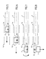
- FIG. 1 represents the supply device according to the present invention, according to its preferred embodiment.
- the feed device comprises a support for the piece 2 which is produced in the form of a tube 1, made of a refractory material, for example ceramic, quartz or alumina, made of reinforced plastic or composite material .
- This tube 1 has a diameter slightly greater than that of the slug 2 to be transferred to the injection chamber (not shown in FIG. 1 but visible at 16 in FIGS. 9 to 12) of the casting and injecting machine under pressure or to the die of a forging press.
- the tube 1 is fitted into a metal part 10 of cylindrical shape with interposition of seals, for example O-rings 11, so as to keep the tube 1 tight.
- Said cylindrical part 10 has at its bottom a nozzle 12 into which opens a pipe for supplying a protective gas.
- such a protective gas is used in the case where the device has to handle pieces made of metals, such as magnesium, capable of burning or oxidize.
- This protective gas can for example be a mixture of CO2, SF6 and air or a mixture of CO2 and SF6 without air.
- the tube 1 which has a circular or prismatic section, is provided with a cutout 5 which delimits a semi-cylindrical housing intended to receive the piece 2.
- this housing has the shape of a spoon 6.
- the cut is made over the entire length of the tube and the housing 7 of the piece then has a completely semi-cylindrical shape.
- the housing of the piece has the shape of a trough 8.
- the tube 1 has an extension which results in a significant overhang and, according to the invention, means 9 are provided in this case intended to support one of the ends of said tube.
- the part of the tube 1 provided with the cutout 5 and serving as housing for the piece to be transferred 2 has at its bottom lugs such as 13, 13 ′ made of the same material as the tube and which are intended to serve as wedges for the piece 2 to prevent the latter from moving into its housing.
- the piece 2 may tend to move if it is not not perfectly centered in the induction heating system. This phenomenon occurs more particularly in the case of pieces of very light materials for example in alloys based on magnesium.
- the presence of pins such as 13 and 13 ′ is even more important when the device handles pieces of magnesium alloy with a high lithium content (30 to 40%) which have a density of less than 1.
- end-of-travel contacts 15, 15 ′ are provided on the rod of the pneumatic translation cylinder 4 so as to ensure the starting or stopping of the heating system which is arranged around the device. food illustrated in Figure 1, as will now be described.
- the heating system can be produced in the form of an induction heating system 14, 14 ′, the coils of which are co-axial with the tube 1 and surround this last. It is of course possible to use another type of heating, for example Joule heating.
- FIGS. 5 to 8 two inductors 14, 14 ′ have been provided, but however their number can be reduced to one or be greater than 2.
- the device according to the present invention can implement a single inductor supplied by different powers and successive frequencies so as to heat the piece 2 in a time less than or close to one minute. At the end of the cycle, the piece 2 is thus brought to a homogeneous temperature which is situated between the liquidus and solidus temperatures of the metal or of the alloy constituting the piece 2.
- one of the inductors 14 is used to preheat the block 2 to the core while the second inductor 14' is used for maintaining the temperature of the piece in order to obtain a uniform temperature in the whole mass of the latter.
- a heating system for the plots is provided. These, instead of being positioned in the transfer tube 1 at room temperature, can be deposited there at a higher temperature thanks to preheating, carried out for example in a tunnel or Joule effect oven. The plots having thus previously accumulated a certain amount of heat, then take less time to be brought to the appropriate temperature by the induction heating system 14, 14 '. Thus, preheating of the order of 100 ° C or a few hundred degrees Celcius is sufficient to reduce the time of induction heating by several seconds or even by several minutes if the piece is large.
- FIGS. 5 to 8 illustrate the different successive phases of operation of the supply device according to the present invention, as illustrated in FIG. 1.
- FIG. 6 represents the piece 2 which has passed from position A (FIG. 5) to position B under the effect of a translation obtained by the jack 3, the position B of the piece 2 being centered in the second inductor 14 ′ . In this position, the plot temperature is completely homogeneous.
- FIG. 7 shows the slug 2 in position C, taken out of the second inductor 14 ′, the tube 1 having continued its translation along its axis 1, under the effect of the jack 3.
- FIG. 8 represents the tube 1 having undergone a rotation of half a turn thanks to the rotation cylinder 4, the slug 2 then leaving its housing of the tube 1 (position D) to fall in free fall directly in the injection chamber or in the press die, located under its housing, vertical to the latter, not shown in FIG. 8 but visible at 16 in particular in FIG. 9.
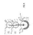
- FIG. 9 illustrates a variant of the invention comprising two supply devices of the type illustrated by the figures previous.
- these two supply devices are superimposed vertically, their axes being located in the vertical plane passing through the axis of the injection chamber 16 or in the press die.
- the tubes of the two supply systems with their supply line 17, 17 ' have been shown schematically in 1 and 1 ′, with a coating product, the respective plots being represented in 2, 2 ′.
- these means can be made in the form of infrared cells or proximity and passage sensors.
- a signal immediately gives the order to initiate the injection (or the lowering of the press punch) using a piston (not shown) disposed in the chamber 16.
- the latter has holes for heating resistors as shown in 24.
- a pipe 20 is also provided for bring a poteyage product in the form of powder or liquid in the injection chamber 16 in order to avoid any sticking of the slug in the latter.
- FIG. 9 illustrates a device which makes it possible to start the heating of a plot 2 'while the other plot 2 is already half-time reheating. Also, the positions A, B, C, D, E, F are those relating to FIGS. 5 to 8.
- the slug 2 At the end of approximately one minute, the slug 2 'leaves the inductor in position B to pass into position C (see FIG. 7), then undergo a rotation of a half-turn and finally fall directly into the injection chamber 16 (as illustrated in FIG. 8).
- the injection as described above, takes place immediately and a molded part is obtained.
- the piece 2 goes to position B and a third piece has been loaded in the feeding device located below and it starts to heat in position A.
- the second piece 2 goes to position C, (see figure 7), then it undergoes a rotation of half a turn and finally falls into the injection chamber (see figure 8) and so right now.
- the tube 1 of the supply device undergoes a rotation of half a turn in the opposite direction under the effect of the rotation cylinder 4 and it is immediately recharged with the help with a new plot.
- the casting was carried out under pressure of a part, its cooling, its ejection, the cleaning of the mold in the open position using the tube 23, preferably using a mixture consisting of powders in the case of plots of semi-solid or semi-liquid alloys, and closing the mold.
- the present invention it is possible to work in masked time and further increase the injection rate (or the forging rate in the case of application of the invention to a forging press) by superimposition of a plurality of devices identical to that illustrated in FIGS. 5 to 8, which makes it possible to ensure production rates identical to those which are usually obtained with materials in the liquid state. Thanks to the invention, it has even been possible to heat a piece of magnesium alloy (AZ 91) in about one minute with a single inductor. The great advantage of the invention is that it makes it possible to operate without a molten bath, and therefore safely in the case of flammable alloys.
- the device according to the present invention can be used for reheating and transferring pieces of plastic material loaded with an electrically conductive material, for example ABS filled with coke or conductive polymers loaded with carbon or metallic fibers. and also carbon black. Some of these materials are said to be difficult to inject.
- the conventional screw machines currently used cause significant shearing which results in the reduction of 1 or 2 orders of magnitude in the conductivity of molded parts made of conductive polymers.
- the device of the present invention makes it possible to avoid this drawback, it also allows rapid reheating which also avoids prolonged exposure to high temperature which results in an irreversible reduction of the conductivity. This device thus makes the material capable of being heated by induction.
- the device according to the present invention can be supplemented by providing a manipulator robot intended to grip the pieces in solid state to deposit them in the different feeding support (tube 1 and their cutout for positioning the pieces) described above. above.
- the axes of the various reheating devices such as 14 and 14 ′, be located, immediately before the initiation of the rotational movement under the action of the rotary actuator 4, substantially in the plane vertical passing through the axis of the injection chamber 16 so that the slug passes directly from its horizontal holding position into its housing 6, 7 or 8 of the tube 1, by free fall, under the effect of gravity and without any contact or intervention of any manipulator.
- the invention it is even possible to drop completely melted ingots into the injection chamber.
- the feed devices are arranged horizontally instead of being arranged vertically as described above.
- two supply devices have been provided arranged in the same horizontal plane, each of them having been shown diagrammatically by its heating inductors 14 1 and 14 2 respectively with their respective adaptation box 22 1 and 22 2 .
- the supply devices according to the invention with their respective heating inductors are not fixed as previously to the injection machine but they are mounted on a sliding carriage (not shown) moving according to the arrows F 1 and F 2 .
- This arrangement is made so that each feed device can deliver a heated piece to the single injection chamber 16.
- This same variant can of course also apply to a forging press.
- the entire supply and heating device located in position A on the right of this figure is in the heating phase and ready to pour the slug 2 into the injection chamber 16.
- the identical device located in position B on the left, looking at FIG. 10 begins to preheat another piece 2 '.
- this piece 2 ' has been reheated and after the piece 2 has been transferred to the injection chamber 16 and the supply and heating device located in position A has been brought back to the reheating position of a new slug
- the entire device located in B is moved by its sliding carriage according to arrow F 1 so as to bring the slug 2 'above the injection chamber 16 into which it is transferred by gravity, as described above, with particular reference to FIGS. 5 to 8.
- this same device is brought back to the reheating position to receive a new piece, while the other heating and supply device located at position A can supply the injection chamber 16 using the slug which was in the reheating position, this operation being carried out thanks to the presence of the sliding carriage on which is mounted each heating and slug supply device.
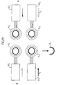
- FIG. 11 illustrates a variant of the embodiment represented by FIG. 10.
- the system has been split by superimposing two devices as illustrated in FIG. 10.
- two identical pairs have been superimposed heating and supply devices respectively 14 1 , 22 1 , 14 2 , 22 2 and 14 ' 1 , 22' 1 , 14 ' 2 , 22' 2 each mounted on a sliding carriage, in the same manner as described above above, with reference to FIG. 10, in order to obtain translational displacements according to the arrows F 1 and F2 so as to successively supply the heated chamber to the injection chamber 16.
- FIG. 12 Another possibility offered by the present invention consists in multiplying the plots heating stations by placing them on a closed curve of any shape, for example in a circle 21 as illustrated in FIG. 12, the supply devices of the type described here. above, in particular with reference to FIGS. 1 to 8 then being mounted on a turntable or on a noria type conveyor positioned on a slide allowing movement in alternative translation (advance - recoil) of the assembly.
- this figure 12 there is shown, schematically an installation according to this variant of the invention, comprising five heating stations (this number being of course not limiting), of the inductor or oven type, these stations being located in fixed position on the circle 21 respectively at A, B, C, D, E. Each of these stations corresponds to a piece feed device as specified above.
- the piece 2 in the different heating stations AD is gradually heated with different powers and possibly induction frequencies which are chosen so as to obtain a homogeneous heating of this piece when it arrives in position E immediately with its transfer into the injection chamber 16, by the supply device according to the present invention.
- the induction heating stations can be replaced by a heating tunnel or by a combination of inductors and one or more heating chambers by radiation or convection.
- the number of heating stations in the variant illustrated in FIGS. 12 and 13 can be any and not limited to 5. It will be emphasized that with a device comprising five heating stations, it is possible to achieve a higher rate, with slugs 2 in the pasty state, than that obtained by injection of liquid metal, since the temperature of the injected part is lower and therefore that its cooling time is shorter.
- the invention provides a device for transferring slugs in the solid, semi-solid, semi-liquid or liquid state, without subjecting them to deformation or loss of material, while obtaining transfer rates higher than those obtainable by the devices currently in use.
- the present invention is not limited to the exemplary embodiments described and / or mentioned here, but that it encompasses all variants thereof within the scope of the appended claims.
- the supply device according to the present invention applies not only to an injection chamber of a press-in or injection-molding machine, but also, as mentioned above. above to a forging press, for feeding the tool or the press die. All the variants described above also apply to such a forging press.
Abstract
Description
La présente invention concerne un dispositif d'alimentation d'une machine à injecter ou à couler sous pression, ou de l'outil de presse d'une machine à forger et en particulier d'une matrice de presse à forger, pour des matériaux à l'état semi-solide, solide, semi-liquide ou liquide.The present invention relates to a device for feeding a machine for injecting or casting under pressure, or the press tool of a forging machine and in particular of a die forging press, for materials to be semi-solid, solid, semi-liquid or liquid state.
Elle vise plus particulièrement le dispositif d'alimentation de la chambre d'injection d'une telle machine , ou de la matrice de presse, assurant le chauffage et le transfert de lopins en matériau métallique ou plastique, chargé ou non, ce dispositif permettant d'alimenter, de façon rapide, ladite chambre d'injection, ou ladite matrice de presse.It relates more particularly to the device for feeding the injection chamber of such a machine, or of the press die, ensuring the heating and the transfer of pieces of metal or plastic material, loaded or not, this device making it possible to 'Rapidly supplying said injection chamber or said press die.
A l'heure actuelle, on utilise des manipulateurs pour effectuer le transfert de lopins réchauffés dans la chambre d'injection des machines à couler sous pression. Ces manipulateurs sont conçus de manière à saisir le lopin réchauffé en position verticale, à la sortie du four de réchauffage, pour le transférer dans la chambre d'injection. Les inconvénients de cette solution antérieure sont nombreux, notamment :
- le lopin réchauffé en position verticale a tendance à s'avachir compte-tenu de son élancement vers le haut ;
- le lopin risque de subir des déformations lors de sa préhension par le manipulateur ;
- le temps de transfert entre le four de réchauffage et la chambre d'injection est trop long ;
- il se produit une perte de matière durant le transfert ;
- le réchauffage d'un lopin dure plusieurs minutes, ce qui est inacceptable pour des lopins constitués de métaux tels que le magnésium qui brûlent ou s'oxydent en fin de réchauffage et ,
- la mise sous atmosphère protectrice est compliquée.
- the piece heated in the vertical position tends to loosen due to its slenderness upwards;
- the piece risks being subjected to deformations when it is gripped by the manipulator;
- the transfer time between the reheating furnace and the injection chamber is too long;
- there is a loss of material during the transfer;
- reheating a piece lasts several minutes, which is unacceptable for pieces made of metals such as magnesium which burn or oxidize at the end of heating and,
- putting in a protective atmosphere is complicated.
L'article de Francis Quigley « Economical Casting of Ferrous Alloys publié dans « MANUFACTURlNG TECHNOLOGY NOTE », juillet 1979 NTN 79/0682 décrit une technique d'alimentation d'une machine à injecter dans laquelle le lopin semi-solide est réchauffer en position verticale puis est délivré par l'intermédiaire d'un toboggan dans un système d'alimentation du type à piston de la Chambre d'injection d'une machine à couler. Cette technique antérieure présente un certain nombre d'inconvénients relatifs notamment au chauffage en position verticale ainsi qu'au transfert le long d'un toboggan qui entraîne des frottements se traduisant par une déformation du lopin. Cette technique ne donne donc pas satisfaction.Francis Quigley's article "Economical Casting of Ferrous Alloys published in" MANUFACTURlNG TECHNOLOGY NOTE ", July 1979 NTN 79/0682 describes a technique for feeding an injection machine in which the semi-solid piece is heated up in a vertical position then is delivered via a slide in a piston type supply system of the injection chamber of a casting machine. This prior art has a number of drawbacks relating in particular to heating in a vertical position as well as to the transfer along a slide which causes friction resulting in a deformation of the piece. This technique is therefore not satisfactory.
Il existe d'autres dispositifs qui sont conçus de façon à pousser le lopin à l'aide d'un piston, pour l'amener dans la chambre d'injection, ces dispositifs présentant un risque de déformation du lopin lorsque ce dernier est à l'état pateux, ce qui se traduit par une perte de matière.There are other devices which are designed so as to push the slug with the aid of a piston, to bring it into the injection chamber, these devices presenting a risk of deformation of the slug when the latter is at 'pasty state, which results in a loss of material.
Enfin, on connaît d'autres dispositifs réalisés de manière à délivrer le lopin en le faisant tourner le long d'un plan incliné. Ces dispositifs connus présentent également le risque d'une déformation du lopin lors de sa phase de roulage. Par ailleurs, ces dispositifs exigent un temps de transfert trop important.Finally, other devices are known which are made so as to deliver the piece by rotating it along an inclined plane. These known devices also present the risk of deformation of the piece during its rolling phase. Furthermore, these devices require too long a transfer time.
La présente invention se propose d'apporter un dispositif qui pallie les inconvénients des solutions antérieures brièvement rappelées ci-dessus.The present invention proposes to provide a device which overcomes the drawbacks of the previous solutions briefly recalled above.
Cette invention a donc pour objet un dispositif d'alimentation d'une chambre d'injection d'une machine à couler ou à injecter sous pression ou d'un outil de presse ou d'une matrice de presse à forger assurant le transfert d'un lopin en matériau métallique ou plastique, chargé ou non, à l'état liquide, solide, semi-liquide ou semi-solide qui comporte un support à axe horizontal recevant et logeant le lopin et des moyens pour déplacer ledit support en vue d'assurer le transfert du lopin dans la chambre d'injection ou dans la matrice de presse, caractérisé en ce que ledit support est positionné dans au moins un système de chauffage et en ce que lesdits moyens pour assurer le transfert du lopin sont constitués d'une part de moyens déplaçant ledit support selon un mouvement de translation horizontale transportant ledit lopin de la position chauffage jusqu'à une position située à la verticale de la chambre d'injection ou de la matrice de presse et d'autre part, de moyens pour déplacer ledit support selon un mouvement de rotation autour de son axe afin d'entraîner la chute du lopin, toujours en position horizontale, par gravité, dudit support dans ladite chambre d'injection, ou dans la matrice de presse.The subject of this invention is therefore a device for supplying an injection chamber of a casting or injecting machine under pressure or of a tool press or a forging press die ensuring the transfer of a piece of metallic or plastic material, loaded or not, in the liquid, solid, semi-liquid or semi-solid state which comprises a support with horizontal axis receiving and housing the piece and means for moving said support in order to ensure the transfer of the piece in the injection chamber or in the press die, characterized in that said support is positioned in at least one heating system and in that said means for transferring the slug consist on the one hand of means moving said support in a horizontal translational movement transporting said slug from the heating position to a position situated vertical to the injection chamber or of the press die and on the other hand, means for moving said support in a rotational movement around its axis in order to cause the fall of the piece, still in a horizontal position, by gra vity, from said support in said injection chamber, or in the press die.
Selon l'invention, ledit support est constitué d'un tube, pouvant présenter une section circulaire ou prismatique, réalisé en un matériau réfractaire et dont le diamètre est légèrement supérieur à celui du lopin à transférer. Ce tube comporte une découpe qui délimite un logement de forme sensiblement semi-cylindrique pour recevoir le lopin. Cette découpe peut être réalisée de façon à délimiter un logement en forme de cuillère, ou en forme d'auge, et elle peut être éventuellement pratiquée sur toute la longueur du tube.According to the invention, said support consists of a tube, which may have a circular or prismatic section, made of a refractory material and whose diameter is slightly greater than that of the piece to be transferred. This tube has a cutout which delimits a housing of substantially semi-cylindrical shape to receive the piece. This cutting can be carried out so as to delimit a spoon-shaped or trough-shaped housing, and it can optionally be performed over the entire length of the tube.
Selon l'invention, le tube recevant le lopin est emmanché dans une pièce métallique de forme cylindrique, avec interposition de joints par exemple toriques, afin de maintenir ledit tube serré dans cette pièce métallique. Cette dernière peut être percée d'un ajutage raccordé à une conduite d'amenée d'un gaz protecteur.According to the invention, the tube receiving the piece is fitted into a metal part of cylindrical shape, with interposition of seals, for example O-rings, in order to keep said tube tight in this metal part. The latter can be pierced with a nozzle connected to a supply line of a protective gas.
Selon une caractéristique de l'invention, la pièce métallique maintenant serré ledit tube est montée sur un vérin pneumatique qui communique au tube un mouvement de rotation par rapport à son axe, ce vérin pneumatique rotatif étant lui-même monté à l'extrémité d'un vérin communiquant audit tube un mouvement de translation alternatif (avant-arrière) selon son axe.According to a characteristic of the invention, the metal part now clamped said tube is mounted on a pneumatic cylinder which communicates to the tube a rotational movement relative to its axis, this pneumatic cylinder rotary being itself mounted at the end of a jack communicating to said tube an alternative translational movement (front-rear) along its axis.
Selon l'invention, ledit tube recevant le lopin est positionné dans au moins un système de chauffage par induction ou par effet Joule, les axes des systèmes de chauffage étant situés, juste avant le déclenchement du mouvement de rotation du tube, sensiblement dans le plan vertical passant par l'axe de la chambre d'injection ou de la matrice de presse.According to the invention, said tube receiving the piece is positioned in at least one heating system by induction or by Joule effect, the axes of the heating systems being located, just before the initiation of the rotation movement of the tube, substantially in the plane vertical passing through the axis of the injection chamber or the press die.
Selon un autre aspect de cette invention, celle-ci a pour objet une machine à couler ou à injecter sous pression, ou une presse à forger pour matériau à l'état liquide, semi-solide ou semi-liquide caractérisée en ce qu'elle comporte une pluralité de dispositifs d'alimentation tels que définis ci-dessus.According to another aspect of this invention, the subject of the invention is a machine for casting or injecting under pressure, or a forging press for material in the liquid, semi-solid or semi-liquid state, characterized in that it comprises a plurality of supply devices as defined above.
D'autres caractéristiques de l'invention sont définies dans les revendications annexées à la présente description.Other characteristics of the invention are defined in the claims appended to this description.
On décrira maintenant des exemples de réalisation de la présente invention en se référant aux dessins annexés. Il demeure bien entendu que ces exemples n'ont aucun caractère limitatif.Examples of embodiments of the present invention will now be described with reference to the accompanying drawings. It goes without saying that these examples are in no way limiting.
Sur les dessins :
- La figure 1 est une vue schématique en perspective d'un premier exemple de réalisation du dispositif d'alimentation selon la présente invention ;
- Les figures 2 à 4 sont des vues schématiques partielles, en perspective de diverses variantes du support de lopin utilisé dans le dispositif d'alimentation selon l'invention.
- Les figures 5 à 8 sont des vues schématiques en élévation latérale illustrant les diverses phases de fonctionnement du dispositif d'alimentation selon la présente invention ;
- Figure 1 is a schematic perspective view of a first embodiment of the supply device according to the present invention;
- Figures 2 to 4 are partial schematic views, in perspective of various variants of the plot support used in the feed device according to the invention.
- Figures 5 to 8 are schematic side elevational views illustrating the various operating phases of the supply device according to the present invention;
La figure 9 illustre une variante de l'invention mettant en oeuvre deux dispositifs d'alimentation, cette figure étant une vue schématique en coupe verticale transversale ;FIG. 9 illustrates a variant of the invention using two supply devices, this figure being a schematic view in vertical transverse section;
Les figures 10 à 12 sont des vues schématiques similaires à la figure 9 illustrant diverses variantes de l'invention mettant en oeuvre une pluralité de dispositifs d'alimentation et,FIGS. 10 to 12 are schematic views similar to FIG. 9 illustrating various variants of the invention using a plurality of supply devices and,
La figure 13 illustre les séquences de fonctionnement de la variante de l'invention illustrée par la figure 12.FIG. 13 illustrates the operating sequences of the variant of the invention illustrated by FIG. 12.
On se réfère en premier lieu à la figure 1 qui représente le dispositif d'alimentation selon la présente invention, selon son mode d'exécution préféré.Reference is firstly made to FIG. 1 which represents the supply device according to the present invention, according to its preferred embodiment.
Dans cet exemple de réalisation, le dispositif d'alimentation comprend un support pour le lopin 2 qui est réalisé sous la forme d'un tube 1, en un matériau réfractaire, par exemple en céramique, quartz ou alumine, en matériau composite ou plastique renforcé. Ce tube 1 présente un diamètre légèrement supérieur à celui du lopin 2 devant être transféré vers la chambre d'injection (non représentée sur la figure 1 mais visible en 16 sur les figures 9 à 12) de la machine à couler et à injecter sous pression ou vers la matrice d'une presse à forger. Le tube 1 est emmanché dans une pièce métallique 10 de forme cylindrique avec interposition de joints, par exemple toriques 11, de manière à maintenir le tube 1 serré. Ladite pièce cylindrique 10 comporte dans son fond un ajutage 12 dans lequel débouche une conduite d'amenée d'un gaz protecteur. On utilise en effet selon l'invention un tel gaz protecteur dans le cas où le dispositif doit manipuler des lopins constitués de métaux, tel que le magnésium, susceptibles de brûler ou de s'oxyder. Ce gaz protecteur peut être par exemple un mélange de CO2, SF6 et air ou un mélange de CO2 et SF6 sans air.In this exemplary embodiment, the feed device comprises a support for the
Le tube 1, qui présente une section circulaire ou prismatique, est muni d'une découpe 5 qui délimite un logement semi-cylindrique destiné à recevoir le lopin 2. Sur la figure 1, ce logement présente la forme d'une cuillère 6. Dans la variante illustrée par la figure 2, la découpe est pratiquée sur toute la longueur du tube et le logement 7 du lopin présente alors une forme totalement semi-cylindrique. Dans la variante de l'invention illustrée par la figure 3, le logement du lopin présente la forme d'une auge 8. Dans le cas de la variante illustrée par la figure 4, le tube 1 comporte un prolongement ce qui se traduit par un porte-à-faux important et, selon l'invention, on prévoit dans ce cas des moyens 9 destinés à soutenir l'une des extrémités dudit tube.The
La partie du tube 1 munie de la découpe 5 et servant de logement au lopin à transférer 2 comporte dans son fond des ergots tels que 13, 13' réalisés en la même matière que le tube et qui sont destinés à servir de cales au lopin 2 afin d'empêcher ce dernier de se déplacer dans son logement. En effet, sous l'influence du champ magnétique développé par le système de chauffage par induction décrit ci-après (figures 5 à 8, références 14, 14'), le lopin 2 peut avoir tendance à se déplacer s'il n'est pas parfaitement centré dans le système de chauffage par induction. Ce phénomène se produit plus particulièrement dans le cas de lopins en matériaux très légers par exemple en alliages à base de magnésium. La présence des ergots tels que 13 et 13' est encore plus importante lorsque le dispositif manipule des lopins en alliage de magnésium à forte teneur en lithium (30 à 40%) qui ont une densité inférieure à 1.The part of the
Selon l'invention, on prévoit au-dessus de l'extrémité du tube 1 muni du logement pour le lopin 2, une conduite 17 d'alimentation d'un produit de poteyage afin d'éviter tout collage du lopin dans son logement.According to the invention, there is provided above the end of the
Ainsi qu'on la expliqué dans le préambule de la présente description, le tube 1, conçu de façon à recevoir et loger le lopin 2, comporte d'une part des moyens permettant de le déplacer selon un mouvement de translation horizontale pour transporter le lopin d'une cellule de chauffage jusqu'à une position située à la verticale de la chambre d'injection ou de la matrice de presse lorsque le dispositif selon l'invention est appliqué à une machine à forger et, d'autre part des moyens pour déplacer ce tube selon un mouvement de rotation afin d'entraîner la chute du lopin, par gravité, du tube 1 dans la chambre d'injection, ou dans la matrice de presse. Dans l'exemple de réalisation illustré par la figure 1, ces moyens sont réalisés sous la forme de deux vérins :
- d'une part, un vérin pneumatique 4 communiquant au
tube 1 un mouvement de rotation par rapport à son axe schématisé en traits mixtes sur la figure 1. De préférence, ce mouvement rotatif permet de faire effectuer autube 1 un demi-tour en 0,1 sec. environ ; - d'autre part, un vérin pneumatique 3 fixé sur le vérin pneumatique de rotation 4, ce vérin 3
communiquant au tube 1 un mouvement de translation alternatif (avant ou arrière) selon l'axe de ce tube.
- on the one hand, a pneumatic cylinder 4 communicating to the tube 1 a rotational movement with respect to its axis shown schematically in phantom in Figure 1. Preferably, this rotary movement allows the
tube 1 to perform a half-turn at 0 , 1 sec. about ; - on the other hand, a pneumatic cylinder 3 fixed on the pneumatic rotation cylinder 4, this cylinder 3 communicating to the
tube 1 an alternative translational movement (front or rear) along the axis of this tube.
Selon l'invention, on prévoit des contacts de fin de course 15, 15' sur la tige du vérin pneumatique de translation 4 de manière à assurer la mise en marche ou l'arrêt du système de réchauffage qui est disposé autour du dispositif d'alimentation illustré par la figure 1, comme on le décrira maintenant.According to the invention, end-of-
Ainsi qu'on l'a représenté notamment sur les figures 5 à 8, le système de réchauffage peut être réalisé sous la forme d'un système de chauffage par induction 14, 14' dont les bobines sont co-axiales au tube 1 et entourent ce dernier. On peut bien entendu, utiliser un autre type de chauffage, par exemple un chauffage par effet Joule.As shown in particular in FIGS. 5 to 8, the heating system can be produced in the form of an
Sur les figures 5 à 8, on a prévu deux inducteurs 14, 14' mais cependant leur nombre peut être réduit à un seul ou être supérieur à 2. En effet, le dispositif selon la présente invention peut mettre en oeuvre un seul inducteur alimenté par des puissances et des fréquences successives différentes de manière à chauffer le lopin 2 en un temps inférieur ou voisin d'une minute. En fin de cycle, le lopin 2 est ainsi porté à une température homogène qui est située entre les températures de liquidus et de solidus du métal ou de l'alliage constituant le lopin 2. Lorsqu'on utilise deux inducteurs comme dans le cas de l'exemple de réalisation illustré par les figures 5 à 8, l'un des inducteurs 14 sert à préchauffer à coeur le lopin 2 alors que le second inducteur 14' est utlisé pour le maintien en température du lopin afin d'obtenir une température homogène dans toute la masse de ce dernier.In FIGS. 5 to 8, two
Selon la présente invention, on prévoit un système de réchauffage des lopins. Ceux-ci, au lieu d'être positionnés dans le tube de transfert 1 à la température ambiante, peuvent y être déposés à une température plus élevée grâce à un préchauffage, réalisé par exemple dans un four tunnel ou à effet Joule. Les lopins ayant ainsi préalablement accumulé une certaine quantité de chaleur, mettent ensuite moins longtemps pour être amenés à la température appropriée par le système de chauffage par induction 14, 14'. Ainsi, un préchauffage de l'ordre de 100°C ou de quelques centaines de degrés Celcius, est suffisant pour diminuer le temps du chauffage par induction de plusieurs secondes ou mêmes de plusieurs minutes si le lopin est de dimension importante.According to the present invention, a heating system for the plots is provided. These, instead of being positioned in the
Les figures 5 à 8 illustrent les différentes phases successives de fonctionnement du dispositif d'alimentation selon la présente invention, tel qu'illustré par la figure 1.FIGS. 5 to 8 illustrate the different successive phases of operation of the supply device according to the present invention, as illustrated in FIG. 1.
La figure 5 représente le lopin 2 dans sa position de préchauffage A au centre de l'inducteur de préchauffe 14, le lopin étant maintenu en position dans son logement du tube 1 par les ergots 13, 13'.5 shows the
La figure 6 représente le lopin 2 qui est passé de la position A (figure 5) à la position B sous l'effet d'une translation obtenue par le vérin 3, la position B du lopin 2 étant centrée dans le second inducteur 14'. Dans cette position, la température du lopin est complètement homogène.FIG. 6 represents the
La figure 7 représente le lopin 2 en position C, sorti du second inducteur 14', le tube 1 ayant poursuivi sa translation selon son axe 1, sous l'effet du vérin 3.FIG. 7 shows the
La figure 8 représente le tube 1 ayant subi une rotation d'un demi-tour grâce au vérin de rotation 4, le lopin 2 quittant alors son logement du tube 1 (position D) pour tomber en chute libre directement dans la chambre d'injection ou dans la matrice de presse, située sous son logement, à la verticale de ce dernier, non représentée sur la figure 8 mais visible en 16 notamment sur la figure 9.FIG. 8 represents the
Dès que le lopin est tombé dans la chambre d'injection 16, des moyens (décrits ci-après en référence à la figure 9) permettent de contrôler son bon positionnement dans la chambre d'injection et dès que ce contrôle a été effectué, l'injection est déclenchée. Lorsque le dispositif selon l'invention est appliqué à une presse à forger, le dispositif de transfert décrit ci-dessus fait une incursion rapide entre la matrice de la presse et le poinçon pour déverser un lopin. Dès que le dispositif de transfert est rétracté, le poinçon de la presse est libre de descendre pour effectuer l'opération de forgeage.As soon as the piece has fallen into the
On soulignera que toute les opérations illustrées par les figures 5 à 8 s'effectuent dans un temps inférieur ou voisin de la minute, ce qui permet de réchauffer un lingot en alliage de magnésium tel que l'AZ 91, sans que ce dernier ait le temps de brûler même en l'absence d'injection du gaz protecteur délivré au-travers de l'ajutage 12 (figure 1).It will be emphasized that all the operations illustrated in FIGS. 5 to 8 are carried out in a time less than or close to one minute, which makes it possible to heat an ingot made of magnesium alloy such as the AZ 91, without the latter having the time to burn even in the absence of injection of the protective gas delivered through the nozzle 12 (Figure 1).
On se réfère maintenant à la figure 9 qui illustre une variante de l'invention comportant deux dispositifs d'alimentation du type illustré par les figures précédentes. Dans cette variante, ces deux dispositifs d'alimentation sont superposés verticalement, leurs axes étant situés dans le plan vertical passant par l'axe de la chambre d'injection 16 ou dans la matrice de presse. On a schématisé en 1 et 1', les tubes des deux systèmes d'alimentation avec leur conduite d'alimentation 17, 17' d'un produit de poteyage, les lopins respectifs étant représentés en 2, 2'. Sur cette même figure 9, on a représenté en 18, les moyens prévus par l'invention pour contrôler le bon positionnement d'un lopin 2 ou 2' dans la chambre d'injection 16. Dans cet exemple de réalisation, ces moyens peuvent être réalisés sous la forme de cellules infra-rouge ou de capteurs de proximité et de passage. Dès que le contrôle du bon positionnement du lopin dans la chambre d'injection 16 (ou dans la matrice de presse) a été effectué, un signal donne immédiatement l'ordre de déclencher l'injection (ou la descente du poinçon de la presse) à l'aide d'un piston (non représenté) disposé dans la chambre 16. Cette dernière comporte des trous pour des résistances chauffantes ainsi qu'on l'a représenté en 24. Selon l'invention, on prévoit également une conduite 20 pour amener un produit de poteyage sous forme de poudre ou de liquide dans la chambre d'injection 16 afin d'éviter tout collage du lopin dans cette dernière.Reference is now made to FIG. 9 which illustrates a variant of the invention comprising two supply devices of the type illustrated by the figures previous. In this variant, these two supply devices are superimposed vertically, their axes being located in the vertical plane passing through the axis of the
Cette variante de l'invention illustrée par la figure 9 qui utilise deux dispositifs superposés G et H identiques à ceux décrits par les figures 5 à 8, la figure 9 illustre un dispositif qui permet de commencer le chauffage d'un lopin 2' alors que l'autre lopin 2 est déjà à mi-temps du réchauffage. Aussi, les positions A, B, C, D, E, F sont celles relatives aux figures 5 à 8.This variant of the invention illustrated by FIG. 9 which uses two superimposed devices G and H identical to those described by FIGS. 5 to 8, FIG. 9 illustrates a device which makes it possible to start the heating of a
Le fonctionnement de cette variante de l'invention est le suivant :
- le
premier lopin 2', en position G sur un dispositif aux figures 5 à 8 est chauffé à l'aide d'un dispositif similaire à celui décrit ci-dessus en référence aux figures 5 à 8. Au bout d'environ 30 sec., il passe en position B telle que celle du dispositif visé à la position A, lesecond lopin 2 commence à chauffer en position A avec un autre dispositif de chauffage similaire à celui illustré par les figures 5 à 8, mais positionné au-dessus en H dans un plan vertical passant par l'axe d'injection et l'axe du dispositif d'alimentation situé en dessous.
- the
first piece 2 ′, in position G on a device in FIGS. 5 to 8, is heated using a device similar to that described above with reference to FIGS. 5 to 8. After approximately 30 sec. , it goes to position B such as that of the device referred to in position A, thesecond piece 2 begins to heat in position A with another heating device similar to that illustrated by FIGS. 5 to 8, but positioned above at H in a vertical plane passing through the injection axis and the axis of the supply device located below.
A l'expiration d'une minute environ, le lopin 2' sort de l'inducteur en position B pour passer dans la position C (voir la figure 7), puis subir une rotation d'un demi-tour et finalement tomber directement dans la chambre d'injection 16 (comme illustré sur la figure 8). L'injection, comme décrit ci-dessus se produit immédiatement et l'on obtient une pièce moulée. Pendant ce temps, le lopin 2 passe en position B et un troisième lopin a été chargé dans le dispositif d'alimentation situé en dessous et il commence à chauffer en position A.At the end of approximately one minute, the
Environ trente secondes plus tard, le second lopin 2 passe en position C, (voir la figure 7), puis il subit une rotation d'un demi-tour et tombe finalement dans la chambre d'injection (voir la figure 8) et ainsi de suite. Après le déversement du lopin dans la chambre d'injection 16, le tube 1 du dispositif d'alimentation subit une rotation d'un demi-tour en sens inverse sous l'effet du vérin de rotation 4 et il est immédiatement rechargé à l'aide d'un nouveau lopin. On peut ainsi obtenir une injection toutes les 30 secondes. Pendant ces trente secondes, on a effectué la coulée sous pression d'une pièce, son refroidissement, son éjection, le poteyage du moule en position ouverte à l'aide du tube 23 en utilisant de préférence un mélange constitué de poudres dans le cas de lopins d'alliages semi-solides ou semi-liquides, et la fermeture du moule.About thirty seconds later, the
Bien entendu, la variante décrite ci-dessus en référence à la figure 9 peut également s'appliquer à une presse à forger, le dispositif de transfert assurant l'alimentation du poinçon de la presse.Of course, the variant described above with reference to Figure 9 can also be applied to a forging press, the transfer device ensuring the supply of the punch of the press.
Selon la présente invention, on peut travailler en temps masqué et augmenter encore la cadence d'injection (ou la cadence de forgeage dans le cas d'une application de l'invention à une presse à forger) par superposition d'une pluralité de dispositifs identiques à celui illustré par les figures 5 à 8, ce qui permet d'assurer des cadences de production identiques à celles qui sont habituellement obtenues avec des matériaux à l'état liquide. Grâce à l'invention, on a même réussi à réchauffer un lopin d'alliage de magnésium (AZ 91) en environ une minute avec un seul inducteur. Le grand avantage de l'invention est qu'il permet d'opérer sans bain de fusion, donc en toute sécurité dans le cas d'alliages inflammables.According to the present invention, it is possible to work in masked time and further increase the injection rate (or the forging rate in the case of application of the invention to a forging press) by superimposition of a plurality of devices identical to that illustrated in FIGS. 5 to 8, which makes it possible to ensure production rates identical to those which are usually obtained with materials in the liquid state. Thanks to the invention, it has even been possible to heat a piece of magnesium alloy (AZ 91) in about one minute with a single inductor. The great advantage of the invention is that it makes it possible to operate without a molten bath, and therefore safely in the case of flammable alloys.
Le dispositif selon la présente invention peut être utilisé pour le réchauffage et le transfert de lopins en matière plastique chargés d'un matériau conducteur de l'électricité, par exemple de l'ABS chargé au coke ou polymères conducteurs chargés de fibres de carbone ou métalliques et aussi de noir de carbone. Certains de ces matériaux sont réputés être difficile à injecter. De plus, les machines classiques à vis actuellement utilisées entraînent un cisaillement important qui a pour conséquence la réduction de 1 ou 2 ordres de grandeur dans la conductivité des pièces moulées en polymères conducteurs. Le dispositif de la présente invention permet d'éviter cet inconvénient, il permet de plus un réchauffage rapide qui évite aussi une exposition prolongée à haute température qui entraîne une réduction irréversible de la conductivité. Ce dispositif rend ainsi le matériau susceptible d'être réchauffé par induction.The device according to the present invention can be used for reheating and transferring pieces of plastic material loaded with an electrically conductive material, for example ABS filled with coke or conductive polymers loaded with carbon or metallic fibers. and also carbon black. Some of these materials are said to be difficult to inject. In addition, the conventional screw machines currently used cause significant shearing which results in the reduction of 1 or 2 orders of magnitude in the conductivity of molded parts made of conductive polymers. The device of the present invention makes it possible to avoid this drawback, it also allows rapid reheating which also avoids prolonged exposure to high temperature which results in an irreversible reduction of the conductivity. This device thus makes the material capable of being heated by induction.
Le dispositif selon la présente invention peut être complété en prévoyant un robot manipulateur destiné à saisir les lopins à l'état solide pour les déposer dans le ou les différents supports d'alimentation (tube 1 et leur découpe de positionnement des lopins) décrits ci-dessus.The device according to the present invention can be supplemented by providing a manipulator robot intended to grip the pieces in solid state to deposit them in the different feeding support (
On notera qu'il est essentiel pour l'invention que les axes des divers dispositifs de réchauffage tels que 14 et 14', soient situés, immédiatement avant le déclenchement du mouvement de rotation sous l'action du vérin rotatif 4, sensiblement dans le plan vertical passant par l'axe de la chambre d'injection 16 de manière que le lopin passe directement de sa position de maintien horizontal dans son logement 6, 7 ou 8 du tube 1, par chute libre, sous l'effet de la gravité et sans aucun contact ni intervention d'un quelconque manipulateur. Ainsi, grâce à l'invention, il est même possible de faire tomber dans la chambre d'injection des lingots complètement fondus.It will be noted that it is essential for the invention that the axes of the various reheating devices such as 14 and 14 ′, be located, immediately before the initiation of the rotational movement under the action of the rotary actuator 4, substantially in the plane vertical passing through the axis of the
Dans la variante de l'invention illustrée par la figure 10, les dispositifs d'alimentation sont disposés horizontalement au lieu d'être disposés verticalement comme décrit ci-dessus. Selon cette figure 10, on a prévu deux dispositifs d'alimentation disposés dans le même plan horizontal chacun d'eux ayant été schématisés par ses inducteurs de chauffage respectivement 141 et 142 avec leur coffret d'adaptation respectif 221 et 222.In the variant of the invention illustrated in FIG. 10, the feed devices are arranged horizontally instead of being arranged vertically as described above. According to this FIG. 10, two supply devices have been provided arranged in the same horizontal plane, each of them having been shown diagrammatically by its
Dans cette variante, les dispositifs d'alimentation selon l'invention avec leurs inducteurs de chauffage respectifs ne sont pas fixés comme précédemment à la machine d'injection mais ils sont montés sur un chariot coulissant (non représenté) se déplaçant selon les flèches F1 et F2 . Cette disposition est réalisée de manière que chaque dispositif d'alimentation puisse délivrer un lopin réchauffé à la chambre d'injection unique 16. Cette même variante peut bien entendu s'appliquer également à une presse à forger.In this variant, the supply devices according to the invention with their respective heating inductors are not fixed as previously to the injection machine but they are mounted on a sliding carriage (not shown) moving according to the arrows F 1 and F 2 . This arrangement is made so that each feed device can deliver a heated piece to the
Sur cette figure 10, l'ensemble du dispositif d'alimentation et de chauffage situé en position A sur la droite de cette figure est en phase de chauffage et prêt à déverser le lopin 2 dans la chambre d'injection 16. Pendant ce temps, le dispositif identique situé en position B sur la gauche en regardant la figure 10, commence à préchauffer un autre lopin 2'. Lorsque ce lopin 2' a été réchauffé et après que le lopin 2 ait été transféré dans la chambre d'injection 16 et que le dispositif d'alimentation et de chauffage situé en position A ait été ramené dans la position de réchauffage d'un nouveau lopin, l'ensemble du dispositif situé en B est déplacé grâce à son chariot coulissant selon la flèche F1 de manière à amener le lopin 2' au-dessus de la chambre d'injection 16 dans lequel il est transféré par gravité, comme décrit ci-dessus, en référence notamment au figure 5 à 8. Ensuite, ce même dispositif est ramené en position de réchauffage pour recevoir un nouveau lopin, cependant que l'autre dispositif de chauffage et d'alimentation situé en position A peut alimenter la chambre d'injection 16 à l'aide du lopin qui était en position de réchauffage, cette opération étant réalisée grâce à la présence du chariot coulissant sur lequel est monté chaque dispositif de chauffage et d'alimentation de lopin.In this FIG. 10, the entire supply and heating device located in position A on the right of this figure is in the heating phase and ready to pour the
La figure 11 illustre une variante du mode de réalisation représenté par la figure 10. Dans cette variante, on a dédoublé le système en superposant deux dispositifs tels qu'illustrés par la figure 10. Ainsi, dans cette variante, on a superposé deux paires identiques de dispositifs de chauffage et d'alimentation respectivement 141, 221, 142, 222 et 14'1, 22'1, 14'2, 22'2 montées chacune sur chariot coulissant, de la même manière que décrite ci-dessus, en référence à la figure 10, pour obtenir des déplacements en translation selon les flèches F1 et F2 de façon à alimenter successivement en lopins réchauffés la chambre d'injection 16.FIG. 11 illustrates a variant of the embodiment represented by FIG. 10. In this variant, the system has been split by superimposing two devices as illustrated in FIG. 10. Thus, in this variant, two identical pairs have been superimposed heating and supply devices respectively 14 1 , 22 1 , 14 2 , 22 2 and 14 ' 1 , 22' 1 , 14 ' 2 , 22' 2 each mounted on a sliding carriage, in the same manner as described above above, with reference to FIG. 10, in order to obtain translational displacements according to the arrows F 1 and F2 so as to successively supply the heated chamber to the
Une autre possibilité offerte par la présente invention consiste à multiplier les postes de réchauffage de lopins en les disposant sur une courbe fermée de forme quelconque, par exemple selon un cercle 21 comme illustré par la figure 12, les dispositifs d'alimentation du type décrit ci-dessus, notamment en référence aux figures 1 à 8 étant alors montés sur un plateau tournant ou sur un transporteur du type noria positionné sur une coulisse permettant un déplacement en translation alternative (avance - recul ) de l'ensemble. Sur cette figure 12, on a représenté, de façon schématique une installation selon cette variante de l'invention, comportant cinq postes de chauffage (ce nombre n'étant bien entendu pas limitatif), du type inducteur ou four, ces postes étant situés en position fixe sur le cercle 21 respectivement en A, B, C, D, E. A chacun de ces postes correspond un dispositif d'alimentation en lopin comme spécifié ci-dessus.Another possibility offered by the present invention consists in multiplying the plots heating stations by placing them on a closed curve of any shape, for example in a
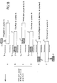
La séquence de fonctionnement de ce dispositif a été indiquée sur le schéma de la figure 13. Il est le suivant :
- un dispositif d'alimentation en lopins est en position rétractée arrière dans laquelle il reçoit un lopin froid 2 qui est positionné dans le logement du dispositif d'alimentation (tube 1) par l'intermédiaire d'un système de chargement (non représenté) ;
- le dispositif d'alimentation est ensuite amené en position A dans laquelle le lopin 2 est réchauffé par le ou les inducteurs 14 ;
- ce dispositif d'alimentation est ensuite rétracté à partir de la position A afin de dégager le lopin précedemment réchauffé en l'éloignant du système de réchauffage 14, et pour passer en regard de la position B, par rotation d'un cinquième de tour du plateau tournant sur lequel est monté ce dispositif d'alimentation ;
- le dispositif d'alimentation subit alors une nouvelle translation pour amener le lopin 2 en position B où se poursuit son réchauffage par le dispositif d'inducteurs 14;
- les mêmes opérations que décrites ci-dessus se répètent ensuite pour réaliser les passages successifs de B à C, de C à D et de D à E ;
- enfin, dans la position E, le lopin 2 subit un chauffage final puis il est déchargé dans la chambre d'injection 16, de la manière décrite ci-dessus en référence notamment aux figures 7
et 8.
- a block supply device is in the rear retracted position in which it receives a
cold block 2 which is positioned in the housing of the feed device (tube 1) via a loading system (not shown); - the feed device is then brought into position A in which the
slug 2 is heated by the inductor (s) 14; - this feeding device is then retracted from position A in order to release the previously heated piece away from the
heating system 14, and to pass opposite position B, by rotation of a fifth of a turn of the turntable on which this feeding device is mounted; - the feed device then undergoes a new translation to bring the
slug 2 to position B where its heating continues by theinductor device 14; - the same operations as described above are then repeated to carry out the successive passages from B to C, from C to D and from D to E;
- finally, in position E, the
slug 2 undergoes final heating then it is discharged into theinjection chamber 16, in the manner described above with reference in particular to FIGS. 7 and 8.
Grâce à ce mode de réalisation, le lopin 2, dans les différents postes de chauffage A-D, est chauffé progressivement avec des puissances et éventuellement des fréquences d'induction différentes qui sont choisies de manière à obtenir un chauffage homogène de ce lopin lorsqu'il arrive en position E immédiatement avec son transfert dans la chambre d'injection 16, par le dispositif d'alimentation selon la présente invention.Thanks to this embodiment, the
Selon encore un autre exemple de réalisation du dispositif objet de cette invention, les postes de chauffage par induction peuvent être remplacés par un tunnel chauffant ou par une combinaison d'inducteurs et d'une ou plusieurs enceintes chauffantes par rayonnement ou convection. Comme on l'a précisé ci-dessus, le nombre de postes de chauffage dans la variante illustrée par les figures 12 et 13 peut être quelconque et non limité à 5. On soulignera qu'avec un dispositif comportant cinq postés de chauffage, il est possible d'atteindre une cadence supérieure, avec des lopins 2 à l'état pâteux, à celle obtenue par injection de métal liquide, étant donné que la température de la pièce injectée est inférieure et donc que son temps de refroidissement est plus court.According to yet another embodiment of the device which is the subject of this invention, the induction heating stations can be replaced by a heating tunnel or by a combination of inductors and one or more heating chambers by radiation or convection. As specified above, the number of heating stations in the variant illustrated in FIGS. 12 and 13 can be any and not limited to 5. It will be emphasized that with a device comprising five heating stations, it is possible to achieve a higher rate, with
Il résulte de la lecture de la description qui précède que l'invention apporte un dispositif permettant de transférer des lopins à l'état solide, semi-solide, semi-liquide ou liquide, sans leur faire subir de déformation ou de perte de matière, tout en obtenant des cadences de transfert supérieures à celles pouvant être obtenues par les dispositifs actuellement utilisés.It follows from reading the above description that the invention provides a device for transferring slugs in the solid, semi-solid, semi-liquid or liquid state, without subjecting them to deformation or loss of material, while obtaining transfer rates higher than those obtainable by the devices currently in use.
Il demeure bien entendu que la présente invention n'est pas limitée aux exemples de réalisation décrits et/ou mentionnés ici, mais qu'elle en englobe toutes les variantes dans le cadre des revendications annexées. C'est ainsi notamment que le dispositif d'alimentation selon la présente invention s'applique non seulement à une chambre d'injection d'une machine à couler ou à injecter sous pression mais également, ainsi qu'on l'a mentionné ci-dessus à une presse à forger, pour l'alimentation de l'outil ou de la matrice de presse. Toutes les variantes décrites ci-dessus s'appliquent également à une telle presse à forger.It remains to be understood that the present invention is not limited to the exemplary embodiments described and / or mentioned here, but that it encompasses all variants thereof within the scope of the appended claims. Thus, in particular, the supply device according to the present invention applies not only to an injection chamber of a press-in or injection-molding machine, but also, as mentioned above. above to a forging press, for feeding the tool or the press die. All the variants described above also apply to such a forging press.
Claims (26)
Applications Claiming Priority (2)
| Application Number | Priority Date | Filing Date | Title |
|---|---|---|---|
| FR9606364 | 1996-05-22 | ||
| FR9606364A FR2748957B1 (en) | 1996-05-22 | 1996-05-22 | PRESSURE INJECTION OR CASTING MACHINE |
Publications (2)
| Publication Number | Publication Date |
|---|---|
| EP0808680A1 true EP0808680A1 (en) | 1997-11-26 |
| EP0808680B1 EP0808680B1 (en) | 1999-08-11 |
Family
ID=9492357
Family Applications (1)
| Application Number | Title | Priority Date | Filing Date |
|---|---|---|---|
| EP97400971A Expired - Lifetime EP0808680B1 (en) | 1996-05-22 | 1997-04-29 | Apparatus for injecting or casting under pressure |
Country Status (9)
| Country | Link |
|---|---|
| US (1) | US6089846A (en) |
| EP (1) | EP0808680B1 (en) |
| JP (1) | JPH1071421A (en) |
| AT (1) | ATE183121T1 (en) |
| AU (1) | AU713768B2 (en) |
| CA (1) | CA2204841A1 (en) |
| DE (2) | DE808680T1 (en) |
| ES (1) | ES2134670T3 (en) |
| FR (1) | FR2748957B1 (en) |
Cited By (1)
| Publication number | Priority date | Publication date | Assignee | Title |
|---|---|---|---|---|
| DE10033165C1 (en) * | 2000-07-07 | 2002-02-07 | Hengst Walter Gmbh & Co Kg | Device and method for melting and conveying material |
Families Citing this family (14)
| Publication number | Priority date | Publication date | Assignee | Title |
|---|---|---|---|---|
| DE19926653B4 (en) * | 1999-06-11 | 2005-12-15 | Audi Ag | Process for carrying out thixoforming and thixoforming device for carrying out the process |
| CA2353046C (en) * | 2000-07-11 | 2008-07-08 | Honda Giken Kogyo Kabushiki Kaisha | Method for injection molding metallic materials |
| DE10043717A1 (en) * | 2000-09-04 | 2002-03-14 | Buehler Druckguss Ag Uzwil | Process for compressive reforming of aluminum or magnesium alloys comprises conveying the liquid or liquid material from a preparation chamber into a casting chamber of a die casting machine |
| US6551405B1 (en) * | 2000-09-22 | 2003-04-22 | The Board Of Trustees Of The University Of Arkansas | Tool and method for in situ vapor phase deposition source material reloading and maintenance |
| US20030032438A1 (en) * | 2001-08-09 | 2003-02-13 | Meschia Maurilio | Network connection system for machine tools, particularly injection presses for plastics |
| US7766071B2 (en) | 2003-10-29 | 2010-08-03 | Csir | Processing of metal alloys in a semi-solid state |
| KR100554093B1 (en) * | 2004-02-04 | 2006-02-22 | 주식회사 나노캐스트코리아 | Forming apparatus for rheoforming method |
| JP2008229633A (en) * | 2007-03-16 | 2008-10-02 | Honda Motor Co Ltd | Supply method and apparatus for semi-solid metal |
| US8316541B2 (en) | 2007-06-29 | 2012-11-27 | Pratt & Whitney Canada Corp. | Combustor heat shield with integrated louver and method of manufacturing the same |
| WO2010080990A2 (en) * | 2009-01-09 | 2010-07-15 | Harper International Corporation | Automatic feed oven |
| US9604279B2 (en) * | 2012-04-13 | 2017-03-28 | Apple Inc. | Material containing vessels for melting material |
| US10197335B2 (en) * | 2012-10-15 | 2019-02-05 | Apple Inc. | Inline melt control via RF power |
| EP2957530A1 (en) * | 2014-06-17 | 2015-12-23 | Saet S.p.A. | Apparatus for induction heating of mechanical components |
| US9873151B2 (en) | 2014-09-26 | 2018-01-23 | Crucible Intellectual Property, Llc | Horizontal skull melt shot sleeve |
Citations (1)
| Publication number | Priority date | Publication date | Assignee | Title |
|---|---|---|---|---|
| WO1992013662A1 (en) * | 1991-01-30 | 1992-08-20 | Transvalor S.A. | Method and machine for moulding an alloy ingot with fine dendritic structure |
Family Cites Families (8)
| Publication number | Priority date | Publication date | Assignee | Title |
|---|---|---|---|---|
| US2852809A (en) * | 1956-04-03 | 1958-09-23 | Stephen T Miles | Device for molding plastic material |
| US3133179A (en) * | 1961-09-07 | 1964-05-12 | Ohio Crankshaft Co | Semi-automatic locating, automatic centering induction heating apparatus |
| US3877862A (en) * | 1973-11-16 | 1975-04-15 | Pennwalt Corp | Feeder for multi-cavity compression molding apparatus |
| US4017703A (en) * | 1975-12-17 | 1977-04-12 | American Induction Heating Corporation | Multiple station induction heating machine |
| CH671184A5 (en) * | 1986-11-19 | 1989-08-15 | Bucher Guyer Ag Masch | |
| DE3908265A1 (en) * | 1989-03-14 | 1990-09-20 | Leybold Ag | CHARGING DEVICE FOR MELTING PLANTS |
| IT1260684B (en) * | 1993-09-29 | 1996-04-22 | Weber Srl | METHOD AND PLANT FOR THE DIE-CASTING OF SEMI-LIQUID COMPONENTS WITH HIGH MECHANICAL PERFORMANCE STARTING FROM REOCOLATED SOLID. |
| US5872352A (en) * | 1995-03-22 | 1999-02-16 | Honda Ginken Kogyo Kabushiki Kaisha | Swingable induction heating chamber for melting ingot for metal casting |
-
1996
- 1996-05-22 FR FR9606364A patent/FR2748957B1/en not_active Expired - Lifetime
-
1997
- 1997-04-29 ES ES97400971T patent/ES2134670T3/en not_active Expired - Lifetime
- 1997-04-29 DE DE0808680T patent/DE808680T1/en active Pending
- 1997-04-29 EP EP97400971A patent/EP0808680B1/en not_active Expired - Lifetime
- 1997-04-29 AT AT97400971T patent/ATE183121T1/en not_active IP Right Cessation
- 1997-04-29 DE DE69700394T patent/DE69700394T2/en not_active Expired - Fee Related
- 1997-05-06 US US08/851,699 patent/US6089846A/en not_active Expired - Fee Related
- 1997-05-08 AU AU20101/97A patent/AU713768B2/en not_active Ceased
- 1997-05-08 CA CA002204841A patent/CA2204841A1/en not_active Abandoned
- 1997-05-22 JP JP9132319A patent/JPH1071421A/en active Pending
Patent Citations (1)
| Publication number | Priority date | Publication date | Assignee | Title |
|---|---|---|---|---|
| WO1992013662A1 (en) * | 1991-01-30 | 1992-08-20 | Transvalor S.A. | Method and machine for moulding an alloy ingot with fine dendritic structure |
Non-Patent Citations (1)
| Title |
|---|
| MANUFACTURING TECHNOLOGY NOTE, FRANCIS QUIGLEY: "Economical Casting of Ferrous Alloys", July 1979, NTN-79/0682, U.S. ARMY MATERIEL DEVELOPMENT AND READINESS COMMAND, OFFICE OF MANUFACTURING TECHNOLOGY, ALEXANDRIA, VIRGINIA, XP002025139 * |
Cited By (1)
| Publication number | Priority date | Publication date | Assignee | Title |
|---|---|---|---|---|
| DE10033165C1 (en) * | 2000-07-07 | 2002-02-07 | Hengst Walter Gmbh & Co Kg | Device and method for melting and conveying material |
Also Published As
| Publication number | Publication date |
|---|---|
| US6089846A (en) | 2000-07-18 |
| FR2748957B1 (en) | 1998-07-31 |
| DE69700394D1 (en) | 1999-09-16 |
| AU713768B2 (en) | 1999-12-09 |
| DE808680T1 (en) | 1998-05-14 |
| CA2204841A1 (en) | 1997-11-22 |
| AU2010197A (en) | 1997-11-27 |
| JPH1071421A (en) | 1998-03-17 |
| DE69700394T2 (en) | 1999-11-25 |
| EP0808680B1 (en) | 1999-08-11 |
| ATE183121T1 (en) | 1999-08-15 |
| FR2748957A1 (en) | 1997-11-28 |
| ES2134670T3 (en) | 1999-10-01 |
Similar Documents
| Publication | Publication Date | Title |
|---|---|---|
| EP0808680B1 (en) | Apparatus for injecting or casting under pressure | |
| EP2861399A1 (en) | Method and device for preheating a mold particularly intended for injection molding | |
| FR2971173A1 (en) | FOUNDRY METHOD AND INSTALLATION | |
| EP3113925B1 (en) | Preform moulding unit equipped with a rotatable core holder | |
| EP0569511B1 (en) | Method and machine for moulding an alloy ingot with fine dendritic structure | |
| FR2598961A1 (en) | DEVICE FOR FORMING THERMOPLASTIC PRODUCTS HAVING RETAILERS | |
| CA3021395C (en) | Method and device for shell-moulding a metal alloy | |
| FR2574322A1 (en) | INSTALLATION FOR PREPARING METAL BILLETS WITH FILTER | |
| FR2731934A1 (en) | HEATING MACHINE FOR CASTING METAL IN LINGOT | |
| CH625149A5 (en) | ||
| FR2527110A1 (en) | ELECTRICAL HEATING MOLD AND METHOD OF MOLDING METAL CONNECTION BARS, IN PARTICULAR FOR BATTERY ELEMENTS | |
| FR2899067A1 (en) | Nut breaking machine for separating shell from nut kernel, has cam linking and synchronizing individual transporting stages of nuts in funnel for mounting and lowering nut locking and breaking jaws, where cam is engaged with jaws | |
| EP3700695B1 (en) | Process and apparatus for bulk metallic glass casting | |
| EP0867253A1 (en) | Method and device for extracting and/or supplying the electrodes of/to an electrode gun of a resistance spot welding apparatus | |
| FR2802454A1 (en) | APPARATUS AND METHOD FOR MANUFACTURING A LIGHTWEIGHT METAL PRODUCT | |
| EP0100272B1 (en) | Process and apparatus for the production of castings, and castings produced by this process | |
| FR2500849A1 (en) | QUICK COOLING DEVICE FOR METALLIC TUBES | |
| FR2672831A1 (en) | High-rate friction welding machine | |
| WO1998042463A1 (en) | Method for making a composite part with magnesium matrix by infiltration casting | |
| BE519656A (en) | ||
| FR2488538A1 (en) | Band saw teeth renovating equipment - with renovating metal, esp. stellite, feed as preset vol. charges | |
| WO1998009914A1 (en) | Method for manufacturing synthetic diamond and device for implementing this method | |
| BE480924A (en) | ||
| FR2552350A1 (en) | METHOD AND APPARATUS FOR APPLYING A RING OF MATERIAL TO A CENTRIFUGAL CASTING MOLD | |
| BE367801A (en) |
Legal Events
| Date | Code | Title | Description |
|---|---|---|---|
| PUAI | Public reference made under article 153(3) epc to a published international application that has entered the european phase |
Free format text: ORIGINAL CODE: 0009012 |
|
| AK | Designated contracting states |
Kind code of ref document: A1 Designated state(s): AT BE CH DE DK ES FR GB IT LI NL |
|
| ITCL | It: translation for ep claims filed |
Representative=s name: BARZANO' E ZANARDO MILANO S.P.A. |
|
| GBC | Gb: translation of claims filed (gb section 78(7)/1977) | ||
| DET | De: translation of patent claims | ||
| 17P | Request for examination filed |
Effective date: 19980508 |
|
| GRAG | Despatch of communication of intention to grant |
Free format text: ORIGINAL CODE: EPIDOS AGRA |
|
| GRAG | Despatch of communication of intention to grant |
Free format text: ORIGINAL CODE: EPIDOS AGRA |
|
| GRAH | Despatch of communication of intention to grant a patent |
Free format text: ORIGINAL CODE: EPIDOS IGRA |
|
| 17Q | First examination report despatched |
Effective date: 19990114 |
|
| GRAH | Despatch of communication of intention to grant a patent |
Free format text: ORIGINAL CODE: EPIDOS IGRA |
|
| ITF | It: translation for a ep patent filed |
Owner name: INTERPATENT ST.TECN. BREV. |
|
| GRAA | (expected) grant |
Free format text: ORIGINAL CODE: 0009210 |
|
| AK | Designated contracting states |
Kind code of ref document: B1 Designated state(s): AT BE CH DE DK ES FR GB IT LI NL |
|
| PG25 | Lapsed in a contracting state [announced via postgrant information from national office to epo] |
Ref country code: NL Free format text: LAPSE BECAUSE OF FAILURE TO SUBMIT A TRANSLATION OF THE DESCRIPTION OR TO PAY THE FEE WITHIN THE PRESCRIBED TIME-LIMIT Effective date: 19990811 |
|
| REF | Corresponds to: |
Ref document number: 183121 Country of ref document: AT Date of ref document: 19990815 Kind code of ref document: T |
|
| REG | Reference to a national code |
Ref country code: CH Ref legal event code: EP |
|
| GBT | Gb: translation of ep patent filed (gb section 77(6)(a)/1977) |
Effective date: 19990726 |
|
| GBT | Gb: translation of ep patent filed (gb section 77(6)(a)/1977) |
Effective date: 19990812 |
|
| REF | Corresponds to: |
Ref document number: 69700394 Country of ref document: DE Date of ref document: 19990916 |
|
| REG | Reference to a national code |
Ref country code: ES Ref legal event code: FG2A Ref document number: 2134670 Country of ref document: ES Kind code of ref document: T3 |
|
| PG25 | Lapsed in a contracting state [announced via postgrant information from national office to epo] |
Ref country code: DK Free format text: LAPSE BECAUSE OF FAILURE TO SUBMIT A TRANSLATION OF THE DESCRIPTION OR TO PAY THE FEE WITHIN THE PRESCRIBED TIME-LIMIT Effective date: 19991111 |
|
| NLV1 | Nl: lapsed or annulled due to failure to fulfill the requirements of art. 29p and 29m of the patents act | ||
| PLBE | No opposition filed within time limit |
Free format text: ORIGINAL CODE: 0009261 |
|
| STAA | Information on the status of an ep patent application or granted ep patent |
Free format text: STATUS: NO OPPOSITION FILED WITHIN TIME LIMIT |
|
| 26N | No opposition filed | ||
| REG | Reference to a national code |
Ref country code: GB Ref legal event code: IF02 |
|
| PGFP | Annual fee paid to national office [announced via postgrant information from national office to epo] |
Ref country code: GB Payment date: 20030401 Year of fee payment: 7 |
|
| PGFP | Annual fee paid to national office [announced via postgrant information from national office to epo] |
Ref country code: FR Payment date: 20030411 Year of fee payment: 7 |
|
| PGFP | Annual fee paid to national office [announced via postgrant information from national office to epo] |
Ref country code: CH Payment date: 20030422 Year of fee payment: 7 |
|
| PGFP | Annual fee paid to national office [announced via postgrant information from national office to epo] |
Ref country code: DE Payment date: 20030423 Year of fee payment: 7 |
|
| PGFP | Annual fee paid to national office [announced via postgrant information from national office to epo] |
Ref country code: ES Payment date: 20030430 Year of fee payment: 7 Ref country code: AT Payment date: 20030430 Year of fee payment: 7 |
|
| PGFP | Annual fee paid to national office [announced via postgrant information from national office to epo] |
Ref country code: BE Payment date: 20030512 Year of fee payment: 7 |
|
| PG25 | Lapsed in a contracting state [announced via postgrant information from national office to epo] |
Ref country code: GB Free format text: LAPSE BECAUSE OF NON-PAYMENT OF DUE FEES Effective date: 20040429 Ref country code: AT Free format text: LAPSE BECAUSE OF NON-PAYMENT OF DUE FEES Effective date: 20040429 |
|
| PG25 | Lapsed in a contracting state [announced via postgrant information from national office to epo] |
Ref country code: LI Free format text: LAPSE BECAUSE OF NON-PAYMENT OF DUE FEES Effective date: 20040430 Ref country code: ES Free format text: LAPSE BECAUSE OF NON-PAYMENT OF DUE FEES Effective date: 20040430 Ref country code: CH Free format text: LAPSE BECAUSE OF NON-PAYMENT OF DUE FEES Effective date: 20040430 Ref country code: BE Free format text: LAPSE BECAUSE OF NON-PAYMENT OF DUE FEES Effective date: 20040430 |
|
| BERE | Be: lapsed |
Owner name: *CELES Effective date: 20040430 |
|
| PG25 | Lapsed in a contracting state [announced via postgrant information from national office to epo] |
Ref country code: DE Free format text: LAPSE BECAUSE OF NON-PAYMENT OF DUE FEES Effective date: 20041103 |
|
| REG | Reference to a national code |
Ref country code: CH Ref legal event code: PL |
|
| GBPC | Gb: european patent ceased through non-payment of renewal fee |
Effective date: 20040429 |
|
| PG25 | Lapsed in a contracting state [announced via postgrant information from national office to epo] |
Ref country code: FR Free format text: LAPSE BECAUSE OF NON-PAYMENT OF DUE FEES Effective date: 20041231 |
|
| REG | Reference to a national code |
Ref country code: FR Ref legal event code: ST |
|
| PG25 | Lapsed in a contracting state [announced via postgrant information from national office to epo] |
Ref country code: IT Free format text: LAPSE BECAUSE OF NON-PAYMENT OF DUE FEES;WARNING: LAPSES OF ITALIAN PATENTS WITH EFFECTIVE DATE BEFORE 2007 MAY HAVE OCCURRED AT ANY TIME BEFORE 2007. THE CORRECT EFFECTIVE DATE MAY BE DIFFERENT FROM THE ONE RECORDED. Effective date: 20050429 |
|
| REG | Reference to a national code |
Ref country code: ES Ref legal event code: FD2A Effective date: 20040430 |