EP0369891B1 - Verfahren und Gerät zum automatischen Abtasten eines Gebietes einer Oberfläche und zum Ausführen einer Bearbeitungsfunktion darauf - Google Patents
Verfahren und Gerät zum automatischen Abtasten eines Gebietes einer Oberfläche und zum Ausführen einer Bearbeitungsfunktion darauf Download PDFInfo
- Publication number
- EP0369891B1 EP0369891B1 EP89403177A EP89403177A EP0369891B1 EP 0369891 B1 EP0369891 B1 EP 0369891B1 EP 89403177 A EP89403177 A EP 89403177A EP 89403177 A EP89403177 A EP 89403177A EP 0369891 B1 EP0369891 B1 EP 0369891B1
- Authority
- EP
- European Patent Office
- Prior art keywords
- track
- working
- tool
- control circuit
- area
- Prior art date
- Legal status (The legal status is an assumption and is not a legal conclusion. Google has not performed a legal analysis and makes no representation as to the accuracy of the status listed.)
- Expired - Lifetime
Links
- 238000000034 method Methods 0.000 title claims abstract description 36
- 239000000523 sample Substances 0.000 claims abstract description 22
- 230000006870 function Effects 0.000 claims description 31
- 230000000694 effects Effects 0.000 claims description 18
- 238000003466 welding Methods 0.000 claims description 18
- 230000008439 repair process Effects 0.000 claims description 17
- 239000002184 metal Substances 0.000 claims description 14
- 230000001788 irregular Effects 0.000 claims description 10
- 238000006073 displacement reaction Methods 0.000 claims description 9
- 239000000463 material Substances 0.000 claims description 6
- 238000011065 in-situ storage Methods 0.000 claims description 5
- 230000008878 coupling Effects 0.000 claims description 4
- 238000010168 coupling process Methods 0.000 claims description 4
- 238000005859 coupling reaction Methods 0.000 claims description 4
- 238000012544 monitoring process Methods 0.000 claims 3
- 230000001419 dependent effect Effects 0.000 claims 1
- 230000006378 damage Effects 0.000 description 7
- 238000010276 construction Methods 0.000 description 3
- 238000010586 diagram Methods 0.000 description 3
- 238000013459 approach Methods 0.000 description 2
- 238000012986 modification Methods 0.000 description 2
- 230000004048 modification Effects 0.000 description 2
- 238000005476 soldering Methods 0.000 description 2
- 230000002411 adverse Effects 0.000 description 1
- 239000011324 bead Substances 0.000 description 1
- 238000004891 communication Methods 0.000 description 1
- 230000003750 conditioning effect Effects 0.000 description 1
- 238000004070 electrodeposition Methods 0.000 description 1
- 230000007613 environmental effect Effects 0.000 description 1
- 230000003628 erosive effect Effects 0.000 description 1
- 238000001914 filtration Methods 0.000 description 1
- 239000011888 foil Substances 0.000 description 1
- 239000003517 fume Substances 0.000 description 1
- 239000000383 hazardous chemical Substances 0.000 description 1
- 231100000206 health hazard Toxicity 0.000 description 1
- 238000002789 length control Methods 0.000 description 1
- 238000013507 mapping Methods 0.000 description 1
- 239000011159 matrix material Substances 0.000 description 1
- 230000007246 mechanism Effects 0.000 description 1
- 239000002245 particle Substances 0.000 description 1
- 229920003023 plastic Polymers 0.000 description 1
- 239000004033 plastic Substances 0.000 description 1
- 230000036544 posture Effects 0.000 description 1
- 230000008569 process Effects 0.000 description 1
- 238000004886 process control Methods 0.000 description 1
- 238000012545 processing Methods 0.000 description 1
- 230000005855 radiation Effects 0.000 description 1
- 230000003252 repetitive effect Effects 0.000 description 1
- 230000009528 severe injury Effects 0.000 description 1
- 229910000679 solder Inorganic materials 0.000 description 1
- 239000000725 suspension Substances 0.000 description 1
- 238000013519 translation Methods 0.000 description 1
- 238000009423 ventilation Methods 0.000 description 1
Images


Classifications
-
- B—PERFORMING OPERATIONS; TRANSPORTING
- B23—MACHINE TOOLS; METAL-WORKING NOT OTHERWISE PROVIDED FOR
- B23P—METAL-WORKING NOT OTHERWISE PROVIDED FOR; COMBINED OPERATIONS; UNIVERSAL MACHINE TOOLS
- B23P23/00—Machines or arrangements of machines for performing specified combinations of different metal-working operations not covered by a single other subclass
- B23P23/04—Machines or arrangements of machines for performing specified combinations of different metal-working operations not covered by a single other subclass for both machining and other metal-working operations
-
- G—PHYSICS
- G05—CONTROLLING; REGULATING
- G05B—CONTROL OR REGULATING SYSTEMS IN GENERAL; FUNCTIONAL ELEMENTS OF SUCH SYSTEMS; MONITORING OR TESTING ARRANGEMENTS FOR SUCH SYSTEMS OR ELEMENTS
- G05B19/00—Programme-control systems
- G05B19/02—Programme-control systems electric
- G05B19/42—Recording and playback systems, i.e. in which the programme is recorded from a cycle of operations, e.g. the cycle of operations being manually controlled, after which this record is played back on the same machine
- G05B19/4202—Recording and playback systems, i.e. in which the programme is recorded from a cycle of operations, e.g. the cycle of operations being manually controlled, after which this record is played back on the same machine preparation of the programme medium using a drawing, a model
- G05B19/4207—Recording and playback systems, i.e. in which the programme is recorded from a cycle of operations, e.g. the cycle of operations being manually controlled, after which this record is played back on the same machine preparation of the programme medium using a drawing, a model in which a model is traced or scanned and corresponding data recorded
-
- G—PHYSICS
- G05—CONTROLLING; REGULATING
- G05B—CONTROL OR REGULATING SYSTEMS IN GENERAL; FUNCTIONAL ELEMENTS OF SUCH SYSTEMS; MONITORING OR TESTING ARRANGEMENTS FOR SUCH SYSTEMS OR ELEMENTS
- G05B2219/00—Program-control systems
- G05B2219/30—Nc systems
- G05B2219/39—Robotics, robotics to robotics hand
- G05B2219/39468—Changeable hand, tool, code carrier, detector
-
- G—PHYSICS
- G05—CONTROLLING; REGULATING
- G05B—CONTROL OR REGULATING SYSTEMS IN GENERAL; FUNCTIONAL ELEMENTS OF SUCH SYSTEMS; MONITORING OR TESTING ARRANGEMENTS FOR SUCH SYSTEMS OR ELEMENTS
- G05B2219/00—Program-control systems
- G05B2219/30—Nc systems
- G05B2219/45—Nc applications
- G05B2219/45104—Lasrobot, welding robot
-
- G—PHYSICS
- G05—CONTROLLING; REGULATING
- G05B—CONTROL OR REGULATING SYSTEMS IN GENERAL; FUNCTIONAL ELEMENTS OF SUCH SYSTEMS; MONITORING OR TESTING ARRANGEMENTS FOR SUCH SYSTEMS OR ELEMENTS
- G05B2219/00—Program-control systems
- G05B2219/30—Nc systems
- G05B2219/49—Nc machine tool, till multiple
- G05B2219/49362—Tool, probe at constant height to surface during machining
-
- G—PHYSICS
- G05—CONTROLLING; REGULATING
- G05B—CONTROL OR REGULATING SYSTEMS IN GENERAL; FUNCTIONAL ELEMENTS OF SUCH SYSTEMS; MONITORING OR TESTING ARRANGEMENTS FOR SUCH SYSTEMS OR ELEMENTS
- G05B2219/00—Program-control systems
- G05B2219/30—Nc systems
- G05B2219/50—Machine tool, machine tool null till machine tool work handling
- G05B2219/50153—Mount machining unit on workpiece, move unit on it
-
- G—PHYSICS
- G05—CONTROLLING; REGULATING
- G05B—CONTROL OR REGULATING SYSTEMS IN GENERAL; FUNCTIONAL ELEMENTS OF SUCH SYSTEMS; MONITORING OR TESTING ARRANGEMENTS FOR SUCH SYSTEMS OR ELEMENTS
- G05B2219/00—Program-control systems
- G05B2219/30—Nc systems
- G05B2219/50—Machine tool, machine tool null till machine tool work handling
- G05B2219/50214—Refurbish, refinish, reprofile, recondition, restore, rebuild profile
-
- G—PHYSICS
- G05—CONTROLLING; REGULATING
- G05B—CONTROL OR REGULATING SYSTEMS IN GENERAL; FUNCTIONAL ELEMENTS OF SUCH SYSTEMS; MONITORING OR TESTING ARRANGEMENTS FOR SUCH SYSTEMS OR ELEMENTS
- G05B2219/00—Program-control systems
- G05B2219/30—Nc systems
- G05B2219/50—Machine tool, machine tool null till machine tool work handling
- G05B2219/50356—Tool perpendicular, normal to 3-D surface
Definitions
- the present invention relates to a method and apparatus for automatically sensing the configuration of a surface area of an object, such as a portion of a hydraulic turbine runner of a power generating station, and effecting a work function such as the repair of cavitation damage thereon, and more particularly to the use of a robotic system for the in-situ repair of such damage.
- the present invention originated by solving the problem of repairing hydraulic turbine runners in power stations which are often damaged by cavitation due to erosion. Such runners are often subjected to severe damage requiring extensive repair which is extremely costly due to the lengthy down time of the runner and because of the difficulty in effecting such repairs.
- the most economical way of repairing such turbines is to perform the work with the runner remaining in the turbine pit.
- the steps involved in the repair include air-arc gouging and/or grinding to remove unsound metal, followed by welding to fill the gouged-out areas. Finally, the weld-filled cavity must be ground to restore optimum blade profile.
- Another feature of the present invention is to provide a method and apparatus using a robotic system for automatically sensing the configuration of a surface area of an object, and effecting a work function thereon in situ.
- Another feature of the present invention is to provide a method and apparatus which is small, portable, self-programming and easily attachable to a work surface for automatically sensing the configuration of a surface area of the said surface and effecting a work function.
- Another feature of the present invention is to provide a method and apparatus for automatically sensing the configuration of a surface area of an object and effecting a work function, and wherein a robotic system is utilized which self-programs the work function and automatically effects the work thereto while providing the option of an operator intervention to command or assist in the determination and sequence of work procedures.
- Another feature of the present invention is to provide a method and apparatus for automatically sensing the configuration of a surface area of an object, such as on a hydraulic turbine runner, and effecting a work function to repair cavitation damage or imperfections thereon, and wherein said work function comprises gouging, welding and grinding.
- Another feature of the present invention is to provide a method and apparatus for automatically sensing the configuration of a surface area of an object and effecting a work function, and wherein the apparatus is substantially all automatic and easy to install and operate.
- the present invention provides an apparatus for automatically sensing the configuration of a surface area of an object, and effecting a work function thereon.
- the apparatus comprises a track connectible relative to the surface.
- a motor-actuated robot member is connectible to the track and has a motorized element provided with track coupling means engaged with the track for displacing the robot member at a predetermined rate and position along the track.
- a working arm is displaceably coupled to the robot member. The working arm has one or more working tools connectible thereto.
- a control circuit is associated with the robot member for displacing same and operating the working arm and tool.
- a sensor is connected to the working arm and has a probe to sense a distance which is measured along a normal of said surface or any surface calculated by said control circuit assumed to be representative of said surface in a delineated working environment of the robot member and working arm.
- the sensor feeds information data of the X, Y and Z coordinates to the control circuit to determine the geometry of the surface of the working environment and contour of areas in the working environment requiring a work procedure to be effected by the one or more working tools.
- a method of automatically sensing the configuration of a surface area and effecting a work function thereon comprises the steps of connecting a support track over a section of the surface area.
- the track has motor-actuated robot member connected thereto and equipped with a working arm displaceably coupled therewith.
- a sensor is connected to the working arm and a control circuit is associated with the robot member.
- the robot member and working arm are displaced along X and Y coordinates respectively, of a delineated working environment adjacent the tracks while sensing the distance between the surface and a reference point of the arm along the Z coordinate, and producing and storing information data signals relating to X, Y and Z coordinates to determine the surface configuration of the surface area whereby to detect irregular surface areas within the working environment.
- a series of coordinate points are then selected about an irregular surface area to determine a reference plane based on three of the points, and to find the projection of all points on this plane to determine the polygonal contour in the plane and store information signals representative thereof.
- a tool is selected and connected to the working arm and effects a work function in the polygonal contoured area.
- the robotic apparatus of the present invention which automatically senses the configuration of a surface, herein the surface of a blade portion 11 of a hydraulic turbine runner 12.
- the apparatus comprises a track 13 herein supported elevated from the metal surface 11 by a track support 14. Both the track support 14 and the track 13 are shaped to the configuration of the surface 11.
- the track support 14 is maintained elevated from the surface 11 by adjustable support legs 15 which are immovably secured to the surface 11 by means such as tack welds 16, as shown in Figure 2.
- the support legs 15 are also pivotally connected to the track support 14 by a hinge connection 17.
- An adjustment bolt 18 extends through a slot 19 provided in the legs 15 to provide adjustment of the length thereof. Pivot joint and the adjustment bolt provide for finite adjustment for the proper positioning of the track over the working surface 11 whereby the track is substantially parallel to the surface.
- the apparatus of the present invention comprises a motor-actuated robot member 20 which is connectible to the track 13 through a track coupling gear 21 which is driven by a motor 22 provided within the robot member 20 whereby to displace same at a predetermined rate and position along the track 13.
- a working arm 23 is displaceably coupled to the robot member and extends transverse to the track 14.
- the working arm 23 is also provided with one or more working tools 24, as will be described later, which is connectible to the arm.
- a sensor 25 is connected to the working arm 23 and has a probe 26 connected to the sensor to sense the distance (along a Z coordinate) between the surface 11 and the arm 23, or any reference point relative thereto, in a delineated working environment delimited by the X and Y coordinates of the robot member and working arm, respectively.
- the sensor 25 feeds information signals of the X and Y coordinates as well as the Z coordinate to a control circuit 27, as illustrated in Figure 11.
- An arm 28 is utilized by the operator to maintain the probe tip 26′ against the surface 11 and to manually displace the probe along the X and Y coordinates.
- the arm is provided with a displaceable connection portion 23′ to permit displacement of the probe 26 along the Z axis.
- the sensor 25 is an essential part of the robotic system and senses the force/moment of the displacement of the probe 26.
- This sensor is manufactured by JR3 of California and includes an electronic enclosure for signal conditioning and a cross-sensitivity calibration matrix.
- Foil strain gauges are mounted in the cylindrical-shaped sensor 25 to measure micro strains resulting from the forces and moments applied thereto by the displacement of the arm 28 and/or the moving of the probe tip 26′ against the surface 11.
- the output of the sensor consists of analog information signals which are amplified and filtered and converted into applied force/moment values.
- the control circuit 27 analyzes these values and determines the damaged areas within a working environment delineated by displacement of the robot and arm along the X and Y axes. The control circuit also determines the work procedure and the selection of working tools. as will be described later.
- Figure 3 illustrates the robot attached to a cylindrical surface 11 and wherein the X and Y axes are substantially parallel and wherein the probe tip 26′ is subjected to substantially no displacement along the Z-axis.
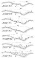
- FIG. 4 there is shown a different surface 11′ which is not cylindrical but complex in curvature.
- the track 13 is shaped to follow the surface along the axis 29 which is the X-axis that the arm 23 follows when the robot member 20 is displaced along the rail 13.
- the probe 26 when the probe 26 is displaced along its Y-axis, it is necessary to move the user arm 28 along the Z-axis and to apply pressure, where necessary, to maintain the probe tip 26′ in contact with the surface 11′, which surface is bent along the Y axis 30.
- the sensor 25 monitors the contact force and the system controls this force adaptatively at a constant predetermined value.
- the probe 26 and the arm 28 could be replaced by a beam measuring device which automatically measures the distance between the surface and a reference point associated with the arm 23 wherein the entire operation and scanning of the surface in the working environment may be done automatically.
- the system as herein described utilizes the intervention of an operator to teach the control circuit the location of the damaged area. This could also be automized if the entire working environmental area has been mapped by the probe.
- the mapping of the entire working environment is bypassed and an operator is utilized to detect an imperfection within the working environment delineated by the X-Y axes.
- the operator positions the probe tip 26′ along a series of coordinate points P1 to P8, as shown in Figure 5, to delineate the damaged area 31 on the surface 11. These points are located outside the damaged area at a distance such that interconnecting lines between the points do not interfere with the damaged area 31.
- the control circuit analyzes these points which are stored in memory, generates a plane surface based on three points using the plane surface as a reference, and calculates a delineated polygonal contour by projecting the points onto this plane along the normal to the plane, as illustrated in Figure 6.
- the control circuit also determines parallel trajectory or passages of a working tool within the plane area delineated by the polygonal contour.
- This computed planar reference surface (generated by three selected ones of the coordinate points) is a curved surface due to the curvature of the track and trajectory of the robot thereon between the selected points.
- this calculated curved surface does not match identically the real surface due to the fact that the track curvature is not absolutely identical to the curvature of the area within the polygonal contour. If for a given application the error is too large, the tool position must be corrected adaptively along the trajectory using such means as arc length control for welding or force feedback control for grinding; in other words the robot monitors some tool parameters and automatically adjusts the tool position relative to the working surface.
- the operator may also select additional coordinate points within the polygonal contoured area or segment the polygonal contoured area into sub-areas so that the work may be performed in two or more phases.
- the distance between each pass, as illustrated at 32 in Figure 7, is programmed by the operator on a command keyboard 56 (see Fig. 11) and the direction of travel of the tool can also be programmed automatically or by the operator as the control circuit knows all of the coordinate points along the polygonal contour which has been segmented.
- the operator selects additional coordinate points within the polygonal contoured area and the control system calculates a bicubic surface which best fits those points, instead of the planar surface. This approach minimizes the error between said calculated surface and said real surface.
- the surface is automatically sampled by a robot arm mounted sensor and a map of the working environment is generated based on collection of points homogeneously distributed about this surface. Bicubic interpolation between the points is performed to provide a full representation of the working environment. The final profile required after completion of the repair is also calculated by bicubic interpolation from the undamaged area.
- the control system calculates tool trajectories on said calculated surface, and the sequence and number of passes are automatically determined based on the knowledge of said final profile.
- FIG. 8A to 8M, 9A to 9C and Figure 10 there is shown a simplified block diagram illustrating the working environment generally at 32a delineated by the X and Y trajectory of the contact probe, and in which is located the damaged area 31 to be repaired.
- Associated with the working arm 23 is one or more working tools, and herein three working tools, a gouging tool 33 which is a welding torch (not shown), a grinding tool 34 and a welding tool 35.
- the working end 23 ⁇ of the working arm 23 is provided with a quick connector (not shown) and illustrated by a point 36 which is engageable with quick connectors 37, also illustrated by a point provided on each of the working tools 33 to 35.
- the handle 28 is also herein schematically illustrated and it is also provided with a connector 38 to interconnect with the connector point 36.
- the robot knows precisely the location of these connecting points and is displaced to engage a working tool, effect a work function and replace it to its initial position, and thereafter engage further tools to effect a work operation.
- Figure 9A illustrates the curved surface 11 on which there is located three damaged areas 31.
- the polygonal coordinates of each of those areas are determined, as above described, and the computer calculates a series of passes 39 for the gouging machine 33 to follow to effect the repair of the three damaged areas 31.
- the gouging torch is engaged and gouges the surfaces to the profile as shown in Figure 9C.
- Figure 9A to 9C illustrates the gouging of the damaged cavitated area 31. After the area has been gouged, the working arm then returns the gouging tool 33 to its location and engages the soldering tool 35 to deposit molten metal 31′ within the cavity 31.
- soldering tool effects successive passes to deposit successive layers of solder material 31′ until the entire cavity has been filled.
- the control circuit has predetermined the amount of weld metal to be deposited in the cavity, as it has knowledge of the entire surface area of the working environment, and thus knows the resulting surface profile 40 which should extend over the cavity by interpolation between the undamaged surface.
- weld metal is built up to and beyond this profile 40, and after this operation is effected the working arm then picks up the grinding tool 34 and grinds the top surface to bring it into conformity with the profile 40.
- the grinding operation is illustrated in Figures 8K to 8M.
- FIG. 12A and 12B there is shown a typical construction of the grinding tool 34.
- the tool herein illustrated is a commercial electric or air-powered grinder driving a grinding disc 41.
- the disc is mounted on a suspension mechanism 42 which is controlled by a force sensor 43 to control the grinding.
- Figure 13 illustrates a typical construction of the welding torch 35. It is secured to a linkage 44 to displace the torch along a 90° axis 45. A further linkage 46 displaces the torch 35 along a further 90° axis 47 transverse to the axis 45. The center of rotation of each axis is close to the tip of the welding torch, thus minimizing the translation of the tool end point during any angular adjustment.
- FIG 11 is a block diagram illustrating the entire control system associated with the robotic member 20 of the present invention.
- the control circuit is based on an Intel System 310 Computer with a multi-tasking real time operating system (iRMX86).
- the approach taken to process control is based on a distributed mode of operation using the BITBUS interconnect from Intel.
- the BITBUS 50 is a microcontroller with its own operating system to accomplish a precise task, i.e., for sensor data acquisition and processing, electrode position and feed rate control for the gouging process, adjustment of parameter settings on the welding power supply 51, etc.
- These distributed tasks run continuously and independently of any task running under the operating system of the central computer.
- Communication to the BITBUS network 50 is handled in a master/slave arrangement of circuits 52 associated with the support equipment.
- the robot member 20 is operated by a control unit 53 and motor control circuits 54 connected to the robot member 20 through a power isolated circuit 55.
- a keyboard 56 and a local pendant 58 are associated with the BITBUS microcontroller to provide an interface with an operator. It is not necessary to describe the details of the control circuit as it utilizes off-the-shelf equipment well known to a person skilled in the art, and the arrangement thereof has been clearly illustrated and described.
- the track 13 is shaped to be supported parallel to a curved or flat surface 11 and the robot member 20 together with its working arm 23 and sensor 25 are displaced along the track 13 during operation.
- the working arm and the sensing probe 24 associated therewith are displaced along X and Y coordinates delineating a working environment for the apparatus.
- the sensor tip is displaced in contact with the surface producing signals to the computer of the X, Y and Z coordinates. Any damaged area within the working environment is detected, either automatically or visually by the operator, and a series of coordinate points about the damaged area are selected and stored within the computer.
- the computer calculates the coordinates of a polygonal contour between the points and about the damaged area with reference to a reference plane.
- the work procedure is planned by the computer and the proper tools are selected to effect a gouging, filling and grinding operation to repair the damaged area. It is pointed out that the entire operation is effected in situ so that the operator can maintain a distance from the working tools during work cycles away from any danger.
- the apparatus may be utilized on flat surfaces and may be used to repair all types of damages and imperfections therein.
- the surface may be formed of materials other than metal, such as plastics, and various other tools may be associated with the robotic working arm.
- the entire operation can be automated without the intervention of an operator during the gathering of information on the delineated area and the working cycle of the robotic arm. The only intervention that may be required by an operator is the connection of the track on the object to be investigated and repaired.
Landscapes
- Engineering & Computer Science (AREA)
- Physics & Mathematics (AREA)
- General Physics & Mathematics (AREA)
- Automation & Control Theory (AREA)
- Optics & Photonics (AREA)
- Mechanical Engineering (AREA)
- Manipulator (AREA)
- Finish Polishing, Edge Sharpening, And Grinding By Specific Grinding Devices (AREA)
- Electrical Discharge Machining, Electrochemical Machining, And Combined Machining (AREA)
- Length Measuring Devices With Unspecified Measuring Means (AREA)
- Measurement Of Length, Angles, Or The Like Using Electric Or Magnetic Means (AREA)
- Machine Tool Sensing Apparatuses (AREA)
- Image Processing (AREA)
Claims (31)
- Vorrichtung zum automatischen Erfassen der Beschaffenheit eines Oberflächenbereiches eines Gegenstandes und zum Ausführen einer Arbeitsfunktion daran, welche Vorrichtung eine Laufbahn (13), die relativ zur Oberfläche (11) anschließbar ist, ein motorbetätigtes Roboterelement (20), das mit der Laufbahn (13) verbindbar ist, welches Roboterelement ein mit einem Motorantrieb versehenes Element aufweist, das mit Laufbahnkopplungseinrichtungen versehen ist, die mit der Laufbahn in Eingriff stehen, um das Roboterelement in einem bestimmten Maß und einer bestimmten Position längs der Laufbahn zu versetzen, einen Arbeitsarm (23), der versetzbar mit dem Roboterelement (20) gekoppelt ist, welcher Arbeitsarm ein oder mehrere Arbeitswerkzeuge (24) aufweist, die daran anschließbar sind, eine Steuerschaltung (27), die dem Roboterelement (20) zugeordnet ist, um dieses zu versetzen und den Arbeitsarm und das Arbeitswerkzeug zu betreiben, und einen Sensor (25) umfaßt, der mit dem Arbeitsarm (23) verbunden ist und eine Sonde (26) aufweist, um eine Strecke, die längs einer Normalen auf die Oberfläche oder eine Oberfläche gemessen wird, zu erfassen, die durch die Steuerschaltung (27) berechnet als repräsentativ für diese Fläche in einer skizzierten Arbeitsumgebung des Roboterelementes (20) und des Arbeitsarmes (23) angenommen wird, welcher Sensor (25) Informationsdaten der X-, Y- und Z-Koordinaten der Steuerschaltung (27) zuführt, um die Geometrie der Oberfläche der Arbeitsumgebung und den Umriß der Bereiche in der Arbeitsumgebung zu bestimmen, an denen Arbeitsvorgänge durch das eine oder die mehreren Arbeitswerkzeuge (24) auszuführen sind.
- Vorrichtung nach Anspruch 1, bei der der Arbeitsarm (23) längs der Y-Achse versetzbar ist, die quer zur X-Achse der Versetzung des Roboterelementes (20) verläuft, wobei der Sensor (25) eine Meßspitze aufweist, die zur Oberfläche gerichtet ist, um Informationssignale auf der Z-Achse bezüglich einer Reihe von Koordinatenpunkten über einen Bereich (31) zu liefern, der eine Bearbeitung benötigt, damit die Steuerschaltung (27) unter Verwendung der X-, Y- und Z-Signale den Umriß und die Form des Bereiches (31) bestimmen kann, der eine Bearbeitung benötigt.
- Vorrichtung nach Anspruch 2, bei der die Oberfläche (11) eine gekrümmte Metallfläche ist, wobei die Laufbahn (13) so gebogen ist, daß sie mit der Krümmung der Oberfläche konform geht.
- Vorrichtung nach Anspruch 3, bei der die gekrümmte Metallfläche (11) ein Oberflächenteil eines hydraulischen Turbinenläufers einer Stromerzeugungsturbine ist, wobei die Laufbahn (13) mit der Oberfläche verbunden ist, um an Ort und Stelle beschädigte Bereiche oder Fehler in dem Oberflächenteil zu reparieren.
- Vorrichtung nach Anspruch 4, bei der die Meßspitze ein Streckenmeßstrahl ist, der die Strecke zwischen dem Sensor (25) und der Oberfläche (11) in der skizzierten Arbeitsumgebung erfaßt.
- Vorrichtung nach Anspruch 2, bei der die Meßspitze eine Kontaktsonde (26) ist, die in einen Kontakt mit der Oberfläche versetzt wird, um die Strecke zwischen dem Bezugspunkt des Armes (23) und der Oberfläche (11) in der skizzierten Arbeitsumgebung zu erfassen, wobei der Arm einen verschiebbaren Anschluß hat, damit die Sonde (26) längs der Z-Achse versetzt werden kann, und der Sensor (25) einen Dehnungsmesser zum Messen dieser Versetzung aufweist.
- Vorrichtung nach Anspruch 2, bei der die Steuerschaltung (27) eine Programmfunktion hat, um die Bahn des Werkzeuges (24) über den Bereichen, die zu bearbeiten sind, und die Anzahl der Durchgänge des Arbeitswerkzeuges in diesen Bereichen zu bestimmen.
- Vorrichtung nach Anspruch 7, bei der ein oder mehrere Arbeitswerkzeuge (33, 34, 35) vorgesehen sind, die an bestimmten Stellen relativ zum Roboterelement (20) angeordnet sind, wobei die Arbeitswerkzeuge automatisch gewählt und durch den Arbeitsarm zur Ausfuhrüng von gesteuerten Arbeitsfunktionen erfaßt werden.
- Vorrichtung nach Anspruch 8, bei der die Oberfläche (11) eine Metallfläche ist, und ein Bogenaushöhlwerkzeug (33), ein Schweißwerkzeug (25) und ein Schleifwerkzeug (34) vorgesehen sind, durch die die beschädigten Bereiche ausgehöhlt, mit Schweißmaterial bis wenigstens zum Oberflächenprofil der Metallfläche in der Arbeitsumgebung gefüllt und die gefüllten Bereiche so geschliffen werden, daß sie mit der Oberfläche der Arbeitsumgebung (32a) fluchten.
- Vorrichtung nach Anspruch 6, bei der der Arbeitsarm (23) mit einer Griffeinrichtung (28) versehen ist, die mit einem Kraftsensor (55) gekoppelt ist, damit eine Arbeitsperson diesen so versetzen kann, daß er den Meßpunkt relativ zu Koordinatenpunkten über einen gewählten beschädigten Bereich in der Arbeitsumgebung (32a) ausrichtet, um dadurch einen polygonalen Umriß des beschädigten Bereiches (31) zu bilden, in dem eine gesteuerte Arbeitsfunktion auszuführen ist.
- Vorrichtung nach Anspruch 10, bei der die Steuerschaltung (27) eine selbstlernende Programmfunktion hat und das mit einem Motorantrieb versehene Element so betreibt, daß das Roboterelement (20) längs der Laufbahn (13) versetzt wird, um die Geometrie der Laufbahn zu bestimmen, so daß die Steuerschaltung (27) einen Werkzeugendbezugspunkt eines Arbeitswerkzeuges zu einem cartesischen Raum in Bezug setzen kann.
- Vorrichtung nach Anspruch 3, bei der die Laufbahn (13) längs einer geraden Achse verläuft.
- Vorrichtung nach Anspruch 3, bei der die Oberfläche (11) eine Metallfläche ist und die Laufbahn (13) in einer gewünschten Form in Abhängigkeit von der Form der Oberfläche profiliert ist, und die Laufbahn (13) an einem Bahnhalter (14) befestigt ist, der von der Oberfläche durch einstellbare Haltefüße (15) abgehoben gehalten ist, welche Haltefüße unbeweglich an der Oberfläche (11) befestigt sind.
- Vorrichtung nach Anspruch 13, bei der die einstellbaren Haltefüße (15) schwenkbar mit dem Bahnhalter (14) verbunden sind, wobei die Füße in der Länge einstellbar sind, um den Bahnhalter (14) auf einer gewünschten Höhe relativ zur Oberfläche (11) zu positionieren, damit der Arbeitsarm (23) dazu parallel gehalten ist.
- Verfahren zum automatischen Erfassen der Beschaffenheit eines Oberflächenbereiches und zum Ausführen einer Arbeitsfunktion daran, welches Verfahren die Schritte umfaßt:(i) Anschließen einer Haltelaufbahn (13) über einem Teil des Oberflächenbereiches, welche Laufbahn (13) ein motorbetätigtes Roboterelement (20), das damit verbunden und mit einem Arbeitsarm (23) versehen ist, der verschiebbar damit gekoppelt ist, einen Sensor (25), der mit dem Arbeitsarm verbunden ist, und eine Steuerschaltung (27) aufweist, die dem Roboterelement (20) zugeordnet ist,(ii) Versetzen des Roboterelementes (20) und des Arbeitsarmes (23) längs der X- und Y-Koordinaten jeweils, um eine Arbeitsumgebung (32a) neben der Laufbahn (13) zu skizzieren, während der Abstand zwischen der Oberfläche (11) und einem Bezugspunkt des Armes (23) längs der Z-Koordinaten erfaßt und Informationsdatensignale der X-, Y- und Z-Koordinaten erzeugt werden, um Signale zu speichern, die die Oberflächenbeschaffenheit der Arbeitsumgebung angeben,(iii) Ermitteln von irregulären Oberflächenbereichen (31) innerhalb der Arbeitsumgebung,(iv) Bestimmen einer Reihe von Koordinatenpunkten über einen gewählten irregulären Oberflächenbereich, damit die Steuerschaltung (27) eine Bezugsebene auf der Grundlage von drei dieser Punkte bestimmen und die Projektion aller Punkte auf diese Ebene finden kann, um dadurch den polygonalen Umriß in dieser Ebene zu bestimmen und Informationssignale zu speichern, die dafür repräsentativ sind,(v) Wählen und Anschließen eines Werkzeuges (24) an den Arbeitsarm (23),(vi) Ausführen einer Arbeitsfunktion mit dem Werkzeug in dem Bereich mit polygonalem Umriß.
- Verfahren nach Anspruch 15, bei dem der Schritt (iv) weiterhin das Bestimmen einer Reihe von Koordinatenpunkten sowohl innerhalb als auch außerhalb des irregulären Oberflächenbereiches umfaßt, damit die Steuerschaltung (27) die irreguläre Oberfläche modelieren und das endgültige Profil finden kann, das nach Abschluß der Arbeitsfunktion erforderlich ist.
- Verfahren nach Anspruch 15, bei dem weiterhin der Schritt der Positionierung von zwei oder mehr Werkzeugen (33, 34, 35) an bestimmten Stellen bezüglich der Laufbahn (13) und der automatischen Ineingriffnahme der Werkzeuge in einer bestimmten Reihenfolge vorgesehen ist, um eine Reihe von Arbeitsfunktionen in dem Bereich (31) mit polygonalem Umriß auszuführen.
- Verfahren nach Anspruch 17, bei dem weiterhin der Schritt der Selbstprogrammierung der Steuerschaltung (27) vorgesehen ist, um die Arbeitefunktionen dadurch auszuführen, daß die Informationssignale analysiert werden, um die Beschaffenheit der irregulären Oberflächenbereiche zu ermitteln.
- Verfahren nach Anspruch 15, bei dem der Schritt (ii) das von Hand erfolgende Anordnen eines Meßfühlers (26), der mit dem Sensor (25) verbunden ist, in Kontakt mit der Arbeitsumgebung längs der X-, Y- und Z-Achse umfaßt, um deren Oberflächenbeschaffenheit zu bestimmen.
- Verfahren nach Anspruch 19, bei dem der Schritt (iii) das optische Erfassen der irregulären Oberflächenbereiche umfaßt.
- Verfahren nach Anspruch 20, bei dem der Schritt (iv) das von Hand erfolgende Anordnen der Sonde (26) an einer Reihe von Punkten über einen oder mehrere irreguläre Bereiche umfaßt, um Informationssignale der Steuerschaltung (27) zum automatischen Skizzieren eines polygonalen Umrisses zu liefern.
- Verfahren nach Anspruch 15, bei dem die Schritte (v) und (vi) der Reihe nach mit einem Aushöhlwerkzeug (33), einem Schweißwerkzeug (35) und einem Schleifwerkzeug (34) ausgeführt werden, um einen ausgehöhlten beschädigten irregulären Bereich zu reinigen, ihn mit Schweißmaterial zu füllen und so zu schleifen, daß er mit der Oberflächenform der skizzierten Arbeitsumgebung fluchtet.
- Verfahren nach Anspruch 22, bei dem das Aushöhlwerkzeug (33) zum Aushöhlen des Metalls in der Fläche mit polygonalem Umriß gesteuert wird, wobei das Ausöhlwerkzeug automatisch gesteuert und dann abgeschaltet wird, wenn die ausgehöhlte Oberfläche glatt geworden ist.
- Verfahren nach Anspruch 22, bei dem das Aushöhlen das Entfernen einer Vielzahl von aufeinanderfolgenden Metallschichten umfaßt, während das Aushöhlwerkzeug (33) in einem im wesentlichen konstanten Werkstückabstand gehalten wird, indem der Aushöhlstrom überwacht wird, der durch eine Elektrode des Werkzeugs fließt.
- Verfahren nach Anspruch 23, bei dem der weitere Schritt des Schleifens des ausgehöhlten polygonalen Bereiches vorgesehen ist, um ihn vor dem Füllen mit dem Schweißmaterial zu reinigen und somit für einen für das Schweißen angemessen vorbereiteten Hohlraum zu sorgen.
- Verfahren nach Anspruch 22, bei dem der Schritt der Füllung des vorbereiteten Hohlraums das Aufbringen einer Vielzahl von aufeinanderfolgenden Schichten des Schweißmaterials (31') im Hohlraumbereich und das Halten des Schweißwerkzeuges (35) in einem im wesentlichen konstanten Werkstückabstand umfaßt, indem der Schweißstrom und die Schweißspannung überwacht werden.
- Verfahren nach Anspruch 22, bei dem der Schleifschritt das Anwenden einer Vielzahl von aufeinanderfolgenden Schleifdurchgängen über der Schweißstelle umfaßt, während eine gesteuerte Schleifkraft beibehalten wird, indem ein Dehnungsmesser im Sensor (25) überwacht wird.
- Verfahren nach Anspruch 22, bei dem weiterhin der Schritt der Erfassung des Oberflächenbereiches des polygonalen beschädigten Bereiches zwischen den Schritten der Aushöhlung, des Schweißens und des Schleifens vorgesehen ist.
- Verfahren nach Anspruch 15, bei dem der Schritt (i) das Vorsehen eines Bahnhalterahmens (14) am Oberflächenbereich und das Einstellen seiner Höhe und das Anchließen der Haltelaufbahn (13) am Halterahmen umfaßt.
- Verfahren nach Anspruch 15, bei dem die Schritte (ii) und (iii) dadurch bewirkt werden, daß ein mit einem Motorantrieb versehenes Element betätigt wird, das mit einer Kopplungseinrichtung für die Laufbahn (13) und einer Versetzungseinrichtung für den Arbeitsarm (23) versehen ist.
- Verfahren nach Anspruch 15, bei dem die Schritte (ii) und (vi) automatisch durch die Steuerschaltung (27) bewirkt werden.
Applications Claiming Priority (2)
| Application Number | Priority Date | Filing Date | Title |
|---|---|---|---|
| US273075 | 1988-11-18 | ||
| US07/273,075 US4959523A (en) | 1988-11-18 | 1988-11-18 | Method and apparatus for automatically sensing the configuration of a surface area and effecting a work function thereon |
Publications (3)
| Publication Number | Publication Date |
|---|---|
| EP0369891A2 EP0369891A2 (de) | 1990-05-23 |
| EP0369891A3 EP0369891A3 (de) | 1991-09-04 |
| EP0369891B1 true EP0369891B1 (de) | 1994-10-05 |
Family
ID=23042442
Family Applications (1)
| Application Number | Title | Priority Date | Filing Date |
|---|---|---|---|
| EP89403177A Expired - Lifetime EP0369891B1 (de) | 1988-11-18 | 1989-11-17 | Verfahren und Gerät zum automatischen Abtasten eines Gebietes einer Oberfläche und zum Ausführen einer Bearbeitungsfunktion darauf |
Country Status (8)
| Country | Link |
|---|---|
| US (1) | US4959523A (de) |
| EP (1) | EP0369891B1 (de) |
| JP (1) | JPH02237726A (de) |
| AT (1) | ATE112642T1 (de) |
| BR (1) | BR8905820A (de) |
| CA (1) | CA2002513C (de) |
| DE (1) | DE68918670T2 (de) |
| MX (1) | MX165384B (de) |
Families Citing this family (54)
| Publication number | Priority date | Publication date | Assignee | Title |
|---|---|---|---|---|
| US5148000A (en) * | 1990-01-04 | 1992-09-15 | Crc-Evans Pipeline International, Inc. | Distributed processing control system for automatic welding operation |
| ES2120414T3 (es) * | 1991-01-21 | 1998-11-01 | Sulzer Hydro Ag | Metodo de fabricacion de piezas metalicas por un aparato de soldadura, y aparato para su realizacion. |
| WO1993020493A1 (en) * | 1992-04-03 | 1993-10-14 | Foster-Miller, Inc. | Method and apparatus for obtaining coordinates describing three-dimensional objects of complex and unique geometry using a sampling probe |
| US5442565A (en) * | 1992-05-01 | 1995-08-15 | Seamx | Autonomous selective cutting method and apparatus |
| US5811755A (en) * | 1996-01-11 | 1998-09-22 | Lockheed Martin Corp. | Weld repair method for aluminum lithium seam |
| US20020005397A1 (en) * | 1998-04-10 | 2002-01-17 | Bong William L. | Modular welding system and method |
| JP3307886B2 (ja) * | 1998-10-16 | 2002-07-24 | 松下電器産業株式会社 | 溶接装置 |
| AT409731B (de) * | 1998-10-16 | 2002-10-25 | Fronius Schweissmasch Prod | Regelvorrichtung für ein schweissgerät |
| US6560513B2 (en) * | 1999-11-19 | 2003-05-06 | Fanuc Robotics North America | Robotic system with teach pendant |
| FR2806337B1 (fr) * | 2000-03-15 | 2002-05-31 | Joseph Sauron Materiel Ind | Procede et automate de soudage a l'arc utilisant des fils fourres |
| JP2001259839A (ja) * | 2000-03-22 | 2001-09-25 | Matsushita Electric Ind Co Ltd | アーク溶接装置 |
| US6376801B1 (en) * | 2000-10-12 | 2002-04-23 | General Electric Company | Gas turbine component refurbishment apparatus and repair method |
| AT413954B (de) * | 2000-11-02 | 2006-07-15 | Fronius Int Gmbh | Erfassungselement für ein schweissgerät |
| US6492618B1 (en) | 2000-11-02 | 2002-12-10 | Tri Tool Inc. | Automatic weld head alignment and guidance system and method |
| ITTO20010294A1 (it) * | 2001-03-29 | 2002-09-29 | Parmaprogetti Srl | Dispositivo per il posizionamento di un organo operatore, ed apparecchiatura saldatrice che ne fa uso. |
| US6944925B2 (en) * | 2001-06-13 | 2005-09-20 | Ttx Company | Articulated connector reconditioning process and apparatuses |
| KR100593535B1 (ko) * | 2001-09-03 | 2006-06-28 | 현대중공업 주식회사 | 각도별 용접조건 자동제어 및 위빙 모션 구현이 가능한자기 진단형 용접 캐리지 제어기 |
| US6548783B1 (en) * | 2001-10-03 | 2003-04-15 | General Electric Company | Apparatus for electric arc overlay welding |
| WO2006057042A1 (ja) * | 2004-11-26 | 2006-06-01 | Shishiai-Kabushikigaisha | 熱媒体組成物 |
| US8895895B2 (en) * | 2007-02-27 | 2014-11-25 | Illinois Tool Works, Inc. | System and method for protecting a welding-type system from strain |
| US9292016B2 (en) | 2007-10-26 | 2016-03-22 | Ariel Andre Waitzman | Automated welding of moulds and stamping tools |
| US9776274B2 (en) | 2007-10-26 | 2017-10-03 | Ariel Andre Waitzman | Automated welding of moulds and stamping tools |
| US8367962B2 (en) | 2007-10-26 | 2013-02-05 | Ariel Andre Waitzman | Automated welding of moulds and stamping tools |
| JP4950018B2 (ja) * | 2007-12-25 | 2012-06-13 | アルプス電気株式会社 | 座標入力装置 |
| US20100122973A1 (en) * | 2008-11-20 | 2010-05-20 | General Electric Company | Welding process |
| WO2011102945A2 (en) * | 2010-02-19 | 2011-08-25 | Dresser-Rand Company | Welded structural flats on cases to eliminate nozzles |
| US8595930B2 (en) * | 2010-03-24 | 2013-12-03 | Dresser-Rand Company | Press-fitting corrosion resistant liners in nozzles and casings |
| FR2970195B1 (fr) * | 2011-01-06 | 2014-01-31 | Ctf France | Automate pour la maintenance de rails et procede de mise en oeuvre |
| GB201103235D0 (en) * | 2011-02-25 | 2011-04-13 | Mirage Machines Ltd | Apparatus,method,system and computer program for machining a workpiece |
| CA2845752C (en) * | 2011-08-18 | 2016-07-12 | Victor Equipment Company | Air -carbon arc system for detecting and/or reducing irregularities in a work piece surface and method of using the same |
| US9052183B2 (en) | 2012-01-25 | 2015-06-09 | Ttx Company | Application of wear plate to articulated connector load bearing bottom surface |
| US9126287B2 (en) * | 2012-03-12 | 2015-09-08 | Siemens Energy, Inc. | Advanced pass progression for build-up welding |
| US8720526B1 (en) | 2012-11-13 | 2014-05-13 | Siemens Energy, Inc. | Process for forming a long gas turbine engine blade having a main wall with a thin portion near a tip |
| CN103846769A (zh) * | 2012-12-06 | 2014-06-11 | 青岛海尔模具有限公司 | 机器人辅助自适应曲面自动抛光系统 |
| US10480862B2 (en) | 2013-05-23 | 2019-11-19 | Crc-Evans Pipeline International, Inc. | Systems and methods for use in welding pipe segments of a pipeline |
| US11767934B2 (en) | 2013-05-23 | 2023-09-26 | Crc-Evans Pipeline International, Inc. | Internally welded pipes |
| US10040141B2 (en) | 2013-05-23 | 2018-08-07 | Crc-Evans Pipeline International, Inc. | Laser controlled internal welding machine for a pipeline |
| US10695876B2 (en) | 2013-05-23 | 2020-06-30 | Crc-Evans Pipeline International, Inc. | Self-powered welding systems and methods |
| US10589371B2 (en) | 2013-05-23 | 2020-03-17 | Crc-Evans Pipeline International, Inc. | Rotating welding system and methods |
| US9821415B2 (en) | 2014-03-28 | 2017-11-21 | Crc-Evans Pipeline International, Inc. | Internal pipeline cooler |
| CA2948393A1 (fr) * | 2014-07-29 | 2016-02-04 | Hydro-Quebec | Systeme et methode de traitement thermique robotise par chauffage a induction |
| RU2695694C2 (ru) | 2014-08-29 | 2019-07-25 | СиАрСи-ЭВАНС ПАЙПЛАЙН ИНТЕРНЭШНЛ ИНК. | Способ и система сварки |
| US10065318B2 (en) | 2014-09-15 | 2018-09-04 | The Boeing Company | Methods and systems of repairing a structure |
| US10286553B2 (en) | 2014-09-15 | 2019-05-14 | The Boeing Company | Methods and systems for automatically inspecting an object |
| EP3045394B1 (de) * | 2015-01-16 | 2020-05-27 | The Boeing Company | Verfahren und system zur reparatur einer struktur |
| AU2016250430B2 (en) * | 2015-10-30 | 2021-07-08 | Ian David McCowat | Method and Apparatus for Refurbishing Shovel Lips |
| US11458571B2 (en) | 2016-07-01 | 2022-10-04 | Crc-Evans Pipeline International, Inc. | Systems and methods for use in welding pipe segments of a pipeline |
| US10226944B2 (en) | 2016-08-30 | 2019-03-12 | The Boeing Company | Adaptable surface treatment repair system |
| US10668577B2 (en) | 2016-09-01 | 2020-06-02 | Crc-Evans Pipeline International Inc. | Cooling ring |
| FR3061053A1 (fr) * | 2016-12-23 | 2018-06-29 | 9349 3039 Quebec Inc | Appareil de reconditionnement de piece lourde et procede |
| US10954001B2 (en) | 2017-02-23 | 2021-03-23 | The Boeing Company | Hanging clamped supports for aircraft |
| US10286460B2 (en) * | 2017-04-07 | 2019-05-14 | Robert J. Murphy | Single-pass, single-radial layer, circumferential-progression fill-welding system, apparatus and method for refurbishing railway and other transit rails |
| CN112139860A (zh) * | 2020-09-22 | 2020-12-29 | 佳奕筱安(上海)机器人科技有限公司 | 基于力控机器人打磨的柔顺轨迹输出方法及其实施装置 |
| CN112917166B (zh) * | 2021-02-04 | 2021-09-07 | 冯剑亮 | 一种机器人脚底板磨纹装置 |
Family Cites Families (11)
| Publication number | Priority date | Publication date | Assignee | Title |
|---|---|---|---|---|
| JPS55125960A (en) * | 1979-03-12 | 1980-09-29 | Sankyo Seiki Mfg Co Ltd | Automatic working device |
| US4283044A (en) * | 1979-03-23 | 1981-08-11 | Mckibbin John R | Apparatus for guiding a tool along a curved path |
| JPS58208807A (ja) * | 1982-05-31 | 1983-12-05 | Nissan Motor Co Ltd | ロボツトのテイ−チング装置 |
| US4531192A (en) * | 1982-09-23 | 1985-07-23 | Crc Welding Systems, Inc. | Apparatus and method for sensing a workpiece with an electrical arc |
| US4596919A (en) * | 1984-08-23 | 1986-06-24 | Sri International | Three-dimensional imaging device |
| US4716271A (en) * | 1984-09-28 | 1987-12-29 | Welding Services, Inc. | Apparatus for positioning a tool with respect to a cylindrical work piece |
| GB8508391D0 (en) * | 1985-03-30 | 1985-05-09 | Ae Plc | Measurement of engineering components |
| JPS62207580A (ja) * | 1986-03-06 | 1987-09-11 | Kobe Steel Ltd | 偏摩耗した太径長尺ロ−ルの溶接補修方法 |
| US4841123A (en) * | 1987-06-17 | 1989-06-20 | Welding Services, Inc. | Automatic welding device |
| IT1211390B (it) * | 1987-10-06 | 1989-10-18 | Dea Spa | Sistema grafico interattivo per la matematizzazione di modelli fisici |
| DE3907624A1 (de) * | 1988-07-08 | 1990-01-11 | Mtu Maintenance Gmbh | Vorrichtung zum auftragsschweissen der schaufelspitzen von turbinen- und kompressor-schaufeln |
-
1988
- 1988-11-18 US US07/273,075 patent/US4959523A/en not_active Expired - Lifetime
-
1989
- 1989-11-08 CA CA002002513A patent/CA2002513C/fr not_active Expired - Lifetime
- 1989-11-16 MX MX018389A patent/MX165384B/es unknown
- 1989-11-17 JP JP1299486A patent/JPH02237726A/ja active Pending
- 1989-11-17 EP EP89403177A patent/EP0369891B1/de not_active Expired - Lifetime
- 1989-11-17 BR BR898905820A patent/BR8905820A/pt not_active IP Right Cessation
- 1989-11-17 DE DE68918670T patent/DE68918670T2/de not_active Expired - Fee Related
- 1989-11-17 AT AT89403177T patent/ATE112642T1/de not_active IP Right Cessation
Also Published As
| Publication number | Publication date |
|---|---|
| ATE112642T1 (de) | 1994-10-15 |
| DE68918670D1 (de) | 1994-11-10 |
| US4959523A (en) | 1990-09-25 |
| EP0369891A3 (de) | 1991-09-04 |
| CA2002513A1 (fr) | 1990-05-18 |
| CA2002513C (fr) | 1994-10-11 |
| MX165384B (es) | 1992-11-06 |
| DE68918670T2 (de) | 1995-05-24 |
| JPH02237726A (ja) | 1990-09-20 |
| EP0369891A2 (de) | 1990-05-23 |
| BR8905820A (pt) | 1990-06-12 |
Similar Documents
| Publication | Publication Date | Title |
|---|---|---|
| EP0369891B1 (de) | Verfahren und Gerät zum automatischen Abtasten eines Gebietes einer Oberfläche und zum Ausführen einer Bearbeitungsfunktion darauf | |
| US7123990B2 (en) | Gap welding process | |
| EP3553282B1 (de) | System und verfahren zur inspektion und/oder reparatur einer oder mehrerer an einem rotor einer gasturbine befestigten schaufeln unter verwendung eines robotersystems | |
| CN107253084B (zh) | 飞机数字化装配中的高效高精机器人自动铣削系统 | |
| US10449619B2 (en) | System for processing a workpiece | |
| US4590578A (en) | Off-line programmable robot | |
| US6021361A (en) | Robot control system | |
| US4642752A (en) | Programmable automatic manipulator system | |
| KR101268918B1 (ko) | 파이프 플랜지 자동 용접 방법 및 장치 | |
| US5347101A (en) | Automatic tracking system for pipeline welding | |
| CN104858748A (zh) | 一种叶片进排气边磨削机器人自动化装备 | |
| US20080173624A1 (en) | Method and apparatus for repairing turbine components | |
| CN106965051A (zh) | 螺旋焊管管端智能修磨设备 | |
| US4042161A (en) | Automatic welding apparatus | |
| EP3130971A1 (de) | Maschinenwerkzeugbahnkompensierung mit vibrationserfassung | |
| EP3630404B1 (de) | Vorrichtung und verfahren zum automatisierten nahtschweissen eines werkstücks, das eine basisplatte mit einem muster von hochstehenden profilen enthält | |
| CN111872850A (zh) | 一种基于焊缝打磨的恒力控制系统 | |
| CN114515924A (zh) | 一种基于焊缝识别的塔脚工件自动焊接系统及方法 | |
| CN111545946B (zh) | 电解铝阳极钢爪高效自动焊接系统及实现方法 | |
| CN115592414A (zh) | 一种用于细长筒类零件的多机器人协同加工装置及方法 | |
| CN212240604U (zh) | 一种基于焊缝打磨的恒力控制装置 | |
| CN117067227A (zh) | 一种机器人智能修边系统 | |
| CN212398554U (zh) | 电解铝阳极钢爪高效自动焊接系统 | |
| JPH03170283A (ja) | ロボット制御装置 | |
| JPS61188095A (ja) | 産業用ロボツトにおける位置制御装置 |
Legal Events
| Date | Code | Title | Description |
|---|---|---|---|
| PUAI | Public reference made under article 153(3) epc to a published international application that has entered the european phase |
Free format text: ORIGINAL CODE: 0009012 |
|
| AK | Designated contracting states |
Kind code of ref document: A2 Designated state(s): AT BE CH DE ES FR GB GR IT LI LU NL SE |
|
| PUAL | Search report despatched |
Free format text: ORIGINAL CODE: 0009013 |
|
| AK | Designated contracting states |
Kind code of ref document: A3 Designated state(s): AT BE CH DE ES FR GB GR IT LI LU NL SE |
|
| 17P | Request for examination filed |
Effective date: 19920226 |
|
| 17Q | First examination report despatched |
Effective date: 19940207 |
|
| GRAA | (expected) grant |
Free format text: ORIGINAL CODE: 0009210 |
|
| AK | Designated contracting states |
Kind code of ref document: B1 Designated state(s): AT BE CH DE ES FR GB GR IT LI LU NL SE |
|
| PG25 | Lapsed in a contracting state [announced via postgrant information from national office to epo] |
Ref country code: NL Effective date: 19941005 Ref country code: LI Effective date: 19941005 Ref country code: GR Free format text: LAPSE BECAUSE OF FAILURE TO SUBMIT A TRANSLATION OF THE DESCRIPTION OR TO PAY THE FEE WITHIN THE PRESCRIBED TIME-LIMIT Effective date: 19941005 Ref country code: ES Free format text: THE PATENT HAS BEEN ANNULLED BY A DECISION OF A NATIONAL AUTHORITY Effective date: 19941005 Ref country code: CH Effective date: 19941005 Ref country code: BE Effective date: 19941005 Ref country code: AT Effective date: 19941005 |
|
| REF | Corresponds to: |
Ref document number: 112642 Country of ref document: AT Date of ref document: 19941015 Kind code of ref document: T |
|
| ITF | It: translation for a ep patent filed | ||
| REF | Corresponds to: |
Ref document number: 68918670 Country of ref document: DE Date of ref document: 19941110 |
|
| PG25 | Lapsed in a contracting state [announced via postgrant information from national office to epo] |
Ref country code: LU Free format text: LAPSE BECAUSE OF NON-PAYMENT OF DUE FEES Effective date: 19941130 |
|
| PG25 | Lapsed in a contracting state [announced via postgrant information from national office to epo] |
Ref country code: SE Effective date: 19950105 |
|
| REG | Reference to a national code |
Ref country code: CH Ref legal event code: PL |
|
| ET | Fr: translation filed | ||
| NLV1 | Nl: lapsed or annulled due to failure to fulfill the requirements of art. 29p and 29m of the patents act | ||
| PLBE | No opposition filed within time limit |
Free format text: ORIGINAL CODE: 0009261 |
|
| STAA | Information on the status of an ep patent application or granted ep patent |
Free format text: STATUS: NO OPPOSITION FILED WITHIN TIME LIMIT |
|
| 26N | No opposition filed | ||
| PGFP | Annual fee paid to national office [announced via postgrant information from national office to epo] |
Ref country code: FR Payment date: 19991018 Year of fee payment: 11 |
|
| PGFP | Annual fee paid to national office [announced via postgrant information from national office to epo] |
Ref country code: DE Payment date: 19991028 Year of fee payment: 11 |
|
| PGFP | Annual fee paid to national office [announced via postgrant information from national office to epo] |
Ref country code: GB Payment date: 19991109 Year of fee payment: 11 |
|
| PG25 | Lapsed in a contracting state [announced via postgrant information from national office to epo] |
Ref country code: GB Free format text: LAPSE BECAUSE OF NON-PAYMENT OF DUE FEES Effective date: 20001117 |
|
| GBPC | Gb: european patent ceased through non-payment of renewal fee |
Effective date: 20001117 |
|
| PG25 | Lapsed in a contracting state [announced via postgrant information from national office to epo] |
Ref country code: FR Free format text: LAPSE BECAUSE OF NON-PAYMENT OF DUE FEES Effective date: 20010731 |
|
| PG25 | Lapsed in a contracting state [announced via postgrant information from national office to epo] |
Ref country code: DE Free format text: LAPSE BECAUSE OF NON-PAYMENT OF DUE FEES Effective date: 20010801 |
|
| REG | Reference to a national code |
Ref country code: FR Ref legal event code: ST |
|
| PG25 | Lapsed in a contracting state [announced via postgrant information from national office to epo] |
Ref country code: IT Free format text: LAPSE BECAUSE OF NON-PAYMENT OF DUE FEES Effective date: 20051117 |