EP0368961B1 - Umkehrschaltvorrichtung für gleichstrom - Google Patents
Umkehrschaltvorrichtung für gleichstrom Download PDFInfo
- Publication number
- EP0368961B1 EP0368961B1 EP89905359A EP89905359A EP0368961B1 EP 0368961 B1 EP0368961 B1 EP 0368961B1 EP 89905359 A EP89905359 A EP 89905359A EP 89905359 A EP89905359 A EP 89905359A EP 0368961 B1 EP0368961 B1 EP 0368961B1
- Authority
- EP
- European Patent Office
- Prior art keywords
- switch
- housing
- trigger
- assembly
- compact
- Prior art date
- Legal status (The legal status is an assumption and is not a legal conclusion. Google has not performed a legal analysis and makes no representation as to the accuracy of the status listed.)
- Expired - Lifetime
Links
- 238000009413 insulation Methods 0.000 claims abstract description 29
- 230000010355 oscillation Effects 0.000 claims description 2
- 230000003534 oscillatory effect Effects 0.000 claims description 2
- 230000007246 mechanism Effects 0.000 description 7
- 230000006835 compression Effects 0.000 description 5
- 238000007906 compression Methods 0.000 description 5
- 230000004048 modification Effects 0.000 description 3
- 238000012986 modification Methods 0.000 description 3
- 238000005192 partition Methods 0.000 description 3
- 230000002441 reversible effect Effects 0.000 description 3
- 125000006850 spacer group Chemical group 0.000 description 3
- RYGMFSIKBFXOCR-UHFFFAOYSA-N Copper Chemical compound [Cu] RYGMFSIKBFXOCR-UHFFFAOYSA-N 0.000 description 2
- 230000004075 alteration Effects 0.000 description 2
- 238000010276 construction Methods 0.000 description 2
- 229910052802 copper Inorganic materials 0.000 description 2
- 239000010949 copper Substances 0.000 description 2
- WABPQHHGFIMREM-UHFFFAOYSA-N lead(0) Chemical compound [Pb] WABPQHHGFIMREM-UHFFFAOYSA-N 0.000 description 2
- 238000004519 manufacturing process Methods 0.000 description 2
- 230000007935 neutral effect Effects 0.000 description 2
- 230000004913 activation Effects 0.000 description 1
- 239000004020 conductor Substances 0.000 description 1
- 238000011161 development Methods 0.000 description 1
- 230000018109 developmental process Effects 0.000 description 1
- 238000009434 installation Methods 0.000 description 1
- 239000000463 material Substances 0.000 description 1
- 239000012811 non-conductive material Substances 0.000 description 1
Images


Classifications
-
- H—ELECTRICITY
- H01—ELECTRIC ELEMENTS
- H01H—ELECTRIC SWITCHES; RELAYS; SELECTORS; EMERGENCY PROTECTIVE DEVICES
- H01H19/00—Switches operated by an operating part which is rotatable about a longitudinal axis thereof and which is acted upon directly by a solid body external to the switch, e.g. by a hand
- H01H19/02—Details
- H01H19/10—Movable parts; Contacts mounted thereon
-
- H—ELECTRICITY
- H01—ELECTRIC ELEMENTS
- H01H—ELECTRIC SWITCHES; RELAYS; SELECTORS; EMERGENCY PROTECTIVE DEVICES
- H01H9/00—Details of switching devices, not covered by groups H01H1/00 - H01H7/00
- H01H9/02—Bases, casings, or covers
- H01H9/06—Casing of switch constituted by a handle serving a purpose other than the actuation of the switch, e.g. by the handle of a vacuum cleaner
- H01H9/063—Casing of switch constituted by a handle serving a purpose other than the actuation of the switch, e.g. by the handle of a vacuum cleaner enclosing a reversing switch
-
- H—ELECTRICITY
- H01—ELECTRIC ELEMENTS
- H01H—ELECTRIC SWITCHES; RELAYS; SELECTORS; EMERGENCY PROTECTIVE DEVICES
- H01H9/00—Details of switching devices, not covered by groups H01H1/00 - H01H7/00
- H01H9/52—Cooling of switch parts
Definitions
- the present invention relates to electric switches, and more particularly to a compact electrical reversing switch for a power tool. utensil or other motor driven device.
- the invention is particularly applicable to a compact D.C. reversing switch for reversing the direction of rotation of an electric motor of a hand-held, cordless power tool and will be described with particular reference thereto, although it will be understood that the present invention finds advantageous application in other switching operations.
- the present invention relates generally to a compact reversing switch of the type disclosed in U.S. Letters Patent No. 3,691,322, issued September 12, 1972 to Benjamin H. Matthews, entitled "Reversing Switch".
- the patent discloses a two position reversing switch comprised of a relatively stationary body segment having a plurality of stationary contacts mounted thereon and a rotary segment having a plurality of contacts mounted thereon for rotation therewith.
- the rotary segment is rotatable about an axis through the stationary body segment for moving the contact elements into several operative positions wherein the contacts of the rotary segment engage several of the contacts of the stationary body segment in a predetermined pattern to conductively bridge several of the stationary contacts.
- a lever means is mounted on the switch housing and coacts with the rotary segment for moving the rotary contacts to one or the other of its operative positions.
- the disclosed switch has proved to be extremely dependable when used in reversible hand-held power tools operable on A.C. power.
- Recent developments in rechargeable batteries have led to a greater demand for cordless power tools which are operable by rechargeable D.C. battery packs.
- these rechargeable D.C. battery packs operate at relatively low voltage/high current levels.
- the aforementioned compact reversing switch, and others like it which were suitable for use with high voltage/low current A.C. power, simply do not have the capacity to handle the higher amperage of these new D.C. battery packs.
- One problem is that such switches include relatively small, delicate contact members which produce substantial resistance to current flow.
- a typical switch known heretofore would exhibit a resistance of over 200 milliohm thereacross. Such resistance reduces current flow, and would generate substantial heat within the switch if used with a high-amperage D.C. power source. Moreover, with high amperage, arcing between the contacts also becomes a substantial problem for prior switches.
- U.S. Patent 3,703,646 discloses a portable electric tool having an on-off trigger switch and a motor reversing switch. The two switches are interlocked in such a manner as to prevent the tool from being reversed while it is in operation.
- the reversing switch is of the type having a pivoted actuating element which can be moved between either of two lateral "on" positions, one driving the motor in a forward direction and the other driving it in the reverse direction.
- U.S. Patent 4,678,871 discloses a reversing switch for use in a hand tool.
- the switch has an actuator which is pivotally connected to an insulating mounting support which also has two transfer terminals, one connected to each of two terminals of the battery, and a contact carrier which is rotatably connected to the support and coupled to the actuator in order to be rotated by the pivoting of the actuator. Pivoting of the actuator reverses the connection of battery terminals to the motor leads and, accordingly, reverses the rotational direction of the electric motor.
- a compact trigger switch assembly for controlling the operation of an electric motor, the assembly comprising: an insulated housing; motor speed control switch means within the housing; trigger assembly means connected to the motor speed control switch means for controlling the operation of the electric motor, the trigger assembly means including a trigger which is spring biased between a first position extending outwardly from the housing and a second position nearer the housing; and a three-position switch within the housing, having two pairs of rigid contacts and an elongated insulation member oscillatory about an axis through the housing, the insulation member being disposed between the pairs of rigid contacts, the contacts including portions external to the housing: characterized by:- a U-shaped conductive bridging element on each of opposite ends of the elongated insulation member, oscillation of the elongated insulation member selectively engaging and disengaging the U-shaped conductive bridging elements with selected ones of the rigid contacts, the U-shaped conductive bridging elements being contacting parts between the rigid contacts.
- the trigger assembly may also include lever means connected to the three-position switch for controlling the position thereof.
- the lever means includes means engaging the trigger and preventing movement thereof when the three-position switch is in an electrically non-conductive position.
- the lever means includes a pivot pin which is connected to the housing in a snap-lock fashion.
- the motor speed control switch means is a variable speed switch.
- the three-position switch is a reversing switch, wherein one position of the reversing switch is a non-conducting position.
- the operator actuable lever means may be interconnected with the elongated insulation member for selecting the positions of the three-position switch.
- the assembly may also include securing means for securing the lever means in one of three positions for maintaining the U-shaped conductive bridging elements in engagement with selected ones of the rigid contacts.
- the present invention makes it possible to reduce or obviate the aforementioned and other problems and provides a compact switch which can be a reversing switch, having relatively massive electrically conductive contact members. These members are dimensioned to conduct high current levels with minimal electrical resistance, dissipate heat from the switch, and provide a non-conducting neutral position.
- the switch includes relatively few parts, which are easy to manufacture and assemble.
- the present invention provides a compact electrical switch assembly which can serve as a reversing switch for use with an electric motor for reversing the direction thereof.
- the assembly switch is readily adapted for mounting on the body of a trigger-actuator switch, the latter being of the type integrated within the housing of a portable electrical tool.
- the switch assembly is suitable for use in hand-held, cordless power tools using low voltage/high amperage rechargeable batteries.
- the switch assembly can include pairs of contact members, the contacts of each pair being identical, and the contact members being adapted to dissipate heat from the switch.
- the switch of the switch assembly may be readily implemented with a speed control circuit from an electric motor of a power tool.
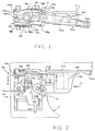
- FIGS. 1 and 2 illustrate a trigger switch assembly 10 for use in a power tool.
- the tool may be of a portable type which includes a depending pistol, grip-like handle 12 having trigger switch assembly 10 mounted thereon, which switch 10 is adapted to control operation of an electric motor (not shown), such as, for instance, a universal electric motor within the tool.
- a trigger 14 of the reciprocal spring loaded type is preferably provided to coact with a speed control switch unit 16 provided to control the speed of the electric motor in a conventionally known manner.
- Trigger switch assembly 10 may also include a locking mechanism (not shown) including a reciprocal pin for the locking trigger 14 in its full inward or maximum "on” position.
- Speed control switch unit 16 is of known construction for varying the speed of an electric motor in accordance with the inward movement of the trigger 14 from a completely outward or “off” position to a completely inward or “on” position. Speed control switch unit 16 and of itself forms no part of the present invention, and therefore will not be described in great detail. It will be understood, however, that in the embodiment shown, trigger switch assembly 10 includes trigger 14, speed control switch unit 16 and a reversing switch mechanism 18 with which the present invention is particularly concerned, with such trigger switch assembly 10 being of integral, compact construction for ready installation in a tool, appliance or the like. Electrical leads 20 may extend from the trigger switch assembly 10 and form part of an electrical power circuit in a conventional manner.
- Reversing switch mechanism 18 is received in a housing 22 formed of any suitable non-conductive material, such as, for instance, moldable plastic material.
- housing 22 is secured, molded or otherwise formed integrally to a casing 23 enclosing speed control switch unit 16 and the remainder of trigger switch assembly 10.
- a partition wall 24 (best seen in FIG. 3) forms the bottom of housing 22 and generally separates speed control switch unit 16 from reversing switch mechanism 18.
- housing 22 is generally rectangular in shape and includes end wall sections 26, 28, end side wall sections 30a, 30b, 32a and 32b.
- End wall section 28 includes a laterally extending generally cylindrical platform 34 having a cylindrical opening 35 therethrough.
- Opening portion includes an upper section 35a and a lower section 35b of substantially smaller diameter, as best seen in FIG. 6.
- Side wall sections 30a, 30b and 32a, 32b define gaps or openings 36, 38 respectively, which gaps 36, 38 have a predetermined width and communicate an interior cavity 40 which is defined by the respective wall sections with the exterior of housing 26.
- Inwardly extending locating ribs 42 are provided on end wall sections 26, 28 and locating ribs 44 are provided on side wall sections 30a, 30b, 32a and 32b.
- Side wall members 30A, 30B, 32A and 32B also include spacer ribs 46 thereon.
- Narrow throat portions or passages 48, 50 are defined between end wall sections 26, 28 and side wall sections 30a and 32a.
- bearing opening 52 is aligned along an axis designated X through housing 22.
- Bearing opening 52 includes a laterally extending recess 54 having angularly spaced straight side walls 56a and 56b.
- Recess die walls 56a and 56b are oriented at a predetermined angle relative to the longitudinal axis of housing 22.
- recess side walls 56a and 56b each define a 13 1/2 o angle relative to the longitudinal axis of housing 22.
- Posts 58 are symmetrically disposed relative to axis X and are spaced at predetermined distance from openings or gaps 36, 38.
- Reversing switch mechanism 18 includes two pairs of relatively fixed or stationary contacts, the contacts of each pair being substantially identical to each other.
- One pair is comprised of fixed contacts 60, which are located adjacent end well sections 26, 28.
- fixed contact 60 are generally L-shaped having a major leg 62 having a dentation 62a therein forming a contact portion, and a minor leg 64 having a notched end 64a forming a connector portion.
- Connector portion 64 is a preferably dimensioned to receive a standard quick connect fastener.
- Connector portion 64 however may also include an aperture 65 therethrough to facilitate a fastening screw (not shown) by which a bare lead wire can be secured to the contact 60.
- aperture 65 may include screw threads therein or be dimensioned to accept a self-taping screw.
- Fixed contacts 60 are positioned within housing 22 such that respective in dentations or contact portions 62a are symmetrically disposed relative to axis X as seen in FIG. 4. Legs 62a of respective contacts 60 extend through throat portions 48, 50 of housing 22 such that leg 64 and the connector portions 64a are disposed externally of housing 22.
- the spacing defined between end wall sections 26, 28 and side wall sections 30a, 30b and 32a,32b are dimensioned to snugly receive contacts 60 therein and to maintain contacts 60 stationary relative to housing 22.
- the second pair of fixed contracts is comprised of contacts 70 which are located adjacent side wall sections 30a, 30b, 32a and 32b.
- fixed contacts 70 are generally T-shaped having an upper leg 72 and a lower leg 74 perpendicular thereto. The ends of upper leg 72 are crimped or curved to form contact portions 72a, 72b.
- lower leg portion 74 is off-set from upper leg portion 72.
- Lower leg portion 74 defines the connector portion of contact 70.
- Fixed contacts 70 are positioned within housing 22 as best seen in FIG. 4, wherein upper leg 72 is received within the opening defined between post 58 and spacer ribs 46 on wall sections 30a, 30b, 32a and 32b.
- lower leg portion 74 extends through gaps 36, 38 inside well sections 30a, 30b, 32a and 32b to position lower leg portion 74 outside of housing 22.
- contact portions 72a and 72b are angularly disposed relative to contact portions 62a of fixed contacts 60.
- Lower leg portion 74 preferably includes an aperture 75 therethrough, which aperture 75 is preferably threaded to receive a fastening screw 77 shown in FIG. 2.
- Fastening screw 77 may be used to secure a lead 20 as shown in FIG. 2 or may be used to secure the bare end of a lead wire.
- a U-shaped recess 78 (best seen in FIG. 3) is provided in casing 23 to facilitate fastener 77 extending through leg portion 74 of contact 70.
- External ribs 79 are provided alongside recess 78 to position leg portion 74.
- a rotary switch member 80 is dimensioned to be positioned within cavity 40 and to be in operative engagement with fixed contact members 60, 70.
- Rotary switch member 80 includes a generally obround insulation element 82 (the term obround meaning that element 82 has generally planar sides and rounded ends).
- Insulation element 82 includes an upper cylindrical pivot 84, a lower cylindrical pivot 86 (best seen in FIG. 5) and a shaft 88 extending along an axis centrally disposed relative to the ends of element 82 and coaxial with axis X.
- the lower or bottom cylindrical pivot 86 includes a generally rectangular arm 86a extending to one side thereof. Cylindrical pivot 86 and arm 86a are dimensioned to be received in bearing opening 52 and bearing opening recess 54 as shown in FIG.
- Arm 86a and recess 54 are dimensioned and operable to limit angular rotation of insulation element 82 about axis X.
- insulation element 82 can move only between the positions shown in FIG. 4.
- Aligned bores 90 extend along the longitudinal axis of obround insulation member 82. Each bore 90 receives a coiled compression spring 92.
- U-shaped bridging contact members 94 are provided at the ends of insulation element 82.
- Bridging members 94 are formed of a metallic conductive material.
- a divider wall 96 is provided on each side of conductive element 82 to ensure that the ends of bridging contact members 94 do not come in contact with each other.
- Upper and lower flanges 82a and 82b are provided on insulation element 82 to confine vertically U-shaped bridging members 94. Longitudinal ribs 99 are provided along the sides of insulation element 82.
- a generally planar cover 100 is provided to enclose cavity 40.
- Cover 100 includes a cylindrical bearing opening 102 to receive upper cylindrical pivot 84 of insulation member 82.
- Three depressions 104a, 104b, 104c which are angularly spaced from each other relative to bearing opening 102 are provided on the upper surface of cover 100.
- Cover 100 includes a pair of downward extending side walls 106 dimensioned to be received within the openings or gaps 36, 38 of housing 22.
- the lower ends 106a are dimensioned to overlie lower leg portion 74 of fixed contacts 70 when the fixed contact 70 are positioned within the housing 22.
- tabs 108 Located at the corners of cover 100 are tabs 108 having an opening 110 therethrough.
- Tabs 108 are positioned in registry with ledges or ramps 112 provided on the corners of housing 22, which ledges 112 snap respectively into openings 110 of tabs 108 when cover 100 is mounted on housing 22.
- cover 100 when cover 100 is snapped-locked onto housing 22, fixed contacts 60 and 70 are “locked” into position within housing 22, and rotary element 80 is aligned along axis X with upper cylindrical pivot 84 engaging bearing opening 102 of cover 100, and lower or bottom cylindrical pivot 86 engaging bearing opening 52 in partition wall 24.
- Reversing switch mechanism 18 includes a link member 120 having a generally planar base 121 with a centrally located boss 122 thereon.
- Boss 122 includes an opening 124 which is configured to matingly engage, in press-fit fashion, shaft 88 of insulation element 82 to rotate with the same about axis X.
- Link member 120 also includes a second boss 126 located at one end of base 121.
- Boss 126 includes a cylindrical bore (not shown) extending from the lower or bottom surface of base 121 to receive a coiled compression spring 128 therein.
- the bore and coiled compression spring 128 are adapted to be in registry with depressions 104a, 104b, and 104c to bias a spherical member 130 into a selected one of the depressions based on the angular position of link 120 relative to axis X.
- a cylindrical pin 132 is provided on the other end of base 121.
- Embracing pin 132 of link member 120 is the end of an elongated actuating or operating lever 140 which is pivotable about an axis Y through platform 34 on end well section 28, which axis Y extends generally parallel to axis X.
- the underside of actuating lever 140 is provided with a pivot pin 142 preferably integrally formed therewith.
- Pivot pin 142 (best seen in FIG. 6) includes an enlarged cylindrical bearing section 144 at its juncture with lever 140 and a flared end portion 146. Pivot pin 142 is received within opening 35 in platform 34 in snap lock fashion as seen in FIG. 6 wherein pin section 144 is disposed in opening 35a.
- actuating lever 140 One end of actuating lever 140 includes a slot 148 for receiving the aforementioned cylindrical pin 132 of link 120.
- the other end of operating lever 140 is provided with a tab portion 150 for convenient movement of operating lever 140 about axis Y by operation of a finger.
- rotation of operating lever 140 about pivot pin 142 is operative to rotate link 120 about axis X.
- the lower surface of operating lever 140 includes a downward extending projection 152, best seen in FIGS. 1 and 2.
- Projection 152 is operative to engage a wall member 154 on trigger 14 when operating lever 140 is aligned with the longitudinal axis of the switch assembly.
- FIG. 1 illustrates operating lever 140 in an electrically conducting position.
- link 120 is oriented such that spherical member 130 is positioned in depression 104c.
- insulation element 82 is shown in FIG. 4.
- U-shaped bridging contact members 94 connect contact portions 62a of fixed contacts 60 with contact portions 72g of fixed contacts 70.
- the longitudinal axis of insulation member 82 is positioned to one side of contact portion 62a (as indicated by the axially aligned compression springs 92).
- coiled compression springs 92 urge U-shaped bridging contact members 94 into positive engagement with the contact portions of the respective fixed contacts.
- Arm 86a on lower cylindrical pivot 86 limits movement of insulation element 82 to that shown in FIG. 4. Movement of operating lever 140 to the other side of trigger 14 causes link 120 to pivot rotary switch member 80 from the position shown in FIG. 4 to the position shown in phantom in the same figure. In this position, U-shaped bridging members 94 engage contact portion 62a of fixed contact 60 and contact portion 72a of fixed contacts 70, wherein the plurality of the switch has been reversed by contact of the U-shaped bridging contact members 94 with contact portions 62a if fixed contacts 60 and contact portions 72a of fixed contacts 70. A central, neutral position is also illustrated in phantom in FIG. 4. In this position, U-shaped conductive bridging members 94 engage only contact portion 62a of fixed contacts 60. This position is assumed when lever arm 140 is aligned relative to the direction of movement of trigger 14. Importantly, in this position, projection 152 restricts movement of trigger 14 to the full "on" position, as set forth above.
- the present invention thus provides an extremely compact, three-position reversing switch which includes relatively few parts and yet is operable with high current/low voltage batteries.
- the conductive members of the switch arrangement i.e. contacts 60, 70 and U-shaped bridging contact members 94 are formed from relatively thick copper strips.
- contacts 60, 70 and 94 are preferably die stamped from copper sheet and have a width of approximately 5/16 inch.
- fixed contacts 60, 70 and U-shaped bridging contact member 94 provide a cross sectional area of square inches.
- This relatively large cross sectional area provides substantially increased current capacity than switches known heretofore.
- the cross sectional area of a contact in the reversing switch disclosed in aforementioned U.S. Letters Patent No. 3,691,322 is approximately square inches.
- a switch according to the present invention provides substantially more cross sectional area, which increases current conducting capacity and reduced resistance and heat.
- fixed contacts 60 and 70 each include a portion external of housing 22, i.e. legs 64 and 74 respectively. These external portions act as a heat sink to conduct heat, generated within the switch due to resistance and arcing between respective contact portions, to the external areas of the switch housing. Also important air spaces or gaps are defined around fixed contact members 60 and 70. Spacer ribs 46 on side walls 30a, 30b, 32a and 32b, as well as ribs 98 on insulation element 82, produce air spaces surrounding the contact elements, which spaces reduce heat transfer to the housing 22 and likewise assist in dissipating heat from cavity 40. Accordingly, the present invention provides contact members which produce substantially increased current conduction, and at the same time act as heat sinks for dissipating heat from within the switch.
- the invention also provides a reversing switch of the aforedescribed type which can be used in conjunction with a trigger assembly for conveniently reverse the direction of motor movement in conjunction with actuation of the trigger for controlling the electric motor.
- a reversing switch of the aforedescribed type which can be used in conjunction with a trigger assembly for conveniently reverse the direction of motor movement in conjunction with actuation of the trigger for controlling the electric motor.
- another important aspect of the present invention is forming pivot pin 142 as an integral part of operating lever 140 and connecting operating lever 140 to housing 22 by means of a snap-lock connection.
- metallic rivets or pins have been used to secure the operating lever to the switch housing.
- the present modification thus provides a simpler and less expensive fabrication and assembly of the switch unit.
Landscapes
- Push-Button Switches (AREA)
- Rotary Switch, Piano Key Switch, And Lever Switch (AREA)
Claims (8)
- Kompakte Auslöseschalterbaugruppe (10) zur Betriebssteuerung eines Elektromotors, beinhaltend
ein Isoliergehäuse (22);
in dem Gehäuse eine Schalteinrichtung (16), die die Motorgeschwindigkeit steuert;
wobei die Auslösebaugruppe mit der Motorgeschwindigkeits-Steuerungsschalteinrichtung (16) verbunden ist, damit der Betrieb des Elektromotors gesteuert werden kann,
die Auslösebaugruppe einen Auslöser (14) enthält, der federbelastet ist zwischen einer ersten Stellung, die aus dem Gehäuse (22) vorsteht, und einer zweiten Stellung, die näher am Gehäuse (22) liegt, gekennzeichnet durch
einen Dreifachschalter (18) im Gehäuse, der zwei starre Kontaktpaare (60, 70) hat und ein längliches Isolierteil (80), das um eine Achse durch das Gehäuse hin und herschwenken kann, wobei das Isolierteil zwischen den starren Kontaktpaaren angeordnet ist und die Kontakte Abschnitte (64, 74) außerhalb des Gehäuses (22) haben, sowie
durch jeweils ein U-förmiges leitendes Brückenelement (94) auf den gegenüberliegenden Enden des länglichen Isolierteils (80), wobei ein Hin und Herschwenken des länglichen Isolierteils (80) die U-förmigen leitenden Brückenelemente (94) selektiv mit den gewählten starren Kontakten (60, 70) eingreifen läßt oder diese voneinander trennt, so daß die U-förmigen, leitenden Brückenelemente (94) Kontaktteile zwischen den starren Kontakten (60, 70) sind. - Kompakte Auslöseschalterbaugruppe nach Anspruch 1, gekennzeichnet durch eine Hebeleinrichtung (140), die mit dem Dreifachschalter (18) verbunden ist und dessen Stellung steuert.
- Kompakte Auslöseschalterbaugruppe nach Anspruch 2, wobei die Hebeleinrichtung (140) eine Einrichtung (152) enthält, die mit dem Auslöser (14) eingreift und dessen Bewegung verhindert, sollte der Dreifachschalter (18) in elektrisch nichtleitender Stellung stehen.
- Kompakte Auslöseschalterbaugruppe nach Anspruch 2 oder 3, dadurch gekennzeichnet, daß die Hebeleinrichtung (140) einen Kippzapfen (142) enthält, der an das Gehäuse (22) festschnappen kann.
- Kompakte Auslöseschalterbaugruppe nach irgendeinem vorhergehenden Anspruch, dadurch gekennzeichnet, daß die Motorgeschwindigkeits-Steuerungsschalteinrichtung (16) ein variabler Geschwindigkeitsschalter ist.
- Kompakte Auslöseschalterbaugruppe nach irgendeinem vorhergehenden Anspruch, dadurch gekennzeichnet, daß der Dreifachschalter ein Umkehrschalter ist, wobei eine Stellung des Umkehrschalters nichtleitend ist.
- Kompakte Schaltvorrichtung nach einem der Ansprüche 2, 3 oder 4 oder nach Anspruch 5 oder 6, wenn abhängig von Anspruch 2, gekennzeichnet durch eine Bedienerbetätigbare Hebeleinrichtung (140), die mit dem länglichen Isolierteil verbunden ist, so daß die Stellungen des Dreifachschalters wählbar sind.
- Kompakte Schaltvorrichtung nach Anspruch 7, wobei der Dreifachschalter gekennzeichnet ist durch eine Sicherungseinrichtung (126, 128, 130, 104a-c), die die Hebeleinrichtung (140) in einer der drei Stellungen sichern kann, damit die U-förmigen, leitenden Brückenelemente (94) in Eingriff mit dem gewählten der starren Kontakte (60, 70) bleiben.
Applications Claiming Priority (3)
| Application Number | Priority Date | Filing Date | Title |
|---|---|---|---|
| US07/182,158 US4864083A (en) | 1988-04-15 | 1988-04-15 | Reversing switch |
| US182158 | 1988-04-15 | ||
| PCT/US1989/001588 WO1989009997A1 (en) | 1988-04-15 | 1989-04-14 | D.c. reversing switch |
Publications (3)
| Publication Number | Publication Date |
|---|---|
| EP0368961A1 EP0368961A1 (de) | 1990-05-23 |
| EP0368961A4 EP0368961A4 (en) | 1991-10-30 |
| EP0368961B1 true EP0368961B1 (de) | 1994-06-08 |
Family
ID=22667290
Family Applications (1)
| Application Number | Title | Priority Date | Filing Date |
|---|---|---|---|
| EP89905359A Expired - Lifetime EP0368961B1 (de) | 1988-04-15 | 1989-04-14 | Umkehrschaltvorrichtung für gleichstrom |
Country Status (6)
| Country | Link |
|---|---|
| US (1) | US4864083A (de) |
| EP (1) | EP0368961B1 (de) |
| JP (1) | JP3072599B2 (de) |
| KR (1) | KR940004146B1 (de) |
| DE (1) | DE68915943T2 (de) |
| WO (1) | WO1989009997A1 (de) |
Families Citing this family (19)
| Publication number | Priority date | Publication date | Assignee | Title |
|---|---|---|---|---|
| DE4038786A1 (de) * | 1990-12-05 | 1992-06-11 | Bsg Schalttechnik | Vorrichtung zur steuerung oder regelung von durch akkus versorgter geraete |
| DE4038787A1 (de) * | 1990-12-05 | 1992-06-11 | Bsg Schalttechnik | Vorrichtung zur steuerung oder regelung von durch akkus versorgter geraete |
| DE4038785A1 (de) * | 1990-12-05 | 1992-06-11 | Bsg Schalttechnik | Vorrichtung zur steuerung oder regelung von durch akkus versorgter geraete |
| JP2525661Y2 (ja) * | 1991-12-03 | 1997-02-12 | マブチモーター株式会社 | 玩具用モータの接点構造 |
| US5349143A (en) * | 1993-01-19 | 1994-09-20 | Lucerne Products, Inc. | Reversible electrical switch |
| US5600107A (en) * | 1995-07-27 | 1997-02-04 | Eaton Corporation | Electric switch with dynamic brake contact shared for making and breaking a power circuit |
| JPH09320391A (ja) * | 1996-05-29 | 1997-12-12 | Shuji Matsumura | 開閉スイッチ |
| DE19722709C2 (de) * | 1996-06-03 | 2002-02-07 | Omron Tateisi Electronics Co | Schaltvorrichtung |
| DE19909854A1 (de) * | 1998-03-11 | 1999-09-16 | Marquardt Gmbh | Elektrischer Schalter |
| US6091035A (en) | 1998-08-14 | 2000-07-18 | Black & Decker, Inc. | Lockout mechanism for power tool |
| US6057518A (en) | 1998-08-14 | 2000-05-02 | Black & Decker, Inc. | Lockout mechanism for power tool |
| US7148433B1 (en) | 2006-01-12 | 2006-12-12 | Tyco Electronics Corporation | Reversing switch mechanism |
| JP5564399B2 (ja) * | 2010-10-26 | 2014-07-30 | 佐鳥エス・テック株式会社 | 電動工具用正転・逆転切替スイッチ |
| US9321112B2 (en) | 2011-05-18 | 2016-04-26 | Black & Decker Inc. | Power saw tool |
| US8493172B2 (en) | 2011-09-30 | 2013-07-23 | Snap-On Incorporated | Variable speed toggle trigger |
| CN103456523B (zh) * | 2012-05-28 | 2016-05-25 | 上海拜骋电器有限公司 | 换向开关 |
| DE102012214030A1 (de) * | 2012-08-08 | 2014-02-13 | Robert Bosch Gmbh | Elektrisches Handwerkzeug mit diskretem Bedienelement |
| US9559628B2 (en) | 2013-10-25 | 2017-01-31 | Black & Decker Inc. | Handheld power tool with compact AC switch |
| JP6838012B2 (ja) * | 2018-06-29 | 2021-03-03 | 佐鳥電機株式会社 | スイッチ |
Family Cites Families (15)
| Publication number | Priority date | Publication date | Assignee | Title |
|---|---|---|---|---|
| US1399411A (en) * | 1919-05-12 | 1921-12-06 | Stechbart Bruno | Reversing-switch |
| US2478690A (en) * | 1946-12-09 | 1949-08-09 | Furnas Electric Co | Rotary reversing switch |
| CH493086A (fr) * | 1968-07-29 | 1970-06-30 | Skil Nederland Nv | Commutateur |
| US3649780A (en) * | 1970-05-13 | 1972-03-14 | Arrow Hart Inc | Electric reversing switch |
| US3637967A (en) * | 1970-06-26 | 1972-01-25 | Skil Corp | Switch of the reversing-type |
| US3703646A (en) * | 1970-12-11 | 1972-11-21 | Murphy Ind Inc G W | Electric tool with trigger switch and lock-out arrangement |
| US3691322A (en) * | 1971-01-28 | 1972-09-12 | Lucerne Products Inc | Reversing switch |
| US3742364A (en) * | 1971-10-22 | 1973-06-26 | Lucerne Products Inc | Reversing switch lever |
| US3755640A (en) * | 1972-07-27 | 1973-08-28 | Skie Corp | Reversing switch for a power tool with separate selectively movable contact carriers |
| US4097704A (en) * | 1976-08-02 | 1978-06-27 | Cutler-Hammer, Inc. | Industrial reversing speed control trigger switch with snap-in modules |
| US4277667A (en) * | 1978-06-23 | 1981-07-07 | Matsushita Electric Industrial Co., Ltd. | Induction heating apparatus with negative feedback controlled pulse generation |
| US4450323A (en) * | 1981-11-24 | 1984-05-22 | Hitachi Koki Company, Limited | Reversible switch |
| DE3146984A1 (de) * | 1981-11-26 | 1983-06-01 | Hitachi Koki Co., Ltd., Tokyo | Umpolschalter |
| US4396811A (en) * | 1981-12-09 | 1983-08-02 | Peter Kljucaricek | D.C. Power reversing switch |
| US4678871A (en) * | 1985-07-22 | 1987-07-07 | Skil Corporation | Reversing switch for rechargeable hand tool |
-
1988
- 1988-04-15 US US07/182,158 patent/US4864083A/en not_active Expired - Fee Related
-
1989
- 1989-04-14 EP EP89905359A patent/EP0368961B1/de not_active Expired - Lifetime
- 1989-04-14 WO PCT/US1989/001588 patent/WO1989009997A1/en active IP Right Grant
- 1989-04-14 DE DE68915943T patent/DE68915943T2/de not_active Expired - Fee Related
- 1989-04-14 JP JP1504806A patent/JP3072599B2/ja not_active Expired - Lifetime
- 1989-04-14 KR KR1019890702372A patent/KR940004146B1/ko not_active IP Right Cessation
Also Published As
| Publication number | Publication date |
|---|---|
| JP3072599B2 (ja) | 2000-07-31 |
| WO1989009997A1 (en) | 1989-10-19 |
| DE68915943T2 (de) | 1995-01-05 |
| EP0368961A4 (en) | 1991-10-30 |
| DE68915943D1 (de) | 1994-07-14 |
| KR940004146B1 (ko) | 1994-05-13 |
| JPH03500709A (ja) | 1991-02-14 |
| EP0368961A1 (de) | 1990-05-23 |
| KR900701025A (ko) | 1990-08-17 |
| US4864083A (en) | 1989-09-05 |
Similar Documents
| Publication | Publication Date | Title |
|---|---|---|
| EP0368961B1 (de) | Umkehrschaltvorrichtung für gleichstrom | |
| EP0528478B1 (de) | Netzunabhängiges Kraftbetriebenes Werkzeug | |
| US4100383A (en) | Industrial reversing speed control trigger switches having snap-in modules | |
| US4179644A (en) | Power tool switch including speed control | |
| US4737661A (en) | Variable speed trigger switch | |
| US4095072A (en) | Industrial speed control trigger switch with integral reversing switch | |
| US6104105A (en) | Electrical switch | |
| EP0213830A2 (de) | Drucktaster für veränderliche Geschwindigkeiten | |
| US4968922A (en) | Reversing switch | |
| US4764745A (en) | Slide switch with externally mounted protective circuit breaker | |
| US3814886A (en) | Miniature electrical reversing switch mounted on trigger operated switch for hand-held tools | |
| CN113113258A (zh) | 旋转按压控制开关 | |
| US4123634A (en) | Snap-action switch with contact wiping action | |
| JP3699491B2 (ja) | トリガースイッチ | |
| US3261930A (en) | Rotary selector switch with improved spring biasing structure | |
| US5581059A (en) | Rotary switch | |
| US5811745A (en) | Three-way switch | |
| US5600107A (en) | Electric switch with dynamic brake contact shared for making and breaking a power circuit | |
| US3766348A (en) | Two part casing for trigger switch with one part mounting all switch contact members | |
| WO1993006647A1 (en) | Reverse switch assembly | |
| US3194898A (en) | Selector switches of the trigger actuated type | |
| JP3671049B2 (ja) | 電動工具 | |
| CA1105531A (en) | Power tool switch including speed control | |
| CN217902909U (zh) | 电路保护开关和电器设备 | |
| US2645685A (en) | Multiposition switch |
Legal Events
| Date | Code | Title | Description |
|---|---|---|---|
| PUAI | Public reference made under article 153(3) epc to a published international application that has entered the european phase |
Free format text: ORIGINAL CODE: 0009012 |
|
| AK | Designated contracting states |
Kind code of ref document: A1 Designated state(s): DE FR GB IT |
|
| 17P | Request for examination filed |
Effective date: 19900412 |
|
| A4 | Supplementary search report drawn up and despatched |
Effective date: 19910912 |
|
| AK | Designated contracting states |
Kind code of ref document: A4 Designated state(s): DE FR GB IT |
|
| 17Q | First examination report despatched |
Effective date: 19920319 |
|
| GRAA | (expected) grant |
Free format text: ORIGINAL CODE: 0009210 |
|
| ITF | It: translation for a ep patent filed | ||
| AK | Designated contracting states |
Kind code of ref document: B1 Designated state(s): DE FR GB IT |
|
| REF | Corresponds to: |
Ref document number: 68915943 Country of ref document: DE Date of ref document: 19940714 |
|
| ET | Fr: translation filed | ||
| PLBE | No opposition filed within time limit |
Free format text: ORIGINAL CODE: 0009261 |
|
| STAA | Information on the status of an ep patent application or granted ep patent |
Free format text: STATUS: NO OPPOSITION FILED WITHIN TIME LIMIT |
|
| 26N | No opposition filed | ||
| PGFP | Annual fee paid to national office [announced via postgrant information from national office to epo] |
Ref country code: GB Payment date: 19970516 Year of fee payment: 9 |
|
| PGFP | Annual fee paid to national office [announced via postgrant information from national office to epo] |
Ref country code: FR Payment date: 19970527 Year of fee payment: 9 |
|
| PGFP | Annual fee paid to national office [announced via postgrant information from national office to epo] |
Ref country code: DE Payment date: 19970630 Year of fee payment: 9 |
|
| PG25 | Lapsed in a contracting state [announced via postgrant information from national office to epo] |
Ref country code: GB Free format text: LAPSE BECAUSE OF NON-PAYMENT OF DUE FEES Effective date: 19980414 |
|
| PG25 | Lapsed in a contracting state [announced via postgrant information from national office to epo] |
Ref country code: FR Free format text: THE PATENT HAS BEEN ANNULLED BY A DECISION OF A NATIONAL AUTHORITY Effective date: 19980430 |
|
| GBPC | Gb: european patent ceased through non-payment of renewal fee |
Effective date: 19980414 |
|
| PG25 | Lapsed in a contracting state [announced via postgrant information from national office to epo] |
Ref country code: DE Free format text: LAPSE BECAUSE OF NON-PAYMENT OF DUE FEES Effective date: 19990202 |
|
| REG | Reference to a national code |
Ref country code: FR Ref legal event code: ST |
|
| PG25 | Lapsed in a contracting state [announced via postgrant information from national office to epo] |
Ref country code: IT Free format text: LAPSE BECAUSE OF NON-PAYMENT OF DUE FEES Effective date: 20050414 |