EP0368174B1 - Dichtungsprofil für Tunnel-Segmente - Google Patents
Dichtungsprofil für Tunnel-Segmente Download PDFInfo
- Publication number
- EP0368174B1 EP0368174B1 EP89120415A EP89120415A EP0368174B1 EP 0368174 B1 EP0368174 B1 EP 0368174B1 EP 89120415 A EP89120415 A EP 89120415A EP 89120415 A EP89120415 A EP 89120415A EP 0368174 B1 EP0368174 B1 EP 0368174B1
- Authority
- EP
- European Patent Office
- Prior art keywords
- profile
- sealing
- sealing arrangement
- recess
- width
- Prior art date
- Legal status (The legal status is an assumption and is not a legal conclusion. Google has not performed a legal analysis and makes no representation as to the accuracy of the status listed.)
- Expired - Lifetime
Links
- 238000007789 sealing Methods 0.000 title claims description 47
- XLYOFNOQVPJJNP-UHFFFAOYSA-N water Substances O XLYOFNOQVPJJNP-UHFFFAOYSA-N 0.000 claims description 4
- 239000013536 elastomeric material Substances 0.000 claims description 2
- 230000001747 exhibiting effect Effects 0.000 claims 2
- 230000000284 resting effect Effects 0.000 claims 1
- 229920001971 elastomer Polymers 0.000 description 4
- 238000010276 construction Methods 0.000 description 2
- 230000000694 effects Effects 0.000 description 2
- 239000007787 solid Substances 0.000 description 2
- 229910001018 Cast iron Inorganic materials 0.000 description 1
- 229910000831 Steel Inorganic materials 0.000 description 1
- 230000003213 activating effect Effects 0.000 description 1
- 239000002131 composite material Substances 0.000 description 1
- 239000004567 concrete Substances 0.000 description 1
- 230000007423 decrease Effects 0.000 description 1
- 238000006073 displacement reaction Methods 0.000 description 1
- 239000000806 elastomer Substances 0.000 description 1
- 238000009863 impact test Methods 0.000 description 1
- 238000001746 injection moulding Methods 0.000 description 1
- 239000000463 material Substances 0.000 description 1
- 239000004033 plastic Substances 0.000 description 1
- 239000011150 reinforced concrete Substances 0.000 description 1
- 239000010959 steel Substances 0.000 description 1
Images

Classifications
-
- E—FIXED CONSTRUCTIONS
- E21—EARTH OR ROCK DRILLING; MINING
- E21D—SHAFTS; TUNNELS; GALLERIES; LARGE UNDERGROUND CHAMBERS
- E21D11/00—Lining tunnels, galleries or other underground cavities, e.g. large underground chambers; Linings therefor; Making such linings in situ, e.g. by assembling
- E21D11/38—Waterproofing; Heat insulating; Soundproofing; Electric insulating
- E21D11/385—Sealing means positioned between adjacent lining members
-
- E—FIXED CONSTRUCTIONS
- E21—EARTH OR ROCK DRILLING; MINING
- E21D—SHAFTS; TUNNELS; GALLERIES; LARGE UNDERGROUND CHAMBERS
- E21D11/00—Lining tunnels, galleries or other underground cavities, e.g. large underground chambers; Linings therefor; Making such linings in situ, e.g. by assembling
- E21D11/38—Waterproofing; Heat insulating; Soundproofing; Electric insulating
- E21D11/385—Sealing means positioned between adjacent lining members
- E21D11/388—Sealing means positioned between adjacent lining members having longitudinal cavities communicating with the exterior on the outer side of the lining elements
Definitions
- the invention relates to a sealing arrangement according to the preamble of claim 1.
- Such an arrangement is known from GB-A-2 178 114.
- the sealing frames of a segment made of concrete, steel, reinforced concrete or cast iron mostly consist of four composite strand-shaped sealing profiles (profiled strips) made of elastomeric material, that is, of rubber or rubber-like plastic, the frame corners preferably being produced by the injection molding process.
- the tunnel construction in segmental construction with a special arrangement of the segments. It is often sufficient if each segment has a sealing frame. In special circumstances, however, it may be necessary to provide each segment with a double sealing frame, it being possible for the two parallel sealing frames to be connected to one another with an additional sealing cross profile (EP-A-0 337 177).
- the sealing profiles or sealing frames are usually located in a corresponding groove (groove depth d, groove width w) of the tunnel segment.
- a sealing profile which, viewed in cross-section, is of asymmetrical shape, the asymmetry being caused by the fact that a recess is located in the flat front edge back of the profile towards the outside of the segment (water side).
- this front edge back has a support rib which is located in a corresponding groove in the segment.
- a rubber profile for sealing end walls of tunnel segments pressed against one another is known, which also has an asymmetrical cross-sectional shape.
- This profile body has a sealing lip that faces the outside of the tunnel segment so that the water pressure can increase the sealing effect.
- a sealing lip is also referred to in this context as a "pressure-activating lip”.
- sealing profiles have mostly been used in tunnel projects, which are mirror-symmetrical in cross-section (based on the vertical longitudinal profile of the profile). It has been found that profile strips which have longitudinal groove grooves and channels (GB-B-2 170 561, GB-B-2 178 114, GB-B-2 182 987, EP-A-0 255 600, EP -A-0 306 796), are particularly effective with regard to their sealing function.
- profile strips which have longitudinal groove grooves and channels (GB-B-2 170 561, GB-B-2 178 114, GB-B-2 182 987, EP-A-0 255 600, EP -A-0 306 796), are particularly effective with regard to their sealing function.
- density values of 4 to 20 bar were achieved. With groove dimensions d / w ⁇ 0.18 and for high tightness of ⁇ 20 bar with required vertical pressing of more than 30%, the sealing profiles developed so far can no longer be designed to match the groove volume.
- the invention is based on the surprising finding that asymmetrical sealing profiles according to the characterizing part of claim 1 have a very high sealing performance.
- the gap (1) should be sealed with the distance S o (unloaded state) between two adjacent segments (2, 3).
- a strand-shaped sealing profile (6) made of rubber or rubber-like material is inserted into the grooves (4, 5).
- Each sealing profile has a pressure-activating lip (8) towards the outside of the segment (7) and a profile foot (9) which is trough-shaped.
- the pressure-activating lip (8) is oriented in the unloaded state from the profile back (10) towards the middle of the gap (11) to the pressure water side.
- the lip (8) according to the invention increases the sealing profile with only a small volume requirement. In the loaded, ie compressed state (gap distance S1), the gap (12) between the two sealing profiles (6) disappears.
- the profile foot (9) has a support (13) on the groove slope (14), which prevents a displacement of the profile (6) when compressed.
- the tub-like profile foot (9) has the task of centering the solid sealing body in the groove (4, 5), so that a minimum contact width of the profiles remains guaranteed even when the sealing profiles are offset.
- the three groove grooves (15, 16, 17) are arranged symmetrically to one another, the middle groove (16) being deeper and wider than the neighboring grooves (15, 17).
- the line (19b) is also the reference point for the profile height H.
- the trough-shaped profile foot (9; area B) can take up to 40% of the groove width w (corresponds to the total width of the profile base side). This upper limit should not be exceeded so that the profile body (area A) still exerts a sufficient sealing effect even when there is a segment offset.
- the support (13), which gives the profile foot (9) the trough-shaped shape, has an overall height which corresponds approximately to half the groove depth d.
- the solid profile base body (area A) has three groove grooves (22, 23, 24) similar to the sealing profile (6) according to FIG. 1, the middle groove (23) here having a different shape than the two neighboring grooves (22, 24) .
- a channel (25) is arranged directly above the central groove (23).
- the sealing profile (26) has two groove grooves (27, 28) which have a different shape and size, and three substantially uniform channels (29, 30, 31).
- groove grooves and channels are arranged asymmetrically to one another. This gives the profile (26) in addition to the two asymmetry elements according to the invention, namely lip (8) and profile foot (9), further asymmetry elements.
Landscapes
- Engineering & Computer Science (AREA)
- Structural Engineering (AREA)
- Mining & Mineral Resources (AREA)
- Architecture (AREA)
- Civil Engineering (AREA)
- Life Sciences & Earth Sciences (AREA)
- General Life Sciences & Earth Sciences (AREA)
- Geochemistry & Mineralogy (AREA)
- Geology (AREA)
- Lining And Supports For Tunnels (AREA)
- Gasket Seals (AREA)
- Sealing With Elastic Sealing Lips (AREA)
Description
- Die Erfindung betrifft eine Dichtanordnung gemäß Oberbegriff des Anspruchs 1. Solch eine Anordnung ist aus der GB-A-2 178 114 bekannt.
- Die Dichtungsrahmen eines Segmentes aus Beton, Stahl, Stahlbeton oder Gußeisen bestehen zumeist aus vier zusammengesetzten strangförmigen Dichtungsprofilen (Profilbänder) aus elastomerem Werkstoff, d.h. aus Gummi oder gummiähnlichem Kunststoff, wobei die Rahmenecken vorzugsweise nach dem Injektion-Molding-Verfahren hergestellt werden. Von besonderer Bedeutung ist der Tunnelbau in Tübbing-Bauweise mit spezieller Anordnung der Segmente. Häufig genügt es, wenn jedes Segment einen Dichtungsrahmen aufweist. Unter besonderen Umständen kann es jedoch erforderlich werden, jedes Segment mit einem Doppeldichtungsrahmen zu versehen, wobei die beiden parallel verlaufenden Dichtungsrahmen mit einem zusätzlichen Dichtungsquerprofil (EP-A-0 337 177) miteinander verbunden sein können. Die Dichtungsprofile bzw. Dichtungsrahmen befinden sich meistens in einer entsprechenden Nut (Nuttiefe d, Nutbreite w) des Tunnel-Segmentes. Unter Einwirkung einer Kraft verringert sich der Spaltabstand zweier Tunnel-Segmente von So (Abstand im unbelasteten Zustand) auf S₁ (Abstand im belasteten Zustand). Dadurch werden die beiden gegenüberliegenden Elastomer-Profile zusammengepreßt, was die Abdichtung des Spaltes zur Folge hat.
- Aus der DE-U-74 32 945 ist ein Dichtungsprofil bekannt, das im Querschnitt gesehen von asymmetrischer Gestalt ist, wobei die Asymmetrie dadurch hervorgerufen wird, daß sich zur Segment-Außenseite (Wasserseite) hin eine Aussparung im ebenflächigen Stirnkantenrücken des Profiles befindet. Außerdem weist dieser Stirnkantenrücken eine Stützrippe auf, die sich in einer entsprechenden Nut des Segmentes befindet.
- Aus der DE-A-31 01 332 ist ein Gummiprofil zum Abdichten von gegeneinander gepreßten Stirnwänden von Tunnel-Segmenten bekannt, das ebenfalls eine asymmetrische Querschnittsgestalt besitzt. Dabei weist dieser Profilkörper eine Dichtlippe auf, die der Außenseite des Tunnel-Segmentes zugekehrt ist, damit der Wasserdruck die Dichtwirkung erhöhen kann. Eine derartige Dichtlippe bezeichnet man in diesem Zusammenhang auch als "druckaktivierende Lippe".
- Bisher jedoch wurden bei Tunnelprojekten zumeist Dichtungsprofile eingesetzt, die im Querschnitt gesehen spiegelsymmetrisch (bezogen auf die senkrechte Profil-Längsmittelebene) sind. Dabei hat sich herausgestellt, daß Profilbänder, die in Längsrichtung verlaufende Rillennuten und Kanäle besitzen (GB-B-2 170 561, GB-B-2 178 114, GB-B-2 182 987, EP-A-0 255 600, EP-A-0 306 796), hinsichtlich ihrer Dichtfunktion besonders wirksam sind. Je nach Profilstruktur und tunnelspezifischen Kriterien (d, w, So, S₁, Segmentversatz) wurden Dichtwerte von 4 bis 20 bar erzielt. Bei Nutmaßen d/w ≧ 0,18 und für hohe Dichtheiten von ≧ 20 bar mit erforderlichen vertikalen Verpressungen von mehr als 30 % können die bisher entwickelten Dichtungsprofile nicht mehr auf das Nutvolumen angepaßt konstruiert werden.
- Der Erfindung liegt die überraschende Erkenntnis zugrunde, daß asymmetrische Dichtungsprofile gemäß Kennzeichen des Anspruchs 1 eine sehr hohe Dichtleistung aufweisen.
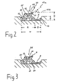
- Die Erfindung wird nun anhand von Ausführungsbeispielen unter Bezugnahme auf schematische Zeichnungen sowie in Verbindung mit Daten aus Dichtheitsprüfungen näher erläutert. Dabei zeigen die Fig. 1 bis 3 die erfindungsgemäßen Dichtungsprofile im Querschnitt gesehen.
- Nach Fig. 1 soll der Spalt (1) mit dem Abstand So (unbelasteter Zustand) zweier angrenzender Segmente (2, 3) abgedichtet werden. Zu diesem Zweck werden in die Nuten (4, 5) jeweils ein strangförmiges Dichtungsprofil (6) aus Gummi oder gummiähnlichem Werkstoff eingesetzt. Jedes Dichtungsprofil weist zur Segment-Außenseite (7) hin eine druckaktivierende Lippe (8) sowie einen Profilfuß (9) auf, der wannenförmig ausgebildet ist. Die druckaktivierende Lippe (8) ist im unbelasteten Zustand vom Profilrücken (10) her in Richtung Spaltmitte (11) zur Druckwasserseite ausgerichtet. Die erfindungsgemäße Lippe (8) erhöht das Dichtungsprofil bei nur geringem Volumenbedarf. Im belasteten, d.h. verpreßten Zustand (Spaltabstand S₁) verschwindet der Zwischenraum (12) zwischen den beiden Dichtungsprofilen (6). Der Profilfuß (9) weist eine Abstützung (13) an der Nutschräge (14) auf, wodurch eine Verschiebung des Profiles (6) bei Kompression verhindert wird. Der wannenartige Profilfuß (9) hat die Aufgabe, den massiven Dichtungskörper in der Nut (4, 5) zu zentrieren, so daß auch bei einem Versatz der Dichtungsprofile eine Mindestkontaktbreite der Profile garantiert bleibt. Die drei Rillennuten (15, 16, 17) sind symmetrisch zueinander angeordnet, wobei die mittlere Nut (16) tiefer und breiter ist als die Nachbarnuten (15, 17).
- Anhand des Dichtungsprofiles (18) nach Fig. 2 werden nun hinsichtlich der erfindungsgemäßen Asymmetrieelemente (Lippe 8, Profilfuß 9) strukturelle Details beschrieben. Die Richtung der druckaktivierenden Lippe (8) im unbelasteten Zustand ist hier durch die Linie (19a) veranschaulicht, wobei diese Linienführung die Resultierende der beiden in einem unterschiedlichen Winkel zulaufenden Lippenflanken (20, 21) ist. Die in den Ansprüchen 1 und 2 angegebenen Winkelbereiche α ergeben sich aus den Linienführungen (19a, 19b), wobei die Linie (19b) den Verlauf der Spaltmitte angibt.
- Die Linie (19b) ist zugleich Bezugspunkt für die Profilhöhe H. Der wannenförmige Profilfuß (9; Bereich B) kann bis zu 40 % der Nutbreite w (entspricht der Gesamtbreite der Profilbasisseite) einnehmen. Dieser obere Grenzwert sollte nicht überschritten werden, damit der Profilgrundkörper (Bereich A) auch noch bei Segmentversatz noch eine ausreichende Dichtwirkung ausübt. Die Abstützung (13), die dem Profilfuß (9) die wannenförmige Gestalt gibt, weist eine Gesamthöhe auf, die etwa der halben Nuttiefe d entspricht. Der massive Profilgrundkörper (Bereich A) weist ähnlich dem Dichtungsprofil (6) nach Fig. 1 drei Rillennuten (22, 23, 24) auf, wobei die mittlere Nut (23) hier eine andere Form hat als die beiden Nachbarnuten (22, 24). Direkt über der mittleren Nut (23) ist ein Kanal (25) angeordnet.
- Nach Fig. 3 weist das Dichtungsprofil (26) zwei Rillennuten (27, 28), die eine unterschiedliche Form und Größe haben, und drei im wesentlichen gleichförmige Kanäle (29, 30, 31) auf. Rillennuten und Kanäle sind im Gegensatz zu den Profilen gemäß Fig. 1 und 2 asymmetrisch zueinander angeordnet. Dadurch erhält das Profil (26) neben den beiden erfindungsgemäßen Asymmetrieelementen, nämlich Lippe (8) und Profilfuß (9), weitere Asymmetrieelemente.
- Die folgende Tabelle faßt die Ergebnisse der experimentellen Dichtheitsprüfungen, die bezüglich der Dichtungsprofile gemäß Fig. 1 bis 3 durchgeführt wurden, zusammen.
Dichtungsprofil Dichtheitswert (bar) bei S₁ = 6 mm ohne Versatz 10 mm Versatz Fig. 1 50 10 Fig. 2 55 8 Fig. 3 60 12 - Allgemeine Bedingungen:
So = 17 mm
d = 6,5 mm
w = 37 mm (entspricht der Profilbreite an der Basisseite)
H = 15 mm
α = 20°
Breite des Profilfußes (Bereich B): 32 % bezogen auf w
Stärke der druckaktivierenden Lippe (8): 3 mm
Stärke des Profilfußes (9): 2 mm - Sonstige Versuchsbedingungen:
- Kreuzstoßprüfung
2 bar/15 min/schrittweise
Drucksteigerung
Claims (9)
- Dichtanordnung,a) bestehend aus Tunnel-Segmenten (2, 3), die jeweils mit einer umlaufenden Nut (4, 5; mit Nutbreite (w) und Nuttiefe (d) versehen sind welche sich gegenüber liegen, wobei sich in jeder Nut ein strangförmiges Dichtungsprofil (6, 18, 26) aus elastomerem Werkstoff befindet, das den Spalt (1) zweier angrenzender Segmente gegen die Segment-Außenseite (7), d.h. Druckwasserseite, abdichtet; wobeib) im Querschnitt gesehen, jedes Dichtungsprofil (6, 18, 26) an seiner Basisseite, dessen Gesamtbreite der Nutbreite w entspricht, in Längsrichtung verlaufende Rillennuten (15, 16, 17; 22, 23, 24; 27, 28) aufweist;dadurch gekennzeichnet, daßc) im Querschnitt gesehen jedes Dichtungsprofil asymmetrisch ausgebildet ist und zur Segment-Außenseite (7) hin eine druckaktivierende Lippe (8) besitzt, die vom Rücken (10) eines Profilgrundkörpers (Bereich A) in Richtung zur Spaltmitte (11) zweier angrenzender Tunnel-Segmente verläuft, wobei der Rücken ein Teil der der Basisseite entgegengesetzten Seite ist;d) der Winkel α der Lippe (8) im unbelasteten Zustand 10 bis 45° beträgt, und zwar bezogen auf die Resultierende (Linienführung 19a) der beiden in einem unterschiedlichen Winkel zulaufenden Lippenflanken (20, 21) und auf die zur Basisseite im Abstand H parallel verlaufende Spaltmitte (11; Linienführung 19b); und daße) das Dichtungsprofil (6, 18, 26) einen wannenförmigen Profilfuß (9; Bereich B) aufweist, der sich an den Profilgrundkörper (Bereich A) anschließt, zur Segment-Außenseite (7) gerichtet ist, in eine an die Nutschräge (14) anliegende Abstützung (13) übergeht und 10 bis 40 % der Nutbreite w bzw. der Gesamtbreite der Basisseite einnimmt, wobei die Abstützung (13), die dem Profilfuß (9) die wannenförmige Gestalt gibt, eine Gesamthöhe aufweist, die etwa der halben Nuttiefe d entspricht.
- Dichtanordnung nach Anspruch 1, dadurch gekennzeichnet, daß bezüglich der druckaktivierenden Lippe (8) der Winkel α zwischen den Linien (19a, 19b) 10 bis 30° beträgt.
- Dichtanordnung nach Anspruch 1 oder 2, dadurch gekennzeichnet, daß der wannenförmige Profilfuß (9) 25 bis 35 % der Nutbreite w einnimmt.
- Dichtanordnung nach einem der Ansprüche 1 bis 3, dadurch gekennzeichnet, daß die Stärke der druckaktivierenden Lippe (8) mindestens 3 mm beträgt.
- Dichtanordnung nach einem der Ansprüche 1 bis 4, dadurch gekennzeichnet, daß die Stärke des Profilfußes (9) mindestens 2 mm beträgt.
- Dichtanordnung nach einem der Ansprüche 1 bis 5, dadurch gekennzeichnet, daß innerhalb des Profilgrundkörpers (Bereich A) drei Rillennuten (15, 16, 17; 22, 23, 24) angeordnet sind, wobei die mittlere Rillennut (16, 23) eine andere Tiefe und/oder Breite und/oder Form aufweist als die Nachbarnuten.
- Dichtanordnung nach Anspruch 6, dadurch gekennzeichnet, daß direkt über der mittleren Rillennut (23) ein Kanal (25) angeordnet ist.
- Dichtanordnung nach einem der Ansprüche 1 bis 5, dadurch gekennzeichnet, daß neben der druckaktivierenden Lippe (8) und dem Profilfuß (9) weitere asymmetrische Elemente vorhanden sind.
- Dichtanordnung nach Anspruch 8, dadurch gekennzeichnet, daß sich innerhalb des Profilgrundkörpers (Bereich A) zwei Rillennuten (27, 28) und drei Kanäle (29, 30, 31) befinden, wobei die drei Kanäle nicht in einer Ebene angeordnet sind und wobei die beiden Rillennuten eine unterschiedliche Form aufweisen.
Priority Applications (1)
| Application Number | Priority Date | Filing Date | Title |
|---|---|---|---|
| AT89120415T ATE93576T1 (de) | 1988-11-09 | 1989-11-04 | Dichtungsprofil fuer tunnel-segmente. |
Applications Claiming Priority (4)
| Application Number | Priority Date | Filing Date | Title |
|---|---|---|---|
| DE3837988 | 1988-11-09 | ||
| DE3837988 | 1988-11-09 | ||
| DE3903928 | 1989-02-10 | ||
| DE3903928 | 1989-02-10 |
Publications (2)
| Publication Number | Publication Date |
|---|---|
| EP0368174A1 EP0368174A1 (de) | 1990-05-16 |
| EP0368174B1 true EP0368174B1 (de) | 1993-08-25 |
Family
ID=25874067
Family Applications (1)
| Application Number | Title | Priority Date | Filing Date |
|---|---|---|---|
| EP89120415A Expired - Lifetime EP0368174B1 (de) | 1988-11-09 | 1989-11-04 | Dichtungsprofil für Tunnel-Segmente |
Country Status (3)
| Country | Link |
|---|---|
| EP (1) | EP0368174B1 (de) |
| DE (1) | DE58905382D1 (de) |
| ES (1) | ES2045345T3 (de) |
Families Citing this family (6)
| Publication number | Priority date | Publication date | Assignee | Title |
|---|---|---|---|---|
| US5074711A (en) * | 1989-08-19 | 1991-12-24 | Phoenix Ag | Profiled seal for tunnel segments |
| DK0534277T3 (da) | 1991-09-21 | 1996-01-22 | Phoenix Ag | Tætningsprofil til tunneludbygningessegmenter |
| CH687557A5 (de) * | 1993-06-25 | 1996-12-31 | Daetwyler Ag Schweizerische Kab | Kontrolliert zusammendrueckbares Drucklager fuer Tuebbinge in einem Tuebbingring. |
| EP3670751B1 (de) | 2018-12-21 | 2024-05-01 | BESAPLAST KUNSTSTOFFE GmbH | Dauerhaft hoch belastbare fugenabdichtungsvorrichtung |
| WO2020125827A1 (de) | 2018-12-21 | 2020-06-25 | Besaplast-Kunststoffe Gmbh | Dehnungsfugenband und dichtanordnung zur dauerhaften, zuverlässigen abdichtung von dehnungsfugen zwischen tunnelsegmenten |
| CN119933750B (zh) * | 2025-04-08 | 2025-07-08 | 北京市市政工程设计研究总院有限公司 | 盾构管片接缝防水装置 |
Citations (1)
| Publication number | Priority date | Publication date | Assignee | Title |
|---|---|---|---|---|
| GB2178114A (en) * | 1985-07-20 | 1987-02-04 | Phoenix Ag | Sealing profile for segments of tunnel tubing |
Family Cites Families (2)
| Publication number | Priority date | Publication date | Assignee | Title |
|---|---|---|---|---|
| DE3101332C2 (de) * | 1981-01-17 | 1985-05-02 | Phoenix Ag, 2100 Hamburg | Gummiprofil zum Abdichten von Tunnelrohrsegmenten |
| DE3767803D1 (de) * | 1986-08-08 | 1991-03-07 | Phoenix Ag | Dichtungsprofil fuer segmente von tunnelroehren. |
-
1989
- 1989-11-04 ES ES89120415T patent/ES2045345T3/es not_active Expired - Lifetime
- 1989-11-04 DE DE89120415T patent/DE58905382D1/de not_active Expired - Fee Related
- 1989-11-04 EP EP89120415A patent/EP0368174B1/de not_active Expired - Lifetime
Patent Citations (1)
| Publication number | Priority date | Publication date | Assignee | Title |
|---|---|---|---|---|
| GB2178114A (en) * | 1985-07-20 | 1987-02-04 | Phoenix Ag | Sealing profile for segments of tunnel tubing |
Also Published As
| Publication number | Publication date |
|---|---|
| DE58905382D1 (de) | 1993-09-30 |
| EP0368174A1 (de) | 1990-05-16 |
| ES2045345T3 (es) | 1994-01-16 |
Similar Documents
| Publication | Publication Date | Title |
|---|---|---|
| EP0306796B1 (de) | Dichtungsprofil für Tunnel-Segmente | |
| EP0807204B1 (de) | Dichtanordnung für insbesondere tunnelrohrsegmente | |
| DE3502620C2 (de) | ||
| EP0255600B1 (de) | Dichtungsprofil für Segmente von Tunnelröhren | |
| DE2002296B2 (de) | Aussenliegende fugendichtung | |
| EP0222968B1 (de) | Dichtungsprofil für Segmente von Tunnelröhren | |
| EP2507479A2 (de) | Dichtanordnung für schacht- und tunnelbauten | |
| DE2348117C3 (de) | Kunststoffprofilschiene zur Dichtung von Fugen zwischen Schalungsteilen | |
| WO1999002820A1 (de) | Dichtanordnung für tunnel-segmente | |
| EP0210326B1 (de) | Dichtungsprofil für Segmente von Tunnelröhren | |
| WO2000003121A1 (de) | Dichtanordnung | |
| EP0414137A1 (de) | Dichtungsprofil für Tunnel-Segmente | |
| EP0368174A1 (de) | Dichtungsprofil für Tunnel-Segmente | |
| DE4400292A1 (de) | Dichtanordnung | |
| EP0441250B1 (de) | Dichtungsprofil für Tunnel-Segmente | |
| EP0453521B1 (de) | Dichtungsprofilleiste aus elastischem material für die abdichtung von tunnelgewölben | |
| DE3936767A1 (de) | Dichtungsprofil fuer tunnel-segmente | |
| DE2305311A1 (de) | Panzerelementensatz fuer rohrmuehlen | |
| DE69005602T2 (de) | Dichtungsprofil für Tunnelausbausegmente. | |
| DE8502036U1 (de) | Dichtungsprofil für Betonsegmente von Tunnelröhren | |
| DE8804597U1 (de) | Strangförmige Klemmdichtung | |
| DE3101332A1 (de) | Gummiprofil zum abdichten von tunnelrohrsegmenten | |
| DE3829286A1 (de) | Dichtungsprofil fuer tunnel-segmente | |
| DE102005008194A1 (de) | Dichtanordnung | |
| DE2249970C3 (de) | Vorrichtung zum Überbrücken und Abdecken von Dehnungsfugen an Brücken und ähnlichen Bauwerken |
Legal Events
| Date | Code | Title | Description |
|---|---|---|---|
| PUAI | Public reference made under article 153(3) epc to a published international application that has entered the european phase |
Free format text: ORIGINAL CODE: 0009012 |
|
| AK | Designated contracting states |
Kind code of ref document: A1 Designated state(s): AT BE CH DE ES FR GB GR IT LI LU NL SE |
|
| 17P | Request for examination filed |
Effective date: 19900410 |
|
| GBC | Gb: translation of claims filed (gb section 78(7)/1977) | ||
| 17Q | First examination report despatched |
Effective date: 19910716 |
|
| GRAA | (expected) grant |
Free format text: ORIGINAL CODE: 0009210 |
|
| AK | Designated contracting states |
Kind code of ref document: B1 Designated state(s): AT BE CH DE ES FR GB GR IT LI LU NL SE |
|
| REF | Corresponds to: |
Ref document number: 93576 Country of ref document: AT Date of ref document: 19930915 Kind code of ref document: T |
|
| REF | Corresponds to: |
Ref document number: 58905382 Country of ref document: DE Date of ref document: 19930930 |
|
| ITF | It: translation for a ep patent filed | ||
| GBT | Gb: translation of ep patent filed (gb section 77(6)(a)/1977) |
Effective date: 19931019 |
|
| ET | Fr: translation filed | ||
| EPTA | Lu: last paid annual fee | ||
| REG | Reference to a national code |
Ref country code: GR Ref legal event code: FG4A Free format text: 3009473 |
|
| REG | Reference to a national code |
Ref country code: ES Ref legal event code: FG2A Ref document number: 2045345 Country of ref document: ES Kind code of ref document: T3 |
|
| PLBE | No opposition filed within time limit |
Free format text: ORIGINAL CODE: 0009261 |
|
| STAA | Information on the status of an ep patent application or granted ep patent |
Free format text: STATUS: NO OPPOSITION FILED WITHIN TIME LIMIT |
|
| 26N | No opposition filed | ||
| PGFP | Annual fee paid to national office [announced via postgrant information from national office to epo] |
Ref country code: GR Payment date: 19940928 Year of fee payment: 6 |
|
| PGFP | Annual fee paid to national office [announced via postgrant information from national office to epo] |
Ref country code: LU Payment date: 19941101 Year of fee payment: 6 |
|
| PGFP | Annual fee paid to national office [announced via postgrant information from national office to epo] |
Ref country code: BE Payment date: 19941117 Year of fee payment: 6 |
|
| PGFP | Annual fee paid to national office [announced via postgrant information from national office to epo] |
Ref country code: NL Payment date: 19941130 Year of fee payment: 6 |
|
| EAL | Se: european patent in force in sweden |
Ref document number: 89120415.8 |
|
| PGFP | Annual fee paid to national office [announced via postgrant information from national office to epo] |
Ref country code: AT Payment date: 19951012 Year of fee payment: 7 |
|
| PGFP | Annual fee paid to national office [announced via postgrant information from national office to epo] |
Ref country code: SE Payment date: 19951013 Year of fee payment: 7 |
|
| PG25 | Lapsed in a contracting state [announced via postgrant information from national office to epo] |
Ref country code: LU Free format text: LAPSE BECAUSE OF NON-PAYMENT OF DUE FEES Effective date: 19951104 |
|
| PGFP | Annual fee paid to national office [announced via postgrant information from national office to epo] |
Ref country code: ES Payment date: 19951121 Year of fee payment: 7 |
|
| PG25 | Lapsed in a contracting state [announced via postgrant information from national office to epo] |
Ref country code: BE Effective date: 19951130 |
|
| BERE | Be: lapsed |
Owner name: PHOENIX A.G. Effective date: 19951130 |
|
| PG25 | Lapsed in a contracting state [announced via postgrant information from national office to epo] |
Ref country code: GR Free format text: THE PATENT HAS BEEN ANNULLED BY A DECISION OF A NATIONAL AUTHORITY Effective date: 19960531 |
|
| PG25 | Lapsed in a contracting state [announced via postgrant information from national office to epo] |
Ref country code: NL Effective date: 19960601 |
|
| REG | Reference to a national code |
Ref country code: GR Ref legal event code: MM2A Free format text: 3009473 |
|
| NLV4 | Nl: lapsed or anulled due to non-payment of the annual fee |
Effective date: 19960601 |
|
| PG25 | Lapsed in a contracting state [announced via postgrant information from national office to epo] |
Ref country code: AT Effective date: 19961104 |
|
| PG25 | Lapsed in a contracting state [announced via postgrant information from national office to epo] |
Ref country code: SE Effective date: 19961105 Ref country code: ES Free format text: LAPSE BECAUSE OF NON-PAYMENT OF DUE FEES Effective date: 19961105 |
|
| EUG | Se: european patent has lapsed |
Ref document number: 89120415.8 |
|
| REG | Reference to a national code |
Ref country code: GB Ref legal event code: IF02 |
|
| PGFP | Annual fee paid to national office [announced via postgrant information from national office to epo] |
Ref country code: GB Payment date: 20021014 Year of fee payment: 14 |
|
| PGFP | Annual fee paid to national office [announced via postgrant information from national office to epo] |
Ref country code: CH Payment date: 20021016 Year of fee payment: 14 |
|
| PGFP | Annual fee paid to national office [announced via postgrant information from national office to epo] |
Ref country code: DE Payment date: 20021120 Year of fee payment: 14 |
|
| PG25 | Lapsed in a contracting state [announced via postgrant information from national office to epo] |
Ref country code: GB Free format text: LAPSE BECAUSE OF NON-PAYMENT OF DUE FEES Effective date: 20031104 |
|
| PGFP | Annual fee paid to national office [announced via postgrant information from national office to epo] |
Ref country code: FR Payment date: 20031128 Year of fee payment: 15 |
|
| PG25 | Lapsed in a contracting state [announced via postgrant information from national office to epo] |
Ref country code: LI Free format text: LAPSE BECAUSE OF NON-PAYMENT OF DUE FEES Effective date: 20031130 Ref country code: CH Free format text: LAPSE BECAUSE OF NON-PAYMENT OF DUE FEES Effective date: 20031130 |
|
| REG | Reference to a national code |
Ref country code: ES Ref legal event code: FD2A Effective date: 19971213 |
|
| PG25 | Lapsed in a contracting state [announced via postgrant information from national office to epo] |
Ref country code: DE Free format text: LAPSE BECAUSE OF NON-PAYMENT OF DUE FEES Effective date: 20040602 |
|
| GBPC | Gb: european patent ceased through non-payment of renewal fee |
Effective date: 20031104 |
|
| REG | Reference to a national code |
Ref country code: CH Ref legal event code: PL |
|
| PG25 | Lapsed in a contracting state [announced via postgrant information from national office to epo] |
Ref country code: FR Free format text: LAPSE BECAUSE OF NON-PAYMENT OF DUE FEES Effective date: 20050729 |
|
| REG | Reference to a national code |
Ref country code: FR Ref legal event code: ST |
|
| PG25 | Lapsed in a contracting state [announced via postgrant information from national office to epo] |
Ref country code: IT Free format text: LAPSE BECAUSE OF NON-PAYMENT OF DUE FEES;WARNING: LAPSES OF ITALIAN PATENTS WITH EFFECTIVE DATE BEFORE 2007 MAY HAVE OCCURRED AT ANY TIME BEFORE 2007. THE CORRECT EFFECTIVE DATE MAY BE DIFFERENT FROM THE ONE RECORDED. Effective date: 20051104 |