EP0367592B1 - Système pour commander la restitution de pièces de monnaie pour une machine de vente - Google Patents
Système pour commander la restitution de pièces de monnaie pour une machine de vente Download PDFInfo
- Publication number
- EP0367592B1 EP0367592B1 EP89311305A EP89311305A EP0367592B1 EP 0367592 B1 EP0367592 B1 EP 0367592B1 EP 89311305 A EP89311305 A EP 89311305A EP 89311305 A EP89311305 A EP 89311305A EP 0367592 B1 EP0367592 B1 EP 0367592B1
- Authority
- EP
- European Patent Office
- Prior art keywords
- coin
- coins
- signal
- deposited
- input
- Prior art date
- Legal status (The legal status is an assumption and is not a legal conclusion. Google has not performed a legal analysis and makes no representation as to the accuracy of the status listed.)
- Expired - Lifetime
Links
Images


Classifications
-
- G—PHYSICS
- G07—CHECKING-DEVICES
- G07F—COIN-FREED OR LIKE APPARATUS
- G07F9/00—Details other than those peculiar to special kinds or types of apparatus
- G07F9/04—Means for returning surplus or unused coins
-
- G—PHYSICS
- G07—CHECKING-DEVICES
- G07F—COIN-FREED OR LIKE APPARATUS
- G07F5/00—Coin-actuated mechanisms; Interlocks
- G07F5/24—Coin-actuated mechanisms; Interlocks with change-giving
Definitions
- the present invention relates to a coin return control system for vending machines which returns coins from change retaining tubes instead of from deposited coins.
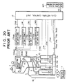
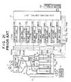
- FIGS. 20 and 21 illustrate two types of conventional coin return control systems.
- a coin deposited into a coin inlet 1 is guided along a coin guide path 2, and tested by a coin testing means 3 to determine its authenticity and type during its passage through the coin guide path.
- a coin determined to be an unacceptable coin is distributed to a first coin path 5 by a distributing gate means 4 and returned through a slug chute 10 to a return opening 11.
- a deposited coin When a deposited coin is an acceptable coin, and when it is determined to be a five hundred monetary unit coin, it is distributed to a second coin path 6; when it is determined to be a ten unit coin, it is distributed to a third coin path 7; when it is determined to be a fifty unit coin, it is distributed to a fourth coin path 8; and when it is determined to be a one hundred unit coin, it is distributed to a fifth coin path 9, respectively.
- the deposited coins thus distributed are guided through respective coin paths 6, 7, 8 and 9 and retained in a change retaining tube 12 for five hundred unit coins, a change retaining tube 13 for ten unit coins, a change retaining tube 14 for fifty unit coins and a change retaining tube 15 for one hundred unit coins, respectively.
- the determining signal DS500 which represents the determination of five hundred unit coin is input to a deposited coin number counter CT500 for five hundred unit coins; the determining signal DS10 which represents the determination of ten unit coin is input to a deposited coin number counter CT10 for ten unit coins; the determining signal DS50 which represents the determination of fifty unit coin is input to a deposited coin number counter CT50 and the determining signal DS100 which represents the determination of one hundred unit coin is input to a deposited coin number counter CT100, respectively.
- the number of deposited coins in accordance with the type of the deposited coins is counted by each of deposited coin number counters CT500, CT10, CT50 and CT100.
- the determining signals DS500, DS10, DS50 and DS100 are also input to a stored coin number counter MS500 for five hundred unit coins, a stored coin number counter MS10 for ten unit coins, a stored coin number counter MS50 for fifty unit coins and a stored coin number counter MS100 for one hundred unit coins, respectively.
- the counted numbers are added to predetermined initial values (preset values) in stored coin number counters MS500, MS10, MS50 and MS100, respectively.
- Stored coin number counters MS500, MS10, MS50 and MS100 are preset to respective predetermined initial values by input of change running-out detecting signals E500, E10, E50 and E100 sent from change running-out detecting means 12a, 13a, 14a and 15a provided on respective change retaining tubes 12, 13, 14 and 15.
- change running-out detecting means 12a for five hundred unit coins detects the change running-out state when the number of five hundred unit coins retained in change retaining tube 12 reaches two, and stored coin number counter MS500 is set to the preset value "2".
- Change running-out detecting means 13a for ten unit coins detects the change running-out state when the number of ten unit coins retained in change retaining tube 13 reaches twelve, and stored coin number counter MS10 is set to the preset value "12".
- Change running-out detecting means 14a and 15a for fifty unit coins and one hundred unit coins detect the respective change running-out states when the number of either the fifty unit coins or the one hundred unit coins retained in change retaining tubes 14 and 15 reach ten, and respective stored coin number counters MS50 and MS100 are set to the preset value "10".
- a return signal RS for deposited coins generated by a return signal generating means 100 (for example, a coin return lever) is input to a coin return control unit 17, the coin return control unit outputs paying-out signals P500, P10, P50 and P100 to a coin paying-out mechanism 16 according to counting signals C500, C10, C50 and C100 which represent counted numbers of respective deposited coin number counters CT500, CT10, CT50 and CT100 and detecting signals E500, E10, E50 and E100 of respective change running-out detecting means 12a, 13a, 14a and 15a (FIG.
- Coin paying-out mechanism 16 returns coins, which are the same type and number as the type and number of the deposited coins, from respective change retaining tubes 12, 13, 14 and 15.
- the paying-out signals P500, P10, P50 and P100 are also input to corresponding stored coin number counters MS500, MS10, MS50 and MS100, respectively.
- Respective stored coin number counters MS500, MS10, MS50 and MS100 subtract the corresponding paying-out number from the stored number when paying-out signals P500, P10, P50 and P100 are input, and then, count the present number of the coins retained in respective change retaining tubes 12, 13, 14 and 15, and hold the present counted numbers.
- a conventional coin return control system wherein coins are returned by a minimum number of coins is known. For example, when twelve ten unit coins are deposited, the system returns a one hundred unit coin and two ten unit coins.
- GB-A-1,566,201 discloses a control system for a vending machine which memorises the respective total of values of accumulated coins of each different denomination, and endeavours to issue change in the highest denomination coins possible.
- GB-A-2,140,954 discloses a vending machine having respective coin tubes for coins of different denominations; means for determining that a tube contains its permitted maximum and deflecting further coins; and means for determining that a tube contains its permitted minimum and inhibiting the paying out of coins.
- GB-A-2,140,187 discloses a vending machine having plural change tubes for coins of respective plural denominations, means for monitoring the tube contents, and an escrow for holding mixed coins. If the tube contents are insufficient for returning coins, then the escrow is usable.
- a first coin return control system comprises: coin testing means for testing the authenticity and type of deposited coins including relatively smaller denomination coins and relatively larger denomination coins; a plurality of deposited coin counter means responsive to said coin testing means whereof there is a respective one for counting the number of each type of deposited coin; a plurality of change retaining means for retaining each type of deposited coin; coin paying-out means for paying out coins from said change retaining means according to paying-out signals; a plurality of change running-out detecting means each corresponding to a particular type of coin, for detecting whether the number of coins retained in particular change retaining means is greater than a predetermined number and for generating a change running-out detecting signal when the number of coins reaches this predetermined number; and return signal generating means for generating a coin return signal for returning deposited coins, characterised in that said coin return control system further comprises comparison means for comparing a first value corresponding to the number of coins of a first type of relatively small denomination counted by a corresponding deposited coin counter with
- a second coin return control system comprises: a coin testing means for testing the authenticity and type of deposited coins including relatively smaller denomination coins and relatively larger denomination coins; a plurality of deposited coin counter means responsive to said coin testing means whereof there is a respective one for counting the number of each type of deposited coin; a plurality of change retaining means for retaining each type of deposited coin; a coin paying-out means for paying out coins from said change retaining means according to paying-out signals; a plurality of change running-out detecting means, each corresponding to a particular type of coin, for detecting whether the number of coins retained in particular change retaining means is greater than a predetermined number and for generating a change running-out detecting signal when the number of coins reaches this predetermined number; a plurality of stored coin counter means responsive to said coin testing means each of which is set to a predetermined initial value based on a signal from a corresponding change running-out detecting means, for adding the number of coins deposited into a corresponding change retaining means to
- a third coin return control system comprises: coin testing means for testing the authenticity and type of deposited coins including relatively smaller denomination coins and relatively larger denomination coins; a plurality of deposited coin counter means responsive to said coin testing means whereof there is a respective one for counting the number of each type of deposited coin; a plurality of change retaining means for retaining each type of deposited coin; coin paying-out means for paying out coins from said change retaining means according to paying-out signals; a plurality of change running-out detecting means each corresponding to a particular type of coin, for detecting whether the number of coins retained in particular change retaining means is greater than a predetermined number and for generating a change running-out detecting signal when the number of coins reaches this predetermined number; a plurality of stored coin counter means responsive to said coin testing means each of which is set to a predetermined initial value based on a signal from a corresponding change running-out detecting means, for adding the number of coins deposited into a corresponding change retaining means to a prior number of coins
- the change running-out state of the smaller denomination coin which is more frequently utilized as change can be certainly canceled by the substitution of the larger denomination coin for the smaller denomination coins, thereby increasing the chance of a sale by the vending machine. Moreover, since the above substitution is performed only when the specific condition is satisfied, the number of cases that result in the vending machine being used as a coin exchange machine can be decreased.
- the stored coin number counters are provided and the first and second control signals by the first and second comparison means are used for the coin return control by the coin return control unit.
- change running-out memory means are further provided, and the change running-out state of each type of coin is memorized.
- this state is memorized by the corresponding change running-out memory means.
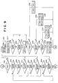
- FIG. 1 is a schematic view of a coin return control system according to a first embodiment of the present invention.
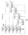
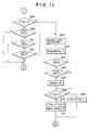
- FIGS. 2 to 6 are flowcharts of the control system of FIG. 1.
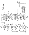
- FIG. 7 is a schematic view of a coin return control system according to a second embodiment of the present invention.
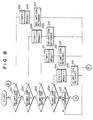
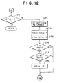
- FIGS. 8 to 12 are flowcharts of the control system of FIG. 7.
- FIG. 13 is a schematic view of a coin return control system according to a third embodiment of the present invention.
- FIGS. 14 to 19 are flowcharts of the control system of FIG. 13.
- FIG. 20 is a schematic view of a conventional coin return control system.
- FIG. 21 is a schematic view of another conventional coin return control system.
- FIGS. 1-6 illustrate a first embodiment of the present invention.
- elements corresponding to elements of the conventional coin return control system shown in FIG. 20 are identified by the same symbols as those in FIG. 20.
- Coins deposited into a coin inlet 1 are guided along a coin guide path 2, and a coin testing means 3 determines the authenticity and type of the deposited coins during their passage through the coin guide path.
- Coins determined to be unacceptable coins by coin testing means 3 are distributed to a first coin path 5 by a distributing gate means 4 and returned through a slug chute 10 to a return opening 11.
- Coins determined to be acceptable coins by coin testing means 3 are distributed to a second coin path 6, a third coin path 7, a fourth coin path 8 and a fifth coin path 9 by distributing gate means 4, respectively, in accordance with the type of coins.
- the coins from respective coin paths 6, 7, 8 and 9 are guided to and retained in corresponding change retaining tube 12 for five hundred unit coins, change retaining tube 13 for ten unit coins, change retaining tube 14 for fifty unit coins and change retaining tube 15 for one hundred unit coins each of which communicate with a coin paying-out mechanism 16.
- a change running-out detecting means 12a provided on change retaining tube 12 detects the change running-out state of the five hundred unit coins retained in the tube and outputs a detecting signal E500 when the number of the retained coins reaches two for example.
- a change running-out detecting means 13a provided on change retaining tube 13 detects the change running-out state of the ten unit coins retained in that tube and outputs a detecting signal E10 when the number of the retained coins reaches twelve.
- Change running-out detecting means 14a and 15a provided on change retaining tubes 14 and 15 detect the change running-out states of the fifty unit coins and the one hundred unit coins retained in those tubes, respectively, and output detecting signals E50 and E100 when the number of either type of coin retained in the corresponding tube reaches ten.
- Coin paying-out mechanism 16 pays out coins from change retaining tubes 12, 13, 14 and 15 to return opening 11 under control of paying-out signals P500, P10, P50 and P100 sent from a coin return control unit 50.
- a deposited coin number counter CT500 for five hundred unit coins counts the number of deposited five hundred unit coins by input of determining signals DS500 from coin testing means 3, and subtracts a number from the counted number by input of a subtraction signal CD500 from coin return control unit 50.
- a deposited coin number counter CT10 for ten unit coins counts the number of deposited ten unit coins by input of determining signals DS10 from coin testing means 3, and subtracts a number from the counted number by input of a subtraction signal CD10 from coin return control unit 50.
- a deposited coin number counter CT50 for fifty unit coins counts the number of deposited fifty unit coins by input of determining signals DS50 from coin testing means 3, and subtracts a number from the counted number by input of a subtraction signal CD50 from coin return control unit 50.
- a deposited coin number counter CT100 for one hundred unit coins counts the number of deposited one hundred unit coins by input of determining signals DS100 from coin testing means 3, and subtracts a number from the counted number by input of a subtraction signal CD100 from coin return control unit 50.
- a comparison means 20 compares counting signals C10, C50 and C100 which represent the counted numbers of respective deposited coin number counters CT10, CT50 and CT100 with the threshold numbers of the respective smaller denomination coins corresponding to denominations of respective larger denomination coins, and outputs control signals if the respective counted numbers are not less than the corresponding threshold numbers.
- a comparator 21a compares counting signal C10 representing the counted number of deposited coins by counter CT10 for ten unit coins with a threshold number TH1050 (e.g. 50, the number of ten unit coins corresponding to the denomination of a five hundred unit coin), and outputs a control signal CM1050 if C10 is not less than threshold number of 50.
- a comparator 21b compares counting signal C10 with a threshold number TH1010 (e.g. 10, the number of ten unit coins corresponding to the denomination of a one hundred unit coin), and outputs a control signal CM1010 if C10 is not less than the threshold number of 10.
- a comparator 21c compares counting signal C10 with a threshold number TH105 (e.g. 5, the number of ten unit coins corresponding to the denomination of a fifty unit coin), and outputs a control signal CM105 if C10 is not less than the threshold number of 5.
- a comparator 22a compares counting signal C50 representing the counted number of deposited coin number counter CT50 for fifty unit coins with a threshold number TH5010 (e.g. 10, the number of fifty unit coins corresponding to the denomination of a five hundred unit coin), and outputs a control signal CM5010 if C50 is not less than the threshold number of 10.
- a comparator 22b compares counting signal C50 with a threshold number TH502 (e.g. 2, the number of fifty unit coins corresponding to the denomination of a one hundred unit coin), and outputs a control signal CM502 if C50 is not less than the threshold number of 2.
- a comparator 23 compares counting signal C100 representing the counted number of deposited coin number counter CT100 for one hundred unit coins with a threshold number TH1005 (e.g. 5, the number of one hundred unit coins corresponding to the denomination of a five hundred unit coin), and outputs a control signal CM1005 if C100 is not less than the threshold number of 5.
- a threshold number TH1005 e.g. 5, the number of one hundred unit coins corresponding to the denomination of a five hundred unit coin
- a coin return control unit 50 sets paying-out signals P500, P10, P50 and P100 representing the numbers of the respective types of coins to be paid out (returned) in accordance with input of detecting signals E500, E10, E50 and E100 of change running-out detecting means 12a, 13a, 14a and 15a and counting signals C500, C10, C50 and C100 by deposited coin number counters CT500, CT10, CT50 and CT100, respectively, when return signal RS is input into the unit from a return signal generating means 100.
- Control unit 50 outputs subtraction signal CD500 to deposited coin number counter CT500, subtraction signal CD10 to deposited coin number counter CT10, subtraction signal CD50 to deposited coin number counter CT50 and subtraction signal CD100 to deposited coin number counter CT100, respectively. Further, coin return control unit 50 sets paying-out signals P500, P10, P50 and P100 so as to pay out (return) relatively larger denomination coins instead of the relatively smaller denomination coins if, when return signal RS is input, at least one of detecting signals E10, E50 and E100 of change running-out detecting means 13a, 14a and 15a is input, at least one of control signals CM1050, CM1010, CM105, CM5010, CM502 and CM1005 of comparators 21a, 21b, 21c, 22a, 22b and 23 is input; one or more of the detecting signal E500, E50 or E100 is not input; and outputs the paying-out signals to coin paying-out mechanism 16.
- step 101-104 it is determined by coin testing means 3 whether each of five hundred unit coins, one hundred unit coins, fifty unit coins and ten unit coins is deposited (steps 101-104). If the deposited coin is determined to be a five hundred unit coin at step 101, determining signal DS500 is input to deposited coin number counter CT500 for five hundred unit coins and the count in counter CT500 is incremented by one (step 105). The five hundred unit coin is distributed to second coin path 6 by distributing gate means 4 and sent to and retained in change retaining tube 12 for five hundred unit coins (step 106), and control returns to step 101.
- determining signal DS100 is input to deposited coin number counter CT100 for one hundred unit coins and the count in that counter is incremented by one (step 107).
- the one hundred unit coin is distributed to fifth coin path 9 by distributing gate means 4 and sent to and retained in change retaining tube 15 for one hundred unit coins (step 108), and control returns to step 101.
- determining signal DS50 is input to deposited coin number counter CT50 for fifty unit coins and the count in that counter is incremented by one (step 109).
- the fifty unit coin is distributed to fourth coin path 8 by distributing gate means 4 and sent to and retained in change retaining tube 14 for fifty unit coins (step 110), and control returns to step 101.
- determining signal DS10 is input to deposited coin number counter CT10 for ten unit coins and the count in that counter is incremented by one (step 111).
- the ten unit coin is distributed to third coin path 7 by distributing gate means 4 and sent to and retained in change retaining tube 13 for ten unit coins (step 112), and control returns to step 101.
- coin return control unit 50 determines whether return signal RS is generated by operation of return signal generating means 100 (step 113). If return signal RS is generated, control proceeds to the coin return control portion of the flow diagram as shown in FIGS. 3-6.
- Coin return control unit 50 determines by counting signal C500 for five hundred unit coins whether the counted number of the deposited coin number counter is zero (step 114). If the counted number is determined to be zero at step 114, it is determined whether detecting signal E500 of change running-out detecting means 12a for five hundred unit coins is input (step 115). If it is determined at step 115 that detecting signal E500 is not input, it is determined whether detecting signal E100 of change running-out detecting means 15a for one hundred unit coins is input (step 116).
- coin return control unit 50 outputs paying-out signal P500 to coin paying-out mechanism 16.
- P500 a five hundred unit coin is returned from five hundred unit coin retaining tube 12 to return opening 11 (step 122).
- step 123 it is determined whether the counted number of deposited coin number counter CT500 for five hundred unit coins is zero. If the counted number is determined not to be zero, subtraction signal CD500 is output to deposited coin number counter CT500 to subtract one from the count. This causes deposited coin number counter CT500 to be decremented by one (step 124), and control returns to step 114.
- step 125 it is determined whether control signal CM1005 is input. If control signal CM1005 is input, subtraction signal CD100 is output to deposited coin number counter CT100 to subtract five from the counted number. This causes deposited coin number counter CT100 to be decremented by five (step 126), and control returns to step 114.
- control signal CM1005 is determined not to be input at step 125, it is determined whether control signal CM5010 is input (step 127). If control signal CM5010 is input, subtraction signal CD50 is output to deposited coin number counter CT50 to subtract ten from the counted number. This causes deposited coin number counter CT50 to be decremented by ten (step 128), and control returns to step 114.
- control signal CM5010 is determined not to be input at step 127, subtraction signal CD10 is output to deposited coin number counter CT10 to subtract fifty from the counted number. This causes deposited coin number counter CT10 to be decremented by fifty (step 129), and control returns to step 114.
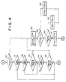
- step 115 If it is determined that detecting signal E500 is input at step 115, that detecting signal E10 is not input at step 120, or that control signal CM1050 is not input at step 121, control proceeds to the operation shown in FIG. 4 beginning with step 130.
- Coin return control unit 50 determines whether the counted number of deposited coin number counter CT100 is zero or not, by counting signal C100 of the deposited coin number counter (step 130). If the counted number is determined to be zero at step 130, it is determined whether detecting signal E100 of change running-out detecting means 15a for one hundred unit coins is input (step 131). If detecting signal E100 is not input at step 131, it is determined whether detecting signal E50 of change running-out detecting means 14a for fifty unit coins is input (step 132).
- control signal CM1010 is not input at step 135, that detecting signal E100 is input at step 131, or that detecting signal E10 is not input at step 134, control proceeds to the operation shown in FIG. 5 beginning at step 142.
- coin return control unit 50 outputs paying-out signal P100 to coin paying-out mechanism 16. According to this P100 signal, a one hundred unit coin is returned from one hundred unit coin retaining tube 15 to return opening 11 (step 136).
- step 137 it is determined whether the counted number of deposited coin number counter CT100 for one hundred unit coins is zero. If the counted number is determined not to be zero, subtraction signal CD100 is output to deposited coin number counter CT100 to subtract one from the counted number. This causes deposited coin number counter CT100 to be decremented by one (step 138), and control returns to step 114 shown in FIG. 3.
- step 139 If the counted number of deposited coin number counter CT100 is determined to be zero at step 137, it is determined whether control signal CM502 is input (step 139). If control signal CM502 is input, subtraction signal CD50 is output to deposited coin number counter CT50 to subtract two from the counted number. This causes deposited coin number counter CT50 to be decremented by two (step 140), and control returns to step 114.
- control signal CM502 is determined not to be input at step 139, subtraction signal CD10 is output to deposited coin number counter CT10 to subtract ten from the counted number. This causes deposited coin number counter CT10 to be decremented by ten (step 141), and control returns to step 114.
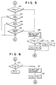
- coin return control unit 50 determines whether the counted number of deposited coin number counter CT50 is zero or not, based on counting signal C50 of the deposited coin number counter (step 142).
- step 142 If the counted number is determined to be zero at step 142, it is determined whether detecting signal E50 of change running-out detecting means 14a for fifty unit coins is input (step 143). If detecting signal E50 is determined not to be input at step 143, it is determined whether detecting signal E10 of change running-out detecting means 13a for ten unit coins is input (step 144).
- step 143 If it is determined that detecting signal E50 is input at step 143, that detecting signal E10 is not input at step 144, or that control signal CM105 is not input at step 145, control proceeds to the operation shown in FIG. 6 beginning at step 150.
- coin return control unit 50 outputs paying-out signal P50 to coin paying-out mechanism 16. According to this P50 signal, a fifty unit coin is returned from fifty unit coin retaining tube 14 to return opening 11 (step 146).
- step 147 it is determined whether the counted number of deposited coin number counter CT50 for fifty unit coins is zero. If the counted number is determined not to be zero, subtraction signal CD50 is output to deposited coin number counter CT50 to subtract one from the counted number. This causes deposited coin number counter CT50 to be decremented by one (step 148), and control returns to step 114 shown in FIG. 3.
- step 147 If the counted number of deposited coin number counter CT50 is determined to be zero at step 147, subtraction signal CD10 is output to deposited coin number counter CT10 to subtract five from the counted number. This causes deposited coin number counter CT10 to be decremented by five (step 149), and control returns to step 114.
- coin return control unit 50 determines whether the counted number of deposited coin number counter CT10 is zero or not, based on counting signal C10 of the deposited coin number counter CT10 (step 150). If the counted number of deposited coin number counter CT10 is determined not to be zero at step 150, coin return control unit 50 outputs paying-out signal P10 to coin paying-out mechanism 16 and subtraction signal CD10 to deposited coin number counter CT10. A ten unit coin is returned from ten unit coin retaining tube 13 to return opening 11 according to paying-out signal P10 (step 151) and the counted number of deposited coin number counter CT10 is decremented by one (step 152), and control returns to step 114 shown in FIG. 3.
- step 150 if it is determined at step 150 that the counted number is zero, the operation of the above coin return control is finished.
- FIGS. 7-12 illustrate a second embodiment of the present invention.
- the system according to this embodiment further comprises stored coin number counters MS500, MS10, MS50 and MS100 and a second comparison means 30.
- Stored coin number counter MS500 for five hundred unit coins is set to a predetermined initial value, e.g.”2" by input of detecting signal E500 of change running-out detecting means 12a, adds the number of five hundred unit coins deposited into change retaining tube 12 to the prior number of the coins retained in the tube by input of determining signals DS500 of coin testing means 3, subtracts the number of the coins paid out from the tube by input of paying-out signal P500 (described later), and adds a number to the prior number by input of addition signal MU500 (described later).
- Stored coin number counter MS10 for ten unit coins is set to a predetermined initial value e.g.”12" by input of detecting signal E10 of change running-out detecting means 13a, adds the number of ten unit coins deposited into change retaining tube 13 to the prior number of the coins retained in the tube by input of determining signals DS10 of coin testing means 3, subtracts the number of the coins paid out from the tube by input of paying-out signal P10 (described later), and adds a number to the prior number by input of addition signal MU10 (described later).
- Stored coin number counter MS50 for fifty unit coins is set to a predetermined initial value e.g.”10" by input of detecting signal E50 of change running-out detecting means 14a, adds the number of fifty unit coins deposited into change retaining tube 14 to the prior number of the coins retained in the tube by input of determining signals DS50 of coin testing means 3, subtracts the number of the coins paid out from the tube by input of paying-out signal P50 (described later), and adds a number to the prior number by input of a addition signal MU50 (described later).
- Stored coin number counter MS100 for one hundred unit coins is set to a predetermined initial value e.g.”10" by input of detecting signal E100 of change running-out detecting means 15a, adds the number of one hundred unit coins deposited into change retaining tube 15 to the prior number of the coins retained in the tube by input of determining signals DS100 of coin testing means 3, subtracts the number of the coins paid out from the tube by input of paying-out signal P100 (described later), and adds a number to the prior number by input of a addition signal MU100 (described later).
- Second comparison means 30 compares counting signals M500, M10, M50 and M100 which represent the counted numbers of respective stored coin number counters MS500, MS10, MS50 and MS100 with the corresponding predetermined initial values (preset values; e.g.”2", “12", “10” and “10") for the respective stored coin number counters, and outputs second control signals if the respective counted numbers are greater than the corresponding predetermined initial values.
- predetermined initial values preset values
- a coin return control unit 60 sets paying-out signals P500, P10, P50 and P100 representing the numbers of the respective types of coins to be paid out (to be returned) in accordance with input of detecting signals E500, E10, E50 and E100 by change running-out detecting means 12a, 13a, 14a and 15a, counting signals C500, C10, C50 and C100 by deposited coin number counters CT500, CT10, CT50 and CT100 and stored number counting signals M500, M10, M50 and M100 by stored coin number counters MS500, MS10, MS50 and MS100, respectively, when return signal RS from a return signal generating means 100 is input to the unit, and outputs the paying-out signals to coin paying-out mechanism 16.
- coin return control unit 60 outputs paying-out signal P500 and addition signal MU500 to stored coin number counter MS500; paying-out signal P10 and addition signal MU10 to stored coin number counter MS10; paying-out signal P50 and addition signal MU50 to stored coin number counter MS50; and paying-out signal P100 and addition signal MU100 to stored coin number counter MS100, respectively, and outputs subtraction signal CD500 to deposited coin number counter CT500, subtraction signal CD10 to deposited coin number counter CT10, subtraction signal CD50 to deposited coin number counter CT50 and subtraction signal CD100 to deposited coin number counter CT100, respectively.
- coin return control unit 60 sets paying-out signals P500, P10, P50 and P100 to pay out (return) relatively larger denomination coins instead of the relatively smaller denomination coins if, when return signal RS is input, at least one of detecting signals E10, E50 and E100 of change running-out detecting means 13a, 14a and 15a is input, at least one of first control signals CM1050, CM1010, CM105, CM5010, CM502 and CM1005 from comparators 21a, 21b, 21c, 22a, 22b and 23 is input and second control signal CP500, CP10, CP50 or CP100 of comparator 31, 32, 33 or 34 is input, and outputs the paying-out signals to coin paying-out mechanism 16 and stored coin number counters MS500, MS10, MS50 and MS100.
- the determination of the type of deposited coins by coin testing means 3 is substantially the same as in the flow shown in FIG. 2 (steps 201-204).
- Determining signal DS500 for a five hundred unit coin is input to deposited coin number counter CT500 and stored coin number counter MS500, and the counters are each incremented by one (steps 205 and 206).
- the deposited five hundred unit coin is sent to change retaining tube 12 for five hundred unit coins (step 207).
- Determining signal DS100 for a one hundred unit coin is input to deposited coin number counter CT100 and stored coin number counter MS100, and the counters are each incremented by one (steps 208 and 209).
- the deposited one hundred unit coin is sent to change retaining tube 15 for one hundred unit coins (step 210).
- Determining signal DS50 for a fifty unit coin is input to deposited coin number counter CT50 and stored coin number counter MS50, and the counters are each incremented by one (steps 211 and 212).
- the deposited fifty unit coin is sent to change retaining tube 14 for fifty unit coins (step 213).
- Determining signal DS10 for a ten unit coin is input to deposited coin number counter CT10 and stored coin number counter MS10, and the counters are each incremented by one (steps 214 and 215).
- the deposited ten unit coin is sent to change retaining tube 13 for ten unit coins (step 216). Control returns from step 207, 210, 213 or 216 to step 201.
- coin return control unit 60 determines whether return signal RS is generated by operation of return signal generating means 100 (step 217). If return signal RS is generated, control proceeds to the coin return control shown in FIGS. 9-12.
- Coin return control unit 60 determines by counting signal C500 of deposited coin number counter CT500 for five hundred unit coins whether the counted number of the deposited coin number counter is zero (step 218). If the counted number is determined to be zero at step 218, it is determined whether the counted number of stored coin number counter MS500 for five hundred unit coins is greater than the predetermined initial value "2" and therefore that second control signal CP500 of comparator 31 of second comparison means 30 is input (step 219). If it is determined at step 219 that second control signal CP500 is input, it is determined whether detecting signal E100 of change running-out detecting means 15a for one hundred unit coins is input (step 220).
- coin return control unit 60 outputs paying-out signal P500 to coin paying-out mechanism 16 and stored coin number counter MS500.
- P500 signal a five hundred unit coin is returned from change retaining tube 12 for five hundred unit coins to return opening 11 (step 226), and the counted number of stored coin number counter MS500 is decremented by one (step 227).
- coin return control unit 60 determines whether detecting signal E500 of change running-out detecting means 12a is input (step 228). If detecting signal E500 is determined to be input at step 228, it is determined whether second control signal CP500 of comparator 31 of second comparison means 30 is input (step 229). If the second control signal CP500 is input, the counted number of stored coin number counter MS500 is determined to be "2" (step 230).
- step 230 After the determination at step 230, or if it is determined that detecting signal E500 is not input at step 228 or that second control signal CP500 is not input at step 229, it is determined whether the counted number of deposited coin number counter CT500 for five hundred unit coins is zero (step 231). If the counted number is not zero, subtraction signal CD500 is output to deposited coin number counter CT500 so as to subtract one from the counted number. This causes deposited coin number counter CT500 to be decremented by one (step 232), and control returns to step 218.
- step 233 it is determined whether first control signal CM1005 is input. If first control signal CM1005 is input, subtraction signal CD100 is output to deposited coin number counter CT100 to subtract five from its counted number, and addition signal MU100 is output to stored coin number counter MS100 to add five to its counted number. This causes deposited coin number counter CT100 to be decremented by five (step 234) and stored coin number counter MS100 to be incremented by five (step 235), and control returns to step 218.
- first control signal CM1005 is determined not to be input at step 233, it is determined whether first control signal CM5010 is input (step 236). If first control signal CM5010 is input, subtraction signal CD50 is output to deposited coin number counter CT50 to subtract ten from its counted number, and addition signal MU50 is output to stored coin number counter MS50 to add ten to its counted number. This causes deposited coin number counter CT50 to be decremented by ten (step 237) and stored coin number counter MS50 to be incremented by ten (step 238), and control returns to step 218.
- first control signal CM5010 is determined not to be input at step 236, subtraction signal CD10 is output to deposited coin number counter CT10 to subtract fifty from its counted number, and addition signal MU10 is output to stored coin number counter MS10 to add fifty to its counted number. This causes deposited coin number counter CT10 to be decremented by fifty (step 239) and stored coin number counter MS10 to be incremented by fifty (step 240), and control returns to step 218.
- control proceeds to the operation shown in FIG. 10.
- coin return control unit 60 determines whether the counted number of deposited coin number counter CT100 is zero or not, by counting signal C100 of the deposited coin number counter (step 241). If the counted number is determined to be zero at step 241, it is determined whether the counted number of stored coin number counter MS100 for one hundred unit coins is greater than its predetermined initial value and therefore that second control signal CP100 of comparator 34 of second comparison means 30 is input (step 242). If second control signal CP100 is determined to be input at step 242, it is determined whether detecting signal E50 of change running-out detecting means 14a for fifty unit coins is input (step 243).
- control proceeds to the operation shown in FIG. 11.
- coin return control unit 60 outputs paying-out signal P100 to coin paying-out mechanism 16 and stored coin number counter MS100.
- P100 a one hundred unit coin is returned from change retaining tube 15 for one hundred unit coins to return opening 11 (step 247), and the counted number of stored coin number counter MS100 is decremented by one (step 248).
- coin return control unit 60 determines whether detecting signal E100 of change running-out detecting means 15a is input (step 249). If detecting signal E100 is determined to be input at step 249, it is determined whether second control signal CP100 of comparator 34 of second comparison means 30 is input (step 250). If the second control signal CP100 is input, the counted number of stored coin number counter MS100 is determined to be "10" (step 251).
- step 252 After the determination at step 251, or if it is determined that detecting signal E100 is not input at step 249 or that second control signal CP100 is not input at step 250, it is determined whether the counted number of deposited coin number counter CT100 for one hundred unit coins is zero (step 252). If the counted number is not zero, subtraction signal CD100 is output to deposited coin number counter CT100 to subtract one from the counted number. This causes deposited coin number counter CT100 to be decremented by one (step 253), and control returns to step 218.
- step 254 it is determined whether first control signal CM502 is input (step 254). If first control signal CM502 is input, subtraction signal CD50 is output to deposited coin number counter CT50 to subtract two from its counted number, and addition signal MU50 is output to stored coin number counter MS50 to add two to its counted number. This causes deposited coin number counter CT50 to be decremented by two (step 255) and stored coin number counter MS50 to be incremented by two (step 256), and control returns to step 218.
- first control signal CM502 is determined not to be input at step 254
- subtraction signal CD10 is output to deposited coin number counter CT10 to subtract ten from its counted number
- addition signal MU10 is output to stored coin number counter MS10 to add ten to its counted number. This causes deposited coin number counter CT10 to be decremented by ten (step 257) and stored coin number counter MS10 to be incremented by ten (step 258), and control returns to step 218.
- coin return control unit 60 determines whether the counted number of deposited coin number counter CT50 is zero or not, based on counting signal C50 of the deposited coin number counter (step 259). If the counted number is determined to be zero at step 259, it is determined whether the counted number of stored coin number counter MS50 for fifty unit coins is greater than its predetermined initial value and therefore that second control signal CP50 of comparator 33 of second comparison means 30 is input (step 260). If second control signal CP50 is determined to be input at step 260, it is determined whether detecting signal E10 of change running-out detecting means 13a for ten unit coins is input (step 261).
- detecting signal E10 is determined to be input at step 261
- it is determined whether the counted number of deposited coin number counter CT10 for ten unit coins is not less than threshold value TH105 ( 5) and therefore that first control signal CM105 of comparator 21c of first comparison means 20 is input (step 262).
- coin return control unit 60 outputs paying-out signal P50 to coin paying-out mechanism 16 and stored coin number counter MS50.
- P50 a fifty unit coin is returned from change retaining tube 14 for fifty unit coins to return opening 11 (step 263), and the counted number of stored coin number counter MS50 is decremented by one (step 264).
- coin return control unit 60 determines whether detecting signal E50 of change running-out detecting means 14a is input (step 265). If detecting signal E50 is determined to be input at step 265, it is determined whether second control signal CP50 of comparator 33 of second comparison means 30 is input (step 266). If the second control signal CP50 is input, the counted number of stored coin number counter MS50 is determined to be "10" (step 267).
- step 267 After the determination at step 267, or if it is determined that detecting signal E50 is not input at step 265 or that second control signal CP50 is not input at step 266, it is determined whether the counted number of deposited coin number counter CT50 for fifty unit coins is zero (step 268). If the counted number is not zero, subtraction signal CD50 is output to deposited coin number counter CT50 to subtract one from the counted number. This causes deposited coin number counter CT50 to be decremented by one (step 269), and control returns to step 218.
- step 268 If the counted number of deposited coin number counter CT50 is determined to be zero at step 268, subtraction signal CD10 is output to deposited coin number counter CT10 to subtract five from its counted number, and addition signal MU10 is output to stored coin number counter MS10 to add five to its counted number. This causes deposited coin number counter CT10 to be decremented by five (step 270) and stored coin number counter MS10 to be incremented by five (step 271), and control returns to step 218.
- coin return control unit 60 determines whether the counted number of deposited coin number counter CT10 is zero or not, based on counting signal C10 of the deposited coin number counter CT10 (step 272). If the counted number is determined not to be zero at step 272, coin return control unit 60 outputs paying-out signal P10 to coin paying-out mechanism 16 and stored coin number counter MS10 and outputs subtraction signal CD10 to deposited coin number counter CT10. According to this P10 signal, a ten unit coin is returned from change retaining tube 13 for ten unit coins to return opening 11 (step 273), and the counted number of stored coin number counter MS10 is decremented by one (step 264) and deposited coin number counter CT10 is also decremented by one (step 275).
- coin return control unit 60 determines whether detecting signal E10 of change running-out detecting means 13a is input (step 276). If detecting signal E10 is determined to be input at step 276, it is determined whether second control signal CP10 of comparator 32 of second comparison means 30 is input (step 277). If the second control signal CP10 is input, the counted number of stored coin number counter MS10 is determined to be "12" (step 278).
- step 278 After the determination at step 278, or if it is determined that detecting signal E10 is not input at step 276, control returns to step 218 shown in FIG. 9.
- the relatively larger denomination coin is adequately returned instead of the smaller denomination coins, only when the smaller denomination coin is in its change running-out state. Therefore, the chance for a vending machine sale can be increased, and the use of the vending machine as a coin exchange machine can be adequately prevented.
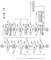
- FIGS. 13-19 illustrate a third embodiment of the present invention.
- the system according to this embodiment further comprises change running-out memory means EMP500, EMP10, EMP50 and EMP100 and a memory signal generation means 40, as compared with the second embodiment.
- Other elements in FIG. 13 are basically the same as those in FIG. 7, other than control by a coin return control unit 70.
- Counting signals C500, C10, C50 and C100 of deposited coin number counters CT500, CT10, CT50 and CT100 are input to memory signal generation means 40, and the memory signal generation means outputs a memory signal ST only when all the counted numbers of deposited coin number counters CT500, CT10, CT50 and CT100 are zero (initial value).
- Detecting signal E500 of change running-out detecting means 12a for five hundred unit coins is input to change running-out memory means EMP500.
- Change running-out memory means EMP500 sets its flag F500 to "1” by input of detecting signal E500 and memory signal ST, and sets the flag to "0" if the detecting signal is not input when the memory signal is input.
- Detecting signal E10 of change running-out detecting means 13a for ten unit coins is input to change running-out memory means EMP10.
- Change running-out memory means E10 sets its flag F10 to "1” by input of detecting signal E10 and memory signal ST, and sets the flag to "0" if the detecting signal is not input when the memory signal is input.
- Detecting signal E50 of change running-out detecting means 14a for fifty unit coins is input to change running-out memory means EMP50.
- Change running-out memory means EMP50 sets its flag F50 to "1” by input of detecting signal E50 and memory signal ST, and sets the flag to "0" if the detecting signal is not input when the memory signal is input.
- Detecting signal E100 of change running-out detecting means 15a for one hundred unit coins is input to change running-out memory means EMP100.
- Change running-out memory means EMP100 sets its flag F100 to "1” by input of detecting signal E100 and memory signal ST, and sets the flag to "0" if the detecting signal is not input when the memory signal is input.
- first comparison means 20 and second comparison means 30 are substantially the same as those in the second embodiment.
- a coin return control unit 70 sets paying-out signals P500, P10, P50 and P100 representing the numbers of the respective types of coins to be paid out (to be returned) in accordance with the input of detecting signals E500, E10, E50 and E100 by change running-out detecting means 12a, 13a, 14a and 15a, counting signals C500, C10, C50 and C100 by deposited coin number counters CT500, CT10, CT50 and CT100 and stored number counting signals M500, M10, M50 and M100 by stored coin number counters MS500, MS10, MS50 and MS100, respectively, when return signal RS from a return signal generating means 100 is input to the unit, and outputs the paying-out signals to coin paying-out mechanism 16.
- coin return control unit 70 outputs paying-out signal P500 and addition signal MU500 to stored coin number counter MS500; paying-out signal P10 and addition signal MU10 to stored coin number counter MS10; paying-out signal P50 and addition signal MU50 to stored coin number counter MS50; and paying-out signal P100 and addition signal MU100 to stored coin number counter MS100, respectively, and outputs subtraction signal CD500 to deposited coin number counter CT500, subtraction signal CD10 to deposited coin number counter CT10, subtraction signal CD50 to deposited coin number counter CT50 and subtraction signal CD100 to deposited coin number counter CT100, respectively.
- coin return control unit 70 sets paying-out signals P500, P10, P50 and P100 to pay out (return) the relatively larger denomination coins instead of the relatively smaller denomination coins if, when return signal RS is input, at least one of flags F10, F50 and F100 of change running-out memory means EMP10, EMP50 and EMP100 is set to "1", at least one of first control signals CM1050, CM1010, CM105, CM5010, CM502 and CM1005 from comparators 21a, 21b, 21c, 22a, 22b and 23 is input and second control signal CP500, CP10, CP50 or CP100 of comparator 31, 32, 33 or 34 is input, and outputs the paying-out signals to coin paying-out mechanism 16 and stored coin number counters MS500, MS10, MS50 and MS100.
- first control signals CM1050, CM10, CM105, CM5010, CM502 and CM1005 from comparators 21a, 21b, 21c, 22
- Coin return control unit 70 also outputs addition signals MU500, MU10, MU50 and MU100 to corresponding stored coin number counters MS500, MS10, MS50 and MS100 and subtraction signals CD500, CD10, CD50 and CD100 to corresponding deposited coin number counters CT500, CT10, CT50 and CT100.
- step 301 shown in FIG. 14 corresponds to step 201 shown in FIG. 8, step 302 to step 202, step 303 to step 203, step 304 to step 204, step 305 to step 217, step 323 to step 205, step 324 to step 206, step 325 to step 207, step 326 to step 208, step 327 to step 209, step 328 to step 210, step 329 to step 211, step 330 to step 212, step 331 to to step 213, step 332 to step 214, step 333 to step 215 and step 334 to step 216, respectively.
- Flow proceeds to the operation shown in FIG. 15 from step 305, 325, 328, 331 or 334.
- memory signal generation means 40 determines whether each of the counted numbers of deposited coin number counters CT500, CT10, CT50 and CT100 is zero, by input counting signals C500, C10, C50 and C100 of the deposited coin number counters (steps 306-309). If the counted numbers of deposited coin number counters CT500, CT10, CT50 and CT100 are determined to be all zero at steps 306-309, memory signal generation means 40 outputs memory signal ST to change running-out memory means EMP500, EMP10, EMP50 and EMP100, respectively (step 310).
- change running-out memory means EMP500 for five hundred unit coins determines whether detecting signal E500 of change running-out detecting means 12a is input (step 311), sets its flag F500 to "1” if the detecting signal is determined to be input (step 312), and sets the flag to "0” if the detecting signal is determined not to be input (step 313).
- Change running-out memory means EMP100 for one hundred unit coins determines whether detecting signal E100 of change running-out detecting means 15a is input (step 314), sets its flag F100 to "1” if the detecting signal is determined to be input (step 315), and sets the flag to "0” if the detecting signal is determined not to be input (step 316).
- Change running-out memory means EMP50 for fifty unit coins determines whether detecting signal E50 of change running-out detecting means 14a is input (step 317), sets its flag F500 to "1" if the detecting signal is determined to be input (step 318), and sets its flag to "0” if the detecting signal is determined not to be input (step 319).
- Change running-out memory means EMP10 for ten unit coins determines whether detecting signal E10 of change running-out detecting means 13a is input (step 320), sets its flag F10 to "1” if the detecting signal is determined to be input (step 321), and sets its flag to "0” if the detecting signal is determined not to be input (step 322). After the above operation, flow returns to step 301 in FIG. 14. If the counted number of any deposited coin number counter CT500, CT10, CT50 or CT100 is determined not to be zero at step 306, 307, 308 or 309, flow also returns to step 301.
- coin return control unit 70 determines that return signal RS is generated by return signal generating means 100 when it is determined at steps 301-304 that no coins are deposited, flow proceeds to the operation shown in FIGS. 16-19.
- Coin return control unit 70 determines by counting signal C500 of deposited coin number counter CT500 for five hundred unit coins whether the counted number of the deposited coin number counter is zero (step 335). If the counted number is determined to be zero at step 335, it is determined whether the counted number of stored coin number counter MS500 for five hundred unit coins is greater than the predetermined initial value "2" and second control signal CP500 of comparator 31 of second comparison means 30 is input (step 336). If it is determined at step 336 that second control signal CP500 is input, it is determined whether flag F100 of change running-out memory means EMP100 for one hundred unit coins is set to "1" (step 337).
- coin return control unit 70 outputs paying-out signal P500 to coin paying-out mechanism 16 and stored coin number counter MS500.
- P500 signal a five hundred unit coin is returned from change retaining tube 12 for five hundred unit coins to return opening 11 (step 343), and the counted number of stored coin number counter MS500 is decremented by one (step 344).
- coin return control unit 70 determines whether detecting signal E500 of change running-out detecting means 12a is input (step 345). If detecting signal E500 is determined to be input at step 345, it is determined whether second control signal CP500 of comparator 31 of second comparison means 30 is input (step 346). If the second control signal CP500 is input, the counted number of stored coin number counter MS500 is determined to be "2" (step 347).
- step 348 it is determined whether the counted number of deposited coin number counter CT500 for five hundred unit coins is zero (step 348). If the counted number is not zero, subtraction signal CD500 is output to deposited coin number counter CT500 to subtract one from the counted number. This causes deposited coin number counter CT500 to be decremented by one (step 349), and control returns to step 335.
- step 350 it is determined whether first control signal CM1005 is input (step 350). If first control signal CM1005 is input, subtraction signal CD100 is output to deposited coin number counter CT100 to subtract five from its counted number, and addition signal MU100 is output to stored coin number counter MS100 to add five to its counted number. This causes deposited coin number counter CT100 to be decremented by five (step 351) and stored coin number counter MS100 to be incremented by five (step 352), and control returns to step 335.
- first control signal CM1005 is determined not to be input at step 350, it is determined whether first control signal CM5010 is input (step 353). If first control signal CM5010 is input, subtraction signal CD50 is output to deposited coin number counter CT50 to subtract ten from its counted number, and addition signal MU50 is output to stored coin number counter MS50 to add ten to its counted number. This causes deposited coin number counter CT50 to be decremented by ten (step 354) and stored coin number counter MS50 to be incremented by ten (step 355), and control returns to step 335.
- first control signal CM5010 is determined not to be input at step 353
- subtraction signal CD10 is output to deposited coin number counter CT10 to subtract fifty from its counted number
- addition signal MU10 is output to stored coin number counter MS10 to add fifty to its counted number. This causes deposited coin number counter CT10 to be decremented by fifty (step 356) and stored coin number counter MS10 to be incremented by fifty (step 357), and control returns to step 335.
- control proceeds to the operation shown in FIG. 17.
- coin return control unit 70 determines whether the counted number of deposited coin number counter CT100 is zero or not, based on counting signal C100 of the deposited coin number counter (step 358). If the counted number is determined to be zero at step 358, it is determined whether the counted number of stored coin number counter MS100 for one hundred unit coins is greater than its predetermined initial value and second control signal CP100 of comparator 34 of second comparison means 30 is input (step 359). If second control signal CP100 is determined to be input at step 359, it is determined whether flag F50 of change running-out memory means EMP50 for fifty unit coins is set to "1" (step 360).
- flag F50 is not set to "1" at step 360 or that first control signal CM502 is not input at step 361
- coin return control unit 70 outputs paying-out signal P100 to coin paying-out mechanism 16 and stored coin number counter MS100.
- this signal P100 a one hundred unit coin is returned from change retaining tube 15 for one hundred unit coins to return opening 11 (step 364), and the counted number of stored coin number counter MS100 is decremented by one (step 365).
- coin return control unit 70 determines whether detecting signal E100 of change running-out detecting means 15a is input (step 366). If detecting signal E100 is determined to be input at step 366, it is determined whether second control signal CP100 of comparator 34 of second comparison means 30 is input (step 367). If the second control signal CP100 is input, the counted number of stored coin number counter MS100 is determined to be "10" (step 368).
- step 368 After the determination at step 368, or if it is determined that detecting signal E100 is not input at step 366 or that second control signal CP100 is not input at step 367, it is determined whether the counted number of deposited coin number counter CT100 for one hundred unit coins is zero (step 369). If the counted number is not zero, subtraction signal CD100 is output to deposited coin number counter CT100 to subtract one from the counted number. This causes deposited coin number counter CT100 to be decremented by one (step 370), and control returns to step 335.
- step 371 If the counted number of deposited coin number counter CT100 is determined to be zero at step 369, it is determined whether first control signal CM502 is input (step 371). If first control signal CM502 is input, subtraction signal CD50 is output to deposited coin number counter CT50 to subtract two from its counted number, and addition signal MU50 is output to stored coin number counter MS50 to add two to its counted number. This causes deposited coin number counter CT50 to be decremented by two (step 372) and stored coin number counter MS50 to be incremented by two (step 373), and control returns to step 335.
- first control signal CM502 is determined not to be input at step 371, subtraction signal CD10 is output to deposited coin number counter CT10 to subtract ten from its counted number, and addition signal MU10 is output to stored coin number counter MS10 to add ten to its counted number. This causes deposited coin number counter CT10 to be decremented by ten (step 374) and stored coin number counter MS10 to be incremented by ten (step 375), and control returns to step 335.
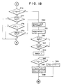
- control proceeds to the operation shown in FIG. 18.
- Coin return control unit 70 determines whether the counted number of deposited coin number counter CT50 is zero or not, by counting signal C50 of the deposited coin number counter (step 376). If the counted number is determined to be zero at (step 376, it is determined whether the counted number of stored coin number counter MS50 for fifty unit coins is greater than its predetermined initial value and second control signal CP50 of comparator 33 of second comparison means 30 is input (step 377). If second control signal CP50 is determined to be input at step 377, it is determined whether flag F10 of change running-out memory means EMP10 for ten unit coins is set to "1" (step 378).
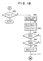
- control proceeds to the operation shown in FIG. 19.
- coin return control unit 70 outputs paying-out signal P50 to coin paying-out mechanism 16 and stored coin number counter MS50. According to this P50 signal, a fifty unit coin is returned from change retaining tube 14 for fifty unit coins to return opening 11 (step 380), and the counted number of stored coin number counter MS50 is decremented by one (step 381).
- coin return control unit 70 determines whether detecting signal E50 of change running-out detecting means 14a is input (step 382). If detecting signal E50 is determined to be input at step 392, it is determined whether second control signal CP50 of comparator 33 of second comparison means 30 is input (step 383). If the second control signal CP50 is input, the counted number of stored coin number counter MS50 is determined to be "10" (step 384).
- step 384 After the determination at step 384, or if it is determined that detecting signal E50 is not input at step 382 or that second control signal CP50 is not input at step 383, it is determined whether the counted number of deposited coin number counter CT50 for fifty unit coins is zero (step 385). If the counted number is not zero, subtraction signal CD50 is output to deposited coin number counter CT50 to subtract one from the counted number. This causes deposited coin number counter CT50 to be decremented by one (step 386), and control returns to step 385.
- step 385 If the counted number of deposited coin number counter CT50 is determined to be zero at step 385, subtraction signal CD10 is output to deposited coin number counter CT10 to subtract five from its counted number, and addition signal MU10 is output to stored coin number counter MS10 to add five to its counted number. This causes deposited coin number counter CT10 to be decremented by five (step 387) and stored coin number counter MS10 to be incremented by five (step 388), and control returns to step 335.
- coin return control unit 70 determines whether the counted number of deposited coin number counter CT10 is zero or not, based on counting signal C10 of the deposited coin number counter (step 389). If the counted number is determined to be zero at step 389, coin return control unit 70 outputs paying-out signal P10 to coin paying-out mechanism 16 and stored coin number counter MS10 and outputs subtraction signal CD10 to deposited coin number counter CT10. According to this signal P10, a ten unit coin is returned from change retaining tube 13 for ten unit coins to return opening 11 (step 390), and the counted number of stored coin number counter MS10 is decremented by one (step 391) and deposited coin number counter CT10 is also decremented by one (step 392).
- coin return control unit 70 determines whether detecting signal E10 of change running-out detecting means 13a is input (step 393). If detecting signal E10 is determined to be input at step 393, it is determined whether second control signal CP10 of comparator 32 of second comparison means 30 is input (step 394). If the second control signal CP10 is input, the counted number of stored coin number counter MS10 is determined to be "12" (step 395).
- step 395 After the determination at step 395, or if it is determined that detecting signal E10 is not input at step 393 or that second control signal CP10 is not input at step 394, control returns to step 335 shown in FIG. 16.
- the relatively larger denomination coin is adequately returned instead of the relatively smaller denomination coins, only when the smaller denomination coin is in its change running-out state and the state is memorized. Therefore, the chance for a vending machine sale can be increased, and the use of the vending machine as a coin exchange machine can be adequately prevented.
Landscapes
- Physics & Mathematics (AREA)
- General Physics & Mathematics (AREA)
- Control Of Vending Devices And Auxiliary Devices For Vending Devices (AREA)
Claims (3)
- Système pour commander la restitution de pièces de monnaie pour des machines de vente, comprenant :
des moyens testant les pièces de monnaie (3) pour tester l'authenticité et le type des pièces de monnaie déposées comprenant des pièces de monnaie d'une valeur relativement plus petite et des pièces de monnaie d'une valeur relativement plus grande ;
une pluralité de moyens pour compter les pièces de monnaie déposées (CT₁₀, CT₅₀, CT₁₀₀, CT₅₀₀) répondant auxdits moyens testant les pièces de monnaie (3) parmi lequels se trouve un pour compter le nombre de chaque type de pièce de monnaie déposée ;
une pluralité de moyens retenant la monnaie (12, 13, 14, 15) pour retenir chaque type de pièce de monnaie déposée ;
un moyen de distribution de pièces de monnaie (16) pour distribuer des pièces de monnaie dudit moyen retenant la monnaie (12, 13, 14, 15) conformément à des signaux de paiement ;
une pluralité de moyens détectant un épuisement de la monnaie (12a, 13a, 14a, 15a), chacun correspondant à un type particulier de pièce de monnaie pour détecter si le nombre de pièces de monnaie retenues dans un moyen particulier retenant la monnaie est supérieur à un nombre prédéterminé et pour produire un signal de détection de l'épuisement de monnaie lorsque le nombre de pièces de monnaie atteint ce nombre prédéterminé ; et
un moyen producteur d'un signal de restitution (100) pour produire un signal de restitution de pièces de monnaie pour restituer des pièces de monnaie déposées, caractérisé en ce que ledit système pour commander la restitution des pièces de monnaie comprend en outre :
un moyen de comparaison (20) pour comparer une première valeur correspondant au nombre de pièces de monnaie d'un premier type d'une valeur relativement petite comptées par un compteur correspondant de pièces de monnaie déposées avec une deuxième valeur correspondant au nombre de pièces de monnaie du premier type qui correspond à une pièce de monnaie d'un deuxième type d'une valeur relativement plus grande, et pour produire un signal de commande si la première valeur n'est pas inférieure à la deuxième valeur ;
un moyen pour commander la restitution de pièces de monnaie (50) pour produire un signal de paiement pour amener une pièce de monnaie du deuxième type (d'une plus grande valeur) à être restituée à la place des pièces de monnaie du premier type (de plus petite valeur) ; ledit moyen pour commander la restitution des pièces de monnaie étant agencé pour produire le signal de paiement lorsque ledit signal de restitution de pièces est produit, pourvu que : 1) un signal détectant un épuisement de monnaie d'un moyen détectant un épuisement de monnaie correspondant aux pièces de monnaie du premier type soit produit, 2) ledit signal de commande soit produit et 3) un signal détectant un épuisement de monnaie d'un moyen détectant un épuisement de monnaie, correspondant aux pièces de monnaie du deuxième type ne soit pas produit ; et
des moyens pour émettre ledit signal de paiement audit moyen de distribution de pièces de monnaie (16). - Système pour commander la restitution de pièces de monnaie pour des machines de vente comprenant :
des moyens testant les pièces de monnaie (3) pour tester l'authenticité et le type de pièces de monnaie déposées, comprenant des pièces de monnaie d'une valeur relativement plus petite et des pièces de monnaie d'une valeur relativement plus grande ;
une pluralité de moyens comptant les pièces de monnaie déposées (CT₁₀, CT₅₀, CT₁₀₀, CT₅₀₀) répondant auxdits moyens testant les pièces de monnaie (3) parmi lesquels se trouve un pour compter le nombre de chaque type de pièces de monnaie déposées ;
une pluralité de moyens retenant la monnaie (12, 13, 14, 15) pour retenir chaque type de pièce de monnaie déposée ;
un moyen de distribution de pièces de monnaie (16) pour distribuer des pièces de monnaie dudit moyen retenant la monnaie (12, 13, 14, 15) conformément à des signaux de paiement ;
une pluralité de moyens détectant un épuisement de monnaie (12a, 13a, 14a, 15a), chacun correspondant à un type particulier de pièce de monnaie, pour détecter si le nombre de pièces de monnaie retenues dans le moyen particulier retenant la monnaie est supérieur à un nombre prédéterminé et pour produire un signal détectant un épuisement de monnaie lorsque le nombre de pièces de monnaie atteint ce nombre prédéterminé ;
une pluralité de moyens comptant les pièces de monnaie stockées (MS₁₀, MS₅₀, MS₁₀₀, MS₅₀₀) répondant auxdits moyens testant les pièces de monnaie (3), dont chacun est réglé à une valeur initiale prédéterminée basée sur un signal provenant d'un moyen correspondant détectant un épuisement de monnaie, pour ajouter le nombre de pièces de monnaie déposées dans un moyen correspondant de retenue de pièces de monnaie à un nombre antérieur de pièces de monnaie précédemment retenues dans ledit moyen de restitution de pièces de monnaie et pour soustraire le nombre de pièces distribuées par ledit moyen de distribution de pièces d'un nombre antérieur de pièces retenues dans le moyen retenant la monnaie sur la base desdits signaux de paiement; et
un moyen produisant un signal de restitution (100) pour produire un signal de restitution de pièces pour restituer des pièces déposées, caractérisé en ce que ledit système pour commander la restitution des pièces de monnaie comprend en outre :
un premier moyen de comparaison (20) pour comparer une première valeur correspondant au nombre de pièces d'un premier type d'une valeur relativement petite comptées par un compteur correspondant de pièces déposées avec une deuxième valeur correspondant au nombre de pièces du premier type qui correspond à une pièce d'un deuxième type d'une valeur relativement plus élevée, et pour produire un premier signal de commande lorsque la première valeur n'est pas inférieure à la deuxième valeur ;
des deuxièmes moyens de comparaison (30) pour comparer une troisième valeur correspondant à un nombre compté par un moyen comptant les pièces de monnaie stockées avec une quatrième valeur correspondant à ladite valeur initiale prédéterminée du compteur du nombre de pièces de monnaie stockées, et pour produire un deuxième signal de commande si la troisième valeur est supérieure à la quatrième valeur ;
un moyen de commande de restitution de pièces (60) pour produire un signal de paiement pour amener une pièce du deuxième type à être restituée à la place de pièces du premier type, ledit moyen de commande de pièces étant agencé pour produire le signal de paiement lorsque ledit signal de restitution de pièces est produit, pourvu que : 1) un signal détectant un épuisement de monnaie d'un moyen détectant un épuisement de monnaie correspondant aux pièces de monnaie du premier type soit produit, 2) ledit premier signal de commande soit produit et 3) ledit deuxième signal de commande correspondant à un deuxième type de pièce de monnaie soit produit ;
et des moyens pour émettre ledit signal de paiement audit moyen de distribution de pièces (16) et auxdits moyens comptant les pièces stockées (MS₁₀, MS₅₀, MS₁₀₀, MS₅₀₀). - Système pour commander la restitution de pièces de monnaie pour des machines de vente comprenant :
des moyens testant les pièces de monnaie (3) pour tester l'authenticité et le type des pièces déposées comprenant des pièces d'une valeur relativement plus petite et des pièces d'une valeur relativement plus grande ;
une pluralité de moyens comptant les pièces déposées (CT₁₀, CT₅₀, CT₁₀₀, CT₅₀₀) répondant auxdits moyens testant les pièces (3) dont un est prévu pour compter le nombre de chaque type de pièce déposée ;
une pluralité de moyens retenant la monnaie (12, 13, 14, 15) pour retenir chaque type de pièce déposée ;
un moyen de distribution de pièces de monnaie (16) pour distribuer des pièces dudit moyen retenant la monnaie (12, 13, 14, 15) conformément à des signaux de paiement ;
une pluralité de moyens détectant un épuisement de monnaie (12a, 13a, 14a, 15a), chacun correspondant à un type particulier de pièce de monnaie pour détecter si le nombre de pièces retenues dans le moyen particulier retenant la monnaie est supérieur à un nombre prédéterminé et pour produire un signal de détection d'épuisement de monnaie lorsque le nombre de pièces atteint ce nombre prédéterminé ;
une pluralité de moyens comptant les pièces stockées (MS₁₀, MS₅₀, MS₁₀₀, MS₅₀₀) répondant audit moyen testant les pièces (3) dont chacun est réglé à une valeur initiale prédéterminée basée sur un signal provenant d'un moyen correspondant de détection d'épuisement de monnaie, pour ajouter le nombre de pièces déposées dans un moyen correspondant retenant la monnaie à un nombre antérieur de pièces retenues précédemment dans le tube retenant la monnaie, et pour soustraire le nombre de pièces payées par ledit moyen de distribution de pièces (16) d'un nombre antérieur de pièces retenues dans le moyen retenant la monnaie sur la base desdits signaux de paiement ; et
un moyen produisant un signal de restitution (100) pour produire un signal de restitution de pièces pour restituer des pièces déposées, caractérisé en ce que ledit système de commande de restitution de pièces comprend en outre :
une pluralité de moyens formant mémoire d'épuisement de monnaie (EMP₁₀, EMP₅₀, EMP₁₀₀, EMP₅₀₀) dont chacun mémorise l'état d'épuisement de monnaie d'un type de pièce correspondant lorsque ledit signal détectant un épuisement d'une monnaie d'un moyen correspondant de détection d'épuisement de monnaie est produit lorsque le nombre compté par tous lesdits moyens comptant les pièces déposées (CT₁₀, CT₅₀, CT₁₀₀, CT₅₀₀) est réglé aux valeurs initiales ;
un premier moyen comparateur (20) pour comparer une première valeur correspondant au nombre de pièces d'un premier type d'une valeur relativement petite compté par un moyen correspondant comptant les pièces déposées avec une deuxième valeur correspondant au nombre de pièces du premier type qui correspond à une pièce d'un deuxième type d'une valeur relativement plus grande, et pour produire un premier signal de commande lorsque la première valeur n'est pas inférieure à la deuxième valeur ;
un deuxième moyen de comparaison (30) pour comparer une troisième valeur correspondant à un nombre compté par un moyen comptant les pièces stockées avec une quatrième valeur correspondant à ladite valeur initiale prédéterminée du compteur du nombre de pièces stockées, et pour produire un deuxième signal de commande lorsque la troisième valeur est supérieure à la quatrième valeur ;
un moyen de commande de restitution de pièces de monnaie (70) pour produire un signal de paiement afin de provoquer la restitution d'une pièce du deuxième type à la place de pièces du premier type, ledit moyen de commande de restitution de pièces étant agencé pour produire le signal de paiement lorsque ledit signal de restitution est produit, pourvu que : 1) ledit moyen formant mémoire d'épuisement de monnaie mémorise l'état de l'épuisement de la monnaie d'une pièce du premier type, 2) ledit premier signal de commande soit produit et 3) ledit deuxième signal de commande correspondant à une pièce du deuxième type soit produit ; et
des moyens pour émettre le signal de paiement audit moyen de distribution de pièces (16) et auxdits moyens comptant les pièces stockées (MS₁₀, MS₅₀, MS₁₀₀, MS₅₀₀), et pour émettre des signaux d'addition et de soustraction à des moyens correspondant comptant les pièces stockées et au moyen correspondant comptant les pièces déposées pour ajouter le nombre de pièces du premier type correspondant à une pièce restituée, substituée par le deuxième type, auxdits moyens respectifs comptant les pièces stockées pour les pièces du premier type et pour soustraire ledit nombre desdits moyens correspondants comptant les pièces.
Applications Claiming Priority (6)
| Application Number | Priority Date | Filing Date | Title |
|---|---|---|---|
| JP14268288U JPH0267473U (fr) | 1988-11-02 | 1988-11-02 | |
| JP142682/88 | 1988-11-02 | ||
| JP14667688U JPH0270275U (fr) | 1988-11-11 | 1988-11-11 | |
| JP146676/88 | 1988-11-11 | ||
| JP146677/88 | 1988-11-11 | ||
| JP14667788U JPH0270276U (fr) | 1988-11-11 | 1988-11-11 |
Publications (3)
| Publication Number | Publication Date |
|---|---|
| EP0367592A2 EP0367592A2 (fr) | 1990-05-09 |
| EP0367592A3 EP0367592A3 (en) | 1990-12-27 |
| EP0367592B1 true EP0367592B1 (fr) | 1994-05-18 |
Family
ID=27318489
Family Applications (1)
| Application Number | Title | Priority Date | Filing Date |
|---|---|---|---|
| EP89311305A Expired - Lifetime EP0367592B1 (fr) | 1988-11-02 | 1989-11-01 | Système pour commander la restitution de pièces de monnaie pour une machine de vente |
Country Status (4)
| Country | Link |
|---|---|
| US (1) | US5024313A (fr) |
| EP (1) | EP0367592B1 (fr) |
| KR (1) | KR0146962B1 (fr) |
| DE (1) | DE68915392T2 (fr) |
Families Citing this family (10)
| Publication number | Priority date | Publication date | Assignee | Title |
|---|---|---|---|---|
| JPH04177494A (ja) * | 1990-11-08 | 1992-06-24 | Sanden Corp | 自動販売機の硬貨処理装置 |
| TW208747B (fr) * | 1991-10-03 | 1993-07-01 | Roreru Bank Machine Kk | |
| US5184708A (en) * | 1992-02-27 | 1993-02-09 | Coin Acceptors, Inc. | Vend transaction control means |
| US5579886A (en) * | 1993-10-21 | 1996-12-03 | Kabushiki Kaisha Nippon Conlux | Coin processor |
| US6045443A (en) * | 1993-11-17 | 2000-04-04 | Mars Incorporated | Method and apparatus for controlling the dispensing of money |
| GB2284090B (en) * | 1993-11-17 | 1997-03-26 | Mars Inc | Method and apparatus for controlling the dispensing of money |
| EP0690422B1 (fr) * | 1994-06-27 | 1997-08-20 | Sanden Corporation | Trieur de pièces de monnaie |
| US5607350A (en) * | 1995-03-21 | 1997-03-04 | Levasseur; Joseph L. | Global coin payout method and control apparatus |
| JP2001023005A (ja) * | 1999-07-12 | 2001-01-26 | Nippon Conlux Co Ltd | 自動販売機 |
| GB2360385B (en) * | 2000-03-16 | 2003-11-05 | Mars Inc | Multi-denominational currency store |
Family Cites Families (9)
| Publication number | Priority date | Publication date | Assignee | Title |
|---|---|---|---|---|
| US3963035A (en) * | 1973-07-23 | 1976-06-15 | H. R. Electronics Company | Coin controlled circuits for vending and other coin controlled devices |
| US4192972A (en) * | 1976-04-27 | 1980-03-11 | Cselt-Centro Studi e Laboratori Telecomunicazioni S.p.A | Pay-telephone station with deferred collection |
| JPS6057626B2 (ja) * | 1976-04-30 | 1985-12-16 | 株式会社日本コインコ | 自動販売機の制御装置 |
| CH620073A5 (fr) * | 1977-09-12 | 1980-10-31 | Sodeco Compteurs De Geneve | |
| JPS57147792A (en) * | 1981-03-10 | 1982-09-11 | Nippon Coinco Co Ltd | Marketing possibility determination method of and apparatus for vending machine |
| US4462512A (en) * | 1982-09-24 | 1984-07-31 | Umc Industries, Inc. | Change making system |
| GB2140187B (en) * | 1983-05-13 | 1986-08-06 | Knight Technology Ltd | Apparatus for testing and routing coins |
| US4587984A (en) * | 1983-06-01 | 1986-05-13 | H. R. Electronics Company | Coin tube monitor means |
| FR2619943B1 (fr) * | 1987-08-26 | 1990-01-19 | Crouzet Sa | Procede et dispositif d'encaissement |
-
1989
- 1989-11-01 DE DE68915392T patent/DE68915392T2/de not_active Expired - Fee Related
- 1989-11-01 EP EP89311305A patent/EP0367592B1/fr not_active Expired - Lifetime
- 1989-11-01 US US07/430,171 patent/US5024313A/en not_active Expired - Fee Related
- 1989-11-02 KR KR1019890015856A patent/KR0146962B1/ko not_active IP Right Cessation
Also Published As
| Publication number | Publication date |
|---|---|
| KR900008415A (ko) | 1990-06-04 |
| KR0146962B1 (ko) | 1998-12-01 |
| DE68915392D1 (de) | 1994-06-23 |
| US5024313A (en) | 1991-06-18 |
| EP0367592A2 (fr) | 1990-05-09 |
| DE68915392T2 (de) | 1994-11-03 |
| EP0367592A3 (en) | 1990-12-27 |
Similar Documents
| Publication | Publication Date | Title |
|---|---|---|
| CA1223364A (fr) | Dispositif de controle sur tube a monnaie | |
| US4228811A (en) | Apparatus for controlling a coin sorting machine | |
| EP0367592B1 (fr) | Système pour commander la restitution de pièces de monnaie pour une machine de vente | |
| US7014554B1 (en) | Adaptable coin mechanism | |
| KR940008126B1 (ko) | 자동판매기의 제어장치 | |
| US4109774A (en) | Control system for a vending machine | |
| CA2388692C (fr) | Trieuse de pieces | |
| US6601686B1 (en) | Vending machine | |
| EP0993661B1 (fr) | Procede de fonctionnement d'un mecanisme de pieces de monnaie | |
| CA2185408C (fr) | Distributeur de monnaie a cylindres a monnaie multiples adaptable aux distributrices existantes | |
| KR970005403B1 (ko) | 경화처리장치 | |
| US20040049453A1 (en) | Method and apparatus for receiving and dispensing value carriers | |
| JP3098569B2 (ja) | 受付金額集計システム | |
| CA2186051C (fr) | Distributeur de monnaie | |
| JPS63839B2 (fr) | ||
| JP3258489B2 (ja) | 硬貨処理装置 | |
| JP2708745B2 (ja) | 紙幣処理装置 | |
| JPH11203543A (ja) | 釣り銭保留筒の硬貨残量管理装置 | |
| KR820001896B1 (ko) | 주화의 축적 처리방법 | |
| CN116311697A (zh) | 一种出钞金额确认方法、系统、设备及介质 | |
| JPS608996A (ja) | 硬貨払出装置 | |
| JPH0887648A (ja) | 現金管理システム | |
| JP2943354B2 (ja) | 紙幣識別機の制御装置 | |
| JPH0150000B2 (fr) | ||
| JP3514918B2 (ja) | 自動販売機の金銭処理装置 |
Legal Events
| Date | Code | Title | Description |
|---|---|---|---|
| PUAI | Public reference made under article 153(3) epc to a published international application that has entered the european phase |
Free format text: ORIGINAL CODE: 0009012 |
|
| AK | Designated contracting states |
Kind code of ref document: A2 Designated state(s): DE GB IT |
|
| PUAL | Search report despatched |
Free format text: ORIGINAL CODE: 0009013 |
|
| AK | Designated contracting states |
Kind code of ref document: A3 Designated state(s): DE GB IT |
|
| 17P | Request for examination filed |
Effective date: 19910304 |
|
| 17Q | First examination report despatched |
Effective date: 19930323 |
|
| GRAA | (expected) grant |
Free format text: ORIGINAL CODE: 0009210 |
|
| AK | Designated contracting states |
Kind code of ref document: B1 Designated state(s): DE GB IT |
|
| REF | Corresponds to: |
Ref document number: 68915392 Country of ref document: DE Date of ref document: 19940623 |
|
| ITF | It: translation for a ep patent filed |
Owner name: MODIANO & ASSOCIATI S.R.L. |
|
| PLBE | No opposition filed within time limit |
Free format text: ORIGINAL CODE: 0009261 |
|
| STAA | Information on the status of an ep patent application or granted ep patent |
Free format text: STATUS: NO OPPOSITION FILED WITHIN TIME LIMIT |
|
| 26N | No opposition filed | ||
| PGFP | Annual fee paid to national office [announced via postgrant information from national office to epo] |
Ref country code: GB Payment date: 20011031 Year of fee payment: 13 |
|
| PGFP | Annual fee paid to national office [announced via postgrant information from national office to epo] |
Ref country code: DE Payment date: 20011119 Year of fee payment: 13 |
|
| REG | Reference to a national code |
Ref country code: GB Ref legal event code: IF02 |
|
| PG25 | Lapsed in a contracting state [announced via postgrant information from national office to epo] |
Ref country code: GB Free format text: LAPSE BECAUSE OF NON-PAYMENT OF DUE FEES Effective date: 20021101 |
|
| PG25 | Lapsed in a contracting state [announced via postgrant information from national office to epo] |
Ref country code: DE Free format text: LAPSE BECAUSE OF NON-PAYMENT OF DUE FEES Effective date: 20030603 |
|
| GBPC | Gb: european patent ceased through non-payment of renewal fee | ||
| PG25 | Lapsed in a contracting state [announced via postgrant information from national office to epo] |
Ref country code: IT Free format text: LAPSE BECAUSE OF NON-PAYMENT OF DUE FEES;WARNING: LAPSES OF ITALIAN PATENTS WITH EFFECTIVE DATE BEFORE 2007 MAY HAVE OCCURRED AT ANY TIME BEFORE 2007. THE CORRECT EFFECTIVE DATE MAY BE DIFFERENT FROM THE ONE RECORDED. Effective date: 20051101 |