EP0367270A2 - Datenübertragungseinrichtung mit zugeordneter Energieversorgungseinrichtung - Google Patents
Datenübertragungseinrichtung mit zugeordneter Energieversorgungseinrichtung Download PDFInfo
- Publication number
- EP0367270A2 EP0367270A2 EP89120311A EP89120311A EP0367270A2 EP 0367270 A2 EP0367270 A2 EP 0367270A2 EP 89120311 A EP89120311 A EP 89120311A EP 89120311 A EP89120311 A EP 89120311A EP 0367270 A2 EP0367270 A2 EP 0367270A2
- Authority
- EP
- European Patent Office
- Prior art keywords
- circuit
- source device
- power source
- current
- data
- Prior art date
- Legal status (The legal status is an assumption and is not a legal conclusion. Google has not performed a legal analysis and makes no representation as to the accuracy of the status listed.)
- Granted
Links
Images


Classifications
-
- H—ELECTRICITY
- H04—ELECTRIC COMMUNICATION TECHNIQUE
- H04M—TELEPHONIC COMMUNICATION
- H04M19/00—Current supply arrangements for telephone systems
- H04M19/08—Current supply arrangements for telephone systems with current supply sources at the substations
-
- H—ELECTRICITY
- H04—ELECTRIC COMMUNICATION TECHNIQUE
- H04M—TELEPHONIC COMMUNICATION
- H04M11/00—Telephonic communication systems specially adapted for combination with other electrical systems
- H04M11/06—Simultaneous speech and data transmission, e.g. telegraphic transmission over the same conductors
Definitions
- the present invention relates to the improvement of a data circuit-terminating equipment with a power source device attached thereto.
- a data communication system for connecting the data terminal equipments (hereinunder referred to as "DTE") of personal computers or the like through a telephone circuit and transmitting and receiving data between the DTEs has recently been rapidly spread.
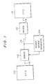
- Modems (modulator/demodulator) 10 are attached to respective DTEs 12 in the data communication system schematically shown in Fig. 5, and are connected with each other by a telephone circuit 14.
- the modem 10 is a device for modulating the signal from the DTE 12 to a signal suitable for the telephone circuit 14 and demodulating the signal received from the telephone circuit 14 to a signal suitable for the DTE 12, and plays an important role in a data communication system having the structure such as that shown in Fig. 5.
- the reference numeral 16 represents an RS232C cable.
- the modem 10 mainly includes a modulation and demodulation circuit 18 for modulating a digital signal supplied from the DTE 12 to a circuit signal, demodulating the received circuit signal to a digital signal of an RS232C type and supplying it to the DTE 12, and a net control unit 20 (hereinunder referred to as NCU) for controlling the connection between the modulation and demodulation circuit 18 and a telephone circuit 14.
- a modulation and demodulation circuit 18 for modulating a digital signal supplied from the DTE 12 to a circuit signal, demodulating the received circuit signal to a digital signal of an RS232C type and supplying it to the DTE 12, and a net control unit 20 (hereinunder referred to as NCU) for controlling the connection between the modulation and demodulation circuit 18 and a telephone circuit 14.
- NCU net control unit 20
- the modem 10 is further provided with a two-wire four-wire circuit 22, namely, a circuit for dividing the telephone circuit 14 connected to the terminals 11 and 12 of the NCU 20 into a transmitting circuit and a receiving circuit.
- a conventional data circuit-terminating equipment such as a modem has the above-described structure. This equipment is disadvantageous in that since a power source 24 exclusively for driving the equipment is necessary, the miniaturization of a data communication system is difficult.
- an equipment is provided with a power source device for extracting the power from the offhook current supplied from a telephone circuit and supplying the power from the power source device to a data circuit-terminating equipment such as a modem.
- the power source device can obtain a power for driving a modem or the like by utilizing the power of an offhook current which is conventionally wasted by an NCU or the like, it is possible to reduce the size of the equipment and improve the efficiency thereof.
- the power converter circuit includes, for example, a DC-DC converter.
- a DC-DC converter As the DC-DC converter, either a self-excited converter or a separately-excited converter may be used.
- the power source device may also include a battery which outputs a power only at the time of onhook.
- the modem In the case of using a modem as the data circuit-terminating equipment, the modem generally includes a modulation and demodulation circuit, a two-wire four-wire circuit and an NCU.
- the two-wire four-wire circuit receives and supplies a signal from and to the modulation and demodulation circuit by using a light receiving element and a light emitting element such as a photodiode. It is also preferable to provide the NCU with a light receiving element for detecting offhook.
- the NCU preferably includes a constant-current circuit, a shunt regulator, a smoothing circuit, etc.
- the DC-DC converter preferably supplies a power to both of the modulation and demodulation circuit and the two-wire four-wire circuit.
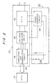
- the power source device 124 is connected to a telephone circuit 114 to take in the power of the circuit, thereby stabilizing the voltage, and outputs a predetermined voltage which is electrically separated from that of the input side so as to supply a power to, for example, the modem 110.
- the modem 110 is connected to a DTE 112 through an RS232C cable 116 and is also connected to the telephone circuit 114 through the modem 110.
- the modem 110 is connected to the telephone circuit 114 (not shown) through the terminals 11 and 12.
- a power converter circuit 126 including a DC-DC converter for converting the power of an offhook current is connected.
- An offhook current input from the terminals 11 and 12 is input to the power converter circuit 126 through an NCU 120.
- the NCU 120 supplies a signal current overlapping with the offhook current input from the terminals 11 and 12 to a two-wire four-wire circuit 122 and also supplies the residual current of the offhook current to the power converter circuit 126.
- the power converter circuit 126 converts the offhook current to a predetermined voltage level and supplies the thus-converted power to the two-wire four-wire circuit 122 and the modulation and demodulation circuit 118 as a driving power.
- a battery 128 supplies a power to the modulation and demodulation circuit 118 only when the circuit 114 is in the onhook state.
- a photocoupler PH1 in the NCU 120 is turned on, and transistors Tr1 and Tr2 are turned on, whereby a constant current flows from the telephone circuit 114.
- the current output from the telephone circuit 114 at this time is the offhook current and the offhook current is output to the two-wire four-wire circuit 122.
- the offhook current is further converted to four-wire signals by operational amplifiers I c1-1 and I c1-2 . Since the operational amplifiers I c1-1 and I c1-2 are connected to the modulation and demodulation circuit 118 (not shown) through the photocouplers PH2 and PH3, respectively, in the state of being insulated therefrom, the signals are transmitted and received between the operational amplifiers I c1-1 and I c1-2 and the modulation and demodulation circuit 118 (not shown).
- the NCU 120 is provided with a constant-current circuit 130, a shunt regulator 132 and a smoothing circuit 134.
- the constant-current circuit 130 is composed of a transistor Tr3, a resistance R3 and a capacitor C1. In the offhook state, since the impedance on the collector side of the transistor Tr3 becomes high, it is possible to transmit and receive a signal to the modulation and demodulation circuit 118 (not shown) through the two-wire four-wire circuit 122 which is connected to the collector side in the same way as in the prior art.
- the shunt regulator 132 which is composed of a Zener diode ZD1 and resistances R4 and R5, is provided in order to normally operate the power converter circuit 126 when the offhook current is slightly excessive.
- the smoothing circuit 134 is a circuit for smoothing the input current of the power converter circuit 126 and is composed of a coil L1 and a capacitor C2.
- the NCU 120 in this embodiment of an equipment of the present invention in the offhook state supplies a signal current input from the telephone circuit 114 to the two-wire four-wire circuit 122 and also supplies the residual current of the offhook current to the power converter circuit 126.
- the power converter circuit 126 is composed of what is called a self-excited converter. As the output terminals of the power converter circuit 126, a GND terminal, a positive terminal V cc1 and a negative terminal VEE1 for the two-wire four-wire circuit 122, and a terminal V cc2 for the modulation and demodulation circuit 118 are provided. Signals having the same voltage level when the GND is a zero point are output to the positive terminal V cc1 and the negative terminal VEE1 for the two-wire four-wire circuit 122.
- the positive terminal of the smoothing circuit 134 is connected through a resistor R6, and the emitter terminal of the transistor Tr4 is connected to the GND terminal.
- the collector terminal of the transistor Tr4 is connected to the positive terminal of the smoothing circuit 134 through a coiled winding n2 of a transformer T1.
- the transformer T1 further has a primary winding n1, which is wound so as to have the same polarity as the primary winding n2 and to be in series therewith.
- One end of the primary winding n1 is connected to the cathode of a diode D2 and the anode of the diode D2 is connected to the GND terminal.
- the other end of the primary winding n1 is connected to the base terminal of the transistor Tr4 through a capacitor C3.
- the primary circuit of the transformer T1 constitutes the self-excited oscillator, as described above. The oscillating operation will now be explained briefly.
- a charging current is supplied from the positive terminal of the smoothing circuit 134 to the capacitor C3 through the primary winding n1.
- the charging current acts in the direction of increasing the conductivity of the transistor Tr4, and the transistor Tr4 increases the collector current.
- the self-excited oscillation frequency is determined by the circuit constant and the load.
- a predetermined voltage level is output to the terminal V CC2 and supply of a power to the modulation and demodulation circuit 118 is also enabled.
- the shunt regulator 132 can be dispensed with, and the smoothing circuit 134 may use a transformer.
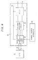
- Fig. 4 shows the structure of a second embodiment of an equipment according to the present invention, in particular, the structure of a power converter circuit 226.
- the power converter circuit 226 shown in Fig. 4 is a separately-excited DC-DC converter including a self-excited oscillator 228.
- the operation of the power converter circuit 226 is as follows.
- a transistor Tr14 is first switched by a synchronous signal output from the self-excited oscillator 228. When the transistor Tr14 is on, a current is supplied from the smoothing circuit 134 to the collector of the transistor Tr14 through a primary winding n12 of a transformer T11.
- a voltage is induced on a secondary winding n13, and the voltage is rectified by a diode D13 to be output to the outside, e.g., a two-wire four wire circuit and a modulation demodulation circuit (not shown).
- the winding of the transformer T11 is a forward type coil directed toward the converter, but it may be a flyback type coil.
- the offhook current input from the telephone circuit through the NCU is supplied to the data circuit-terminating equipment after the power of the current is converted, no device for self power supply is necessary, thereby enabling the realization a small-sized data communication system.
- a data circuit-terminating equipment with a power source device attached thereto comprising a data circuit-terminating equipment such as a modem and a power source device attached thereto for supplying a power extracted from a telephone circuit to the data circuit-terminating equipment.
Applications Claiming Priority (2)
| Application Number | Priority Date | Filing Date | Title |
|---|---|---|---|
| JP144263/88U | 1988-11-04 | ||
| JP1988144263U JPH0264261U (de) | 1988-11-04 | 1988-11-04 |
Publications (3)
| Publication Number | Publication Date |
|---|---|
| EP0367270A2 true EP0367270A2 (de) | 1990-05-09 |
| EP0367270A3 EP0367270A3 (de) | 1991-10-09 |
| EP0367270B1 EP0367270B1 (de) | 1996-02-07 |
Family
ID=15358029
Family Applications (1)
| Application Number | Title | Priority Date | Filing Date |
|---|---|---|---|
| EP89120311A Expired - Lifetime EP0367270B1 (de) | 1988-11-04 | 1989-11-02 | Datenübertragungseinrichtung mit zugeordneter Energieversorgungseinrichtung |
Country Status (6)
| Country | Link |
|---|---|
| US (1) | US5181240A (de) |
| EP (1) | EP0367270B1 (de) |
| JP (1) | JPH0264261U (de) |
| KR (1) | KR960009904B1 (de) |
| CA (1) | CA2001472C (de) |
| DE (1) | DE68925613T2 (de) |
Cited By (13)
| Publication number | Priority date | Publication date | Assignee | Title |
|---|---|---|---|---|
| FR2664776A1 (fr) * | 1990-07-10 | 1992-01-17 | Digitelec Inf Sarl | Modulateur - demodulateur alimente par la ligne telephonique. |
| EP0511514A2 (de) * | 1991-04-29 | 1992-11-04 | Siemens Aktiengesellschaft | Shaltungsanordnung zur Datenumsetzung |
| FR2705182A1 (fr) * | 1993-05-11 | 1994-11-18 | Etudes Realis Protect Electron | Agencement de liaison téléphonique notamment pour la télécommande d'un terminal d'abonné via le réseau téléphonique. |
| FR2705156A1 (fr) * | 1993-05-11 | 1994-11-18 | Etudes Realis Protect Electron | Agencement d'acquisition de données ou de transition de télécommande par le réseau téléphonique. |
| FR2799096A1 (fr) * | 1999-09-23 | 2001-03-30 | Grizzli Systems | Convertisseur de protocle pour services a l'habitat auto alimente |
| EP1093276A2 (de) * | 1999-10-08 | 2001-04-18 | Lucent Technologies Inc. | Verfahren zum Anfahren für ein internationales leitungsgespeistes DAA |
| EP1093277A2 (de) * | 1999-10-08 | 2001-04-18 | Lucent Technologies Inc. | Aufrechterhaltung einer Abhebungsbedingung für leitungsgespeiste DAA während eines Anrufes |
| EP1276305A1 (de) * | 2001-05-30 | 2003-01-15 | Texas Instruments Incorporated | System und Vorrichtung zur Isolation eines Modems |
| FR2859856A1 (fr) * | 2003-09-16 | 2005-03-18 | France Telecom | Systeme et disposiif d'alimentation a distance d'un equipement de traitement d'informations |
| WO2005101804A1 (en) * | 2004-04-13 | 2005-10-27 | Telecom Italia S.P.A. | A device and a method for feeding electric devices from a telephone line |
| US7986586B2 (en) | 2008-04-08 | 2011-07-26 | Pgs Geophysical As | Method for deghosting marine seismic streamer data with irregular receiver positions |
| US8274858B2 (en) | 2009-11-12 | 2012-09-25 | Pgs Geophysical As | Method for full-bandwidth deghosting of marine seismic streamer data |
| USRE43760E1 (en) | 2001-05-09 | 2012-10-23 | Ulrich Abel | Adjusting connection bandwidth in a data network |
Families Citing this family (22)
| Publication number | Priority date | Publication date | Assignee | Title |
|---|---|---|---|---|
| US5655009A (en) * | 1992-03-19 | 1997-08-05 | Fujitsu Limited | Modem unit |
| US5461671A (en) * | 1992-06-05 | 1995-10-24 | Murata Mfg. Co., Ltd. | Telephone line power utility circuit |
| US5343514A (en) * | 1993-12-10 | 1994-08-30 | Snyder Gary K | Telephone line powered system |
| US6175556B1 (en) * | 1994-06-06 | 2001-01-16 | International Business Machines Corporation | Remote powered ethernet repeater |
| WO1999053627A1 (en) | 1998-04-10 | 1999-10-21 | Chrimar Systems, Inc. Doing Business As Cms Technologies | System for communicating with electronic equipment on a network |
| US6480510B1 (en) | 1998-07-28 | 2002-11-12 | Serconet Ltd. | Local area network of serial intelligent cells |
| US6697485B1 (en) | 1998-11-10 | 2004-02-24 | 3Com Corporation | Data signal attenuator and systems and methods for using same |
| US6377667B1 (en) | 1999-03-15 | 2002-04-23 | 3Com Corporation | Telephone line-assist powered apparatus with programmable hold current |
| US6567472B1 (en) | 1999-05-26 | 2003-05-20 | 3Com Corporation | System and method for terminating a line by reflecting a scaled impedance |
| US6338077B1 (en) | 1999-05-28 | 2002-01-08 | 3Com Corporation | Transfer function implementation using digital impedance synthesis |
| US6456665B1 (en) | 1999-05-28 | 2002-09-24 | 3Com Corporation | Partial modification of a nominal impedance using digital impedance synthesis |
| US6956826B1 (en) | 1999-07-07 | 2005-10-18 | Serconet Ltd. | Local area network for distributing data communication, sensing and control signals |
| US6690677B1 (en) | 1999-07-20 | 2004-02-10 | Serconet Ltd. | Network for telephony and data communication |
| US6571181B1 (en) | 1999-08-11 | 2003-05-27 | Broadcom Corporation | System and method for detecting a device requiring power |
| US6654461B1 (en) | 1999-09-14 | 2003-11-25 | 3Com Corporation | Synthesized telephone line ring signal impedance termination |
| US6549616B1 (en) * | 2000-03-20 | 2003-04-15 | Serconet Ltd. | Telephone outlet for implementing a local area network over telephone lines and a local area network using such outlets |
| US6842459B1 (en) * | 2000-04-19 | 2005-01-11 | Serconet Ltd. | Network combining wired and non-wired segments |
| US7660408B1 (en) | 2000-04-28 | 2010-02-09 | 3Com Corporation | Attenuation and termination circuit using impedance synthesis |
| US6573729B1 (en) | 2000-08-28 | 2003-06-03 | 3Com Corporation | Systems and methods for impedance synthesis |
| IL154234A (en) | 2003-01-30 | 2010-12-30 | Mosaid Technologies Inc | Method and system for providing dc power on local telephone lines |
| IL159838A0 (en) | 2004-01-13 | 2004-06-20 | Yehuda Binder | Information device |
| EP2045791B1 (de) * | 2007-10-01 | 2014-01-15 | Siemens Aktiengesellschaft | Elektronische Vorrichtung |
Citations (6)
| Publication number | Priority date | Publication date | Assignee | Title |
|---|---|---|---|---|
| US4395590A (en) * | 1980-11-03 | 1983-07-26 | Universal Data Systems, Inc. | Line powered modem |
| JPS58159668A (ja) * | 1982-03-16 | 1983-09-22 | Canon Inc | 複写機の電源装置 |
| US4415774A (en) * | 1981-11-25 | 1983-11-15 | Universal Data Systems, Inc. | Line powered modem automatic answer device powered from equipment |
| JPS59188269A (ja) * | 1984-03-22 | 1984-10-25 | Anritsu Corp | 公衆電話機の制御回路用電源回路 |
| JPS60207454A (ja) * | 1984-03-30 | 1985-10-19 | Hitachi Ltd | スイツチングレギユレ−タ |
| US4593389A (en) * | 1984-06-28 | 1986-06-03 | Henry Wurzburg | Simultaneous voice and asynchronous data telephone |
Family Cites Families (4)
| Publication number | Priority date | Publication date | Assignee | Title |
|---|---|---|---|---|
| US4578533A (en) * | 1980-11-03 | 1986-03-25 | Universal Data Systems, Inc. | Switchable line powered modem |
| JPS6286947A (ja) * | 1985-10-12 | 1987-04-21 | Sharp Corp | デ−タ端末装置とデ−タ通信端末装置のインタ−フエイス |
| US4691344A (en) * | 1986-01-21 | 1987-09-01 | Aquatrol Corporation | Low-powered remote sensor and telephone line transmitter |
| US4803719A (en) * | 1987-06-04 | 1989-02-07 | Ulrich Thomas J | Method for powering telephone apparatus and telephone apparatus powered directly from the telephone line without external power |
-
1988
- 1988-11-04 JP JP1988144263U patent/JPH0264261U/ja active Pending
-
1989
- 1989-10-25 CA CA002001472A patent/CA2001472C/en not_active Expired - Fee Related
- 1989-11-02 EP EP89120311A patent/EP0367270B1/de not_active Expired - Lifetime
- 1989-11-02 KR KR1019890015848A patent/KR960009904B1/ko not_active IP Right Cessation
- 1989-11-02 DE DE68925613T patent/DE68925613T2/de not_active Expired - Fee Related
-
1991
- 1991-05-08 US US07/696,935 patent/US5181240A/en not_active Expired - Lifetime
Patent Citations (6)
| Publication number | Priority date | Publication date | Assignee | Title |
|---|---|---|---|---|
| US4395590A (en) * | 1980-11-03 | 1983-07-26 | Universal Data Systems, Inc. | Line powered modem |
| US4415774A (en) * | 1981-11-25 | 1983-11-15 | Universal Data Systems, Inc. | Line powered modem automatic answer device powered from equipment |
| JPS58159668A (ja) * | 1982-03-16 | 1983-09-22 | Canon Inc | 複写機の電源装置 |
| JPS59188269A (ja) * | 1984-03-22 | 1984-10-25 | Anritsu Corp | 公衆電話機の制御回路用電源回路 |
| JPS60207454A (ja) * | 1984-03-30 | 1985-10-19 | Hitachi Ltd | スイツチングレギユレ−タ |
| US4593389A (en) * | 1984-06-28 | 1986-06-03 | Henry Wurzburg | Simultaneous voice and asynchronous data telephone |
Non-Patent Citations (4)
| Title |
|---|
| IBM TECHNICAL DISCLOSURE BULLETIN, vol. 28, no. 2, July 1985, pages 668-669, New York, US; "Telephone line powered operation with FCC part 68 isolation" * |
| PATENT ABSTRACTS OF JAPAN, vol. 10, no. 54 (E-385)[2111], 4th March 1986; & JP-A-60 207 454 (HITACHI) 19-10-1985 * |
| PATENT ABSTRACTS OF JAPAN, vol. 7, no. 280 (E-216)[1425], 14th December 1983; & JP-A-58 159 668 (CANON) 22-09-1983 * |
| PATENT ABSTRACTS OF JAPAN, vol. 9, no. 47 (E-299)[1170], 27th February 1985; & JP-A-59 188 269 (ANRITSU) 25-10-1984 * |
Cited By (20)
| Publication number | Priority date | Publication date | Assignee | Title |
|---|---|---|---|---|
| FR2664776A1 (fr) * | 1990-07-10 | 1992-01-17 | Digitelec Inf Sarl | Modulateur - demodulateur alimente par la ligne telephonique. |
| EP0511514A2 (de) * | 1991-04-29 | 1992-11-04 | Siemens Aktiengesellschaft | Shaltungsanordnung zur Datenumsetzung |
| EP0511514A3 (en) * | 1991-04-29 | 1993-07-28 | Siemens Aktiengesellschaft | Data conversion circuit |
| US5392403A (en) * | 1991-04-29 | 1995-02-21 | Siemens Aktiengesellschaft | Circuit arrangement employing a microprocessor module for data conversion in a data transmission between a personal computer and communication equipment |
| FR2705182A1 (fr) * | 1993-05-11 | 1994-11-18 | Etudes Realis Protect Electron | Agencement de liaison téléphonique notamment pour la télécommande d'un terminal d'abonné via le réseau téléphonique. |
| FR2705156A1 (fr) * | 1993-05-11 | 1994-11-18 | Etudes Realis Protect Electron | Agencement d'acquisition de données ou de transition de télécommande par le réseau téléphonique. |
| FR2799096A1 (fr) * | 1999-09-23 | 2001-03-30 | Grizzli Systems | Convertisseur de protocle pour services a l'habitat auto alimente |
| EP1093277A3 (de) * | 1999-10-08 | 2003-11-12 | Lucent Technologies Inc. | Aufrechterhaltung einer Abhebungsbedingung für leitungsgespeiste DAA während eines Anrufes |
| EP1093277A2 (de) * | 1999-10-08 | 2001-04-18 | Lucent Technologies Inc. | Aufrechterhaltung einer Abhebungsbedingung für leitungsgespeiste DAA während eines Anrufes |
| EP1093276A2 (de) * | 1999-10-08 | 2001-04-18 | Lucent Technologies Inc. | Verfahren zum Anfahren für ein internationales leitungsgespeistes DAA |
| EP1093276A3 (de) * | 1999-10-08 | 2003-11-12 | Lucent Technologies Inc. | Verfahren zum anfahren für ein internationales leitungsgespeistes DAA |
| EP1890469A1 (de) * | 1999-10-08 | 2008-02-20 | Lucent Technologies Inc. | Verfahren zum Anfahren für ein internationales leitungsgespeistes DAA |
| USRE43760E1 (en) | 2001-05-09 | 2012-10-23 | Ulrich Abel | Adjusting connection bandwidth in a data network |
| EP1276305A1 (de) * | 2001-05-30 | 2003-01-15 | Texas Instruments Incorporated | System und Vorrichtung zur Isolation eines Modems |
| FR2859856A1 (fr) * | 2003-09-16 | 2005-03-18 | France Telecom | Systeme et disposiif d'alimentation a distance d'un equipement de traitement d'informations |
| WO2005029832A1 (fr) * | 2003-09-16 | 2005-03-31 | France Telecom | Systeme et dispositif d'alimentation a distance d'un equipement de traitement d'informations |
| WO2005101804A1 (en) * | 2004-04-13 | 2005-10-27 | Telecom Italia S.P.A. | A device and a method for feeding electric devices from a telephone line |
| US8050390B2 (en) | 2004-04-13 | 2011-11-01 | Telecom Italia S.P.A. | Device and a method for feeding electric devices from a telephone line |
| US7986586B2 (en) | 2008-04-08 | 2011-07-26 | Pgs Geophysical As | Method for deghosting marine seismic streamer data with irregular receiver positions |
| US8274858B2 (en) | 2009-11-12 | 2012-09-25 | Pgs Geophysical As | Method for full-bandwidth deghosting of marine seismic streamer data |
Also Published As
| Publication number | Publication date |
|---|---|
| DE68925613T2 (de) | 1996-07-25 |
| DE68925613D1 (de) | 1996-03-21 |
| EP0367270A3 (de) | 1991-10-09 |
| KR900008790A (ko) | 1990-06-03 |
| JPH0264261U (de) | 1990-05-15 |
| KR960009904B1 (ko) | 1996-07-24 |
| US5181240A (en) | 1993-01-19 |
| CA2001472C (en) | 1994-03-15 |
| EP0367270B1 (de) | 1996-02-07 |
| CA2001472A1 (en) | 1990-05-04 |
Similar Documents
| Publication | Publication Date | Title |
|---|---|---|
| EP0367270B1 (de) | Datenübertragungseinrichtung mit zugeordneter Energieversorgungseinrichtung | |
| US6489725B1 (en) | Power saving circuit | |
| US5040242A (en) | Optical communication apparatus and method | |
| GB1597606A (en) | Power supply apparatus | |
| US5602726A (en) | Uninterruptive switching regulator | |
| US4755922A (en) | DC to DC converter for ethernet transceiver | |
| EP0561644A2 (de) | Modemeinrichtung | |
| EP0087437B1 (de) | Schaltung für fernsprecherleitungen | |
| US4803722A (en) | Circuit for remote supply of subscriber line terminals in a telecommunication system | |
| CN211744117U (zh) | 一种兼容快速充电模式和普通充电模式的充电电路 | |
| KR100963024B1 (ko) | 플라이백 컨버터용 동기정류기 구동회로 | |
| JP3166898B2 (ja) | スイッチング電源 | |
| US5331213A (en) | Pulse transmission circuit with undershoot eliminating circuitry | |
| US4673884A (en) | Circuit for measuring the anode current in an X-ray tube | |
| JP2752053B2 (ja) | モデム装置 | |
| CA2000933C (en) | Data communications system | |
| JPH02113752A (ja) | 信号受信装置 | |
| CN112928786A (zh) | 一种无线充电装置与无线充电方法 | |
| CN211266542U (zh) | 一种可调节充电电流大小的快速充电系统 | |
| EP0651540B1 (de) | Fernsprech-Teilnehmerschaltung mit einem galvanischen Trennungselement | |
| JP3146631B2 (ja) | 電話回線電力利用回路 | |
| JPH06284714A (ja) | 絶縁型dc−dcコンバータ | |
| MXPA01011484A (es) | Sistema de suministro de energia basado en una linea telefonica. | |
| JPH08264207A (ja) | Acアダプタ兼充電装置 | |
| JPH03128671A (ja) | Dc―dcコンバータ回路 |
Legal Events
| Date | Code | Title | Description |
|---|---|---|---|
| PUAI | Public reference made under article 153(3) epc to a published international application that has entered the european phase |
Free format text: ORIGINAL CODE: 0009012 |
|
| AK | Designated contracting states |
Kind code of ref document: A2 Designated state(s): DE FR GB |
|
| PUAL | Search report despatched |
Free format text: ORIGINAL CODE: 0009013 |
|
| AK | Designated contracting states |
Kind code of ref document: A3 Designated state(s): DE FR GB |
|
| 17P | Request for examination filed |
Effective date: 19911017 |
|
| 17Q | First examination report despatched |
Effective date: 19930903 |
|
| GRAA | (expected) grant |
Free format text: ORIGINAL CODE: 0009210 |
|
| AK | Designated contracting states |
Kind code of ref document: B1 Designated state(s): DE FR GB |
|
| REF | Corresponds to: |
Ref document number: 68925613 Country of ref document: DE Date of ref document: 19960321 |
|
| ET | Fr: translation filed | ||
| PLBE | No opposition filed within time limit |
Free format text: ORIGINAL CODE: 0009261 |
|
| STAA | Information on the status of an ep patent application or granted ep patent |
Free format text: STATUS: NO OPPOSITION FILED WITHIN TIME LIMIT |
|
| 26N | No opposition filed | ||
| REG | Reference to a national code |
Ref country code: GB Ref legal event code: IF02 |
|
| PGFP | Annual fee paid to national office [announced via postgrant information from national office to epo] |
Ref country code: GB Payment date: 20051102 Year of fee payment: 17 |
|
| PGFP | Annual fee paid to national office [announced via postgrant information from national office to epo] |
Ref country code: FR Payment date: 20051108 Year of fee payment: 17 |
|
| PGFP | Annual fee paid to national office [announced via postgrant information from national office to epo] |
Ref country code: DE Payment date: 20061026 Year of fee payment: 18 |
|
| GBPC | Gb: european patent ceased through non-payment of renewal fee |
Effective date: 20061102 |
|
| REG | Reference to a national code |
Ref country code: FR Ref legal event code: ST Effective date: 20070731 |
|
| PG25 | Lapsed in a contracting state [announced via postgrant information from national office to epo] |
Ref country code: GB Free format text: LAPSE BECAUSE OF NON-PAYMENT OF DUE FEES Effective date: 20061102 |
|
| PG25 | Lapsed in a contracting state [announced via postgrant information from national office to epo] |
Ref country code: FR Free format text: LAPSE BECAUSE OF NON-PAYMENT OF DUE FEES Effective date: 20061130 |
|
| PG25 | Lapsed in a contracting state [announced via postgrant information from national office to epo] |
Ref country code: DE Free format text: LAPSE BECAUSE OF NON-PAYMENT OF DUE FEES Effective date: 20080603 |