EP0366926A2 - Arrangement de poteau pour clôtures - Google Patents
Arrangement de poteau pour clôtures Download PDFInfo
- Publication number
- EP0366926A2 EP0366926A2 EP89117672A EP89117672A EP0366926A2 EP 0366926 A2 EP0366926 A2 EP 0366926A2 EP 89117672 A EP89117672 A EP 89117672A EP 89117672 A EP89117672 A EP 89117672A EP 0366926 A2 EP0366926 A2 EP 0366926A2
- Authority
- EP
- European Patent Office
- Prior art keywords
- boom
- head
- bending beam
- sensor element
- cantilever
- Prior art date
- Legal status (The legal status is an assumption and is not a legal conclusion. Google has not performed a legal analysis and makes no representation as to the accuracy of the status listed.)
- Granted
Links
Images


Classifications
-
- G—PHYSICS
- G08—SIGNALLING
- G08B—SIGNALLING OR CALLING SYSTEMS; ORDER TELEGRAPHS; ALARM SYSTEMS
- G08B13/00—Burglar, theft or intruder alarms
- G08B13/02—Mechanical actuation
- G08B13/12—Mechanical actuation by the breaking or disturbance of stretched cords or wires
- G08B13/122—Mechanical actuation by the breaking or disturbance of stretched cords or wires for a perimeter fence
Definitions
- the invention relates to a boom device according to the preamble of claim 1.
- the known boom device from which the invention is based (brochure RKS "security fence - electronically monitored”) is particularly intended and suitable for securing high-security areas, weapon depots, machine parks or the like and is intended to prevent a corresponding enclosure from being climbed over. For example, it should be prevented that a top layer made of barbed wire can be overcome after being covered by blankets or the like.
- the jib head of the known jib device is monitored for pressure stress, so that it is ensured that a pushing of the jib head caused by the weight of an intruder into the jib carrier causes a signal of the evaluation and switching device.
- the printing device does not necessarily have to act directly between the boom head and the boom support, but rather the boom head can also have an elongated head holder which is displaceably guided in the boom carrier or in the boom head and the printing device is then arranged between the boom carrier and the boom head.
- the known boom device also has an effective upper holding device between the boom head and the boom carrier, by which the upper normal position of the boom head is defined and by which the boom head is pulled out of the boom carrier or prevented from being lifted upwards.
- the boom device is adjustable in terms of the weight that leads to an alarm being triggered by the fact that the vertical position of the upper holding device is adjustable.
- the consequence of this construction is that an individual adjustment on each fence post or the like is necessary and that when the adjustment is made to a different weight, the upper normal position of the boom head also changes at the same time. It has also been shown that a such cantilever head can be easily supported by mechanical means, in such a way that, despite weight loading, a longitudinal displacement of the cantilever head relative to the cantilever beam does not occur;
- the sensor element of the evaluation and switching device present in the known boom device is an electromechanical switch which can be actuated by the downward movement of the boom head or the head holder.
- the subject of a post-published prior art (EP-A 298 320, EP application 88 110 094.5) is a cantilever device of the type in question, in which the sensor element is flat and in a space between the end face of the cantilever beam facing the cantilever head and the End face of the boom carrier facing the boom head is arranged and responds to any change in position, in particular to an inclination of the boom head relative to the boom carrier.
- the sensor element here is a rubber buffer with several embedded sensors, which is biased by the upper holding device. This sensor element is arranged in the free space so that it is protected against external interference.
- the sensors are strain gauges, piezo elements or the like.
- the invention is based on the object of designing and developing the boom device described at the outset, which is known from the pre-published prior art, in such a way that high reliability and simplest setting options are linked to the lowest possible error alarm probability.
- Fig. 1 shows a perspective view of a section of a fence 1 in the form of a fence with fence mats 2, which are attached to fence posts 3, namely welded.
- the fence post 3 carries a cantilever head 4, which is designed as a Y-boom in the preferred exemplary embodiment shown here, and also provides only as a preferred one Use case, a receiving body for a cantilever beam 5 carrying the boom head 4.
- a receiving body for a cantilever beam 5 carrying the boom head 4.
- a variety of other alternatives are possible in principle, for example the use of a wall post as a receiving body, etc.
- a fence 1 in the form of a fence, ie with Fence post 3 and fence mats 2 ran out.
- Fig. 2 makes it clear that the boom head 4 does not necessarily have to have the shape of the Y-boom shown, but that the boom head 4 can also itself be a further fence post, the fence mat 2 attached to the boom head 4 can also be in one plane the fence mat 2 can lie on the fence post 3. It is also entirely possible that the boom support 5 is completely sunk into the ground, so that only the fence mat 2 attached to the boom head 4 appears as the actual fence.
- the evaluation and switching device 7 has a sensor element 8.
- the sensor element 8 determines a load or relief of the cantilever head 4 and when a limit value for the measurement signal of the sensor element 8 that can be set in the evaluation and switching device 7 is exceeded, a switching signal can be triggered by the evaluation and switching device 7.
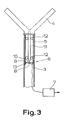
- the printing device 6 has a bending beam 9 arranged between an end face of the boom head 4 facing the boom support 5 and an end face of the boom support 5 facing the boom head 4 and that the end face of the boom head 4 rests on the freely floating bending area 10 of the bending beam 9 and that this Sensor element 8 is designed as an element which responds to the bending of the bending beam 9, in particular as a strain gauge sensor or the like, and is connected to the bending beam 9 or integrated in the bending beam 9. Even a slight displacement of the cantilever head 4, which only serves to transmit the necessary force to the bending beam 9, is sufficient in this construction to change the measurement signal of the sensor element 8.
- the sensor element has been moved into the interior of the fence post 3 or the like in order not to make it accessible from the outside.
- the boom device according to the invention which is therefore expediently characterized in that the boom head 4 has an elongated head holder 11 which extends deep into the boom carrier 5 and is guided in the boom carrier 5, and the bending beam 9 is deeply recessed in the boom carrier 5 at the lower end of the Head holder 11 is arranged.
- an elongated guide by means of a corresponding head holder 11 is recommended.
- the head holder 11 is guided in the cantilever support 5 in the illustrated, schematically represented exemplary embodiment by two bearings 12 at the upper end of the cantilever support 5 or at the lower end of the head holder 11, which are designed here as roller bearings or ball bearings, so that each one however Directional loading and unloading of the boom head 4 is transmitted to the bending beam 9 only in the form of a vertical force component.
- the bending beam 9 could in principle be clamped on one side, that is to say it could be designed as a cantilever. A two-sided clamping of the bending beam 9 would also be conceivable.
- the bending beam 9 is designed to rest on two sides, that is to say the end face of the cantilever beam 5 consists of two beam supports 13.
- the boom support 5 is designed as a sleeve inserted into the fence post 3 and at the end carrying the beam supports 13 in a flange-like manner. This is very useful in terms of construction, although other forms of construction are also conceivable.
- An alternative embodiment for bending beams and beam supports is not shown in the drawing. It is characterized in that the end face of the cantilever beam is designed as a ring, in particular as a circular ring, and the bending beam is designed as a correspondingly shaped disk resting on the ring or circular ring.
- a bending beam that rests on all sides, in the form of a bending disk, can be advantageous under certain conditions, for example when the bending beam itself is designed as a piezo element. This will be discussed in more detail later.
- the rest of the above-mentioned holding device should expediently be provided with travel limit stops for lifting the boom head from the boom carrier and / or pushing the boom head against the boom carrier. This prevents the bending beam from being overstressed and prevents damage or destruction of the sensor element 8 and the evaluation and switching device 7.
- strain gauges are preferably used for the sensor element 8.
- piezo elements are also conceivable as force transducers, for example also modern synthetic polymers which exhibit piezoelectric effects (e.g. polyvinylidene fluoride, PVF2).
- the sensor element For the purpose of increased measuring accuracy, it is recommended that the sensor element have a number of strain gauges or the like distributed on or in the bending beam.
- a differential measurement with several strain gauges or the like can be realized, for example, in that the sensor element has a strain gauge or the like both on the side of the bending beam facing the boom head and on the side of the bending beam facing away from the boom head, and the like the measurement signals from both strain gauges or the like can be combined in the evaluation and switching device for signal amplification.
- a sensor element 8 designed as a strain gauge sensor there are various possibilities for attaching the strain gauge (s) to or in the bending beam 9.
- a constructive solution has proven to be particularly expedient, which is characterized in that the sensor element 8 designed as a strain gauge sensor has, as a strain gauge, a resistance paste applied to an elastically deformable substrate, in particular an epoxy resin board.
- This solution is particularly useful because an electronic evaluation circuit of the evaluation and switching device 7 can be arranged or applied to such a substrate. A highly integrated circuit solution is thus achieved.
- the bending beam could itself form an overall sensor element.
- FIG. 4 shows a further exemplary embodiment of a cantilever device according to the invention, in which the sensor element 8 works capacitively.
- the bending beam 9 is at the same time a capacitor plate 13 of a measuring capacitor serving as a sensor element 8, which also has a fixed capacitor plate 14 attached to the cantilever support 5.
- a compressible or displaceable dielectric 15 is located between the capacitor plates 13, 14.
- the capacitance of the network capacitor serving as sensor element 8 is evaluated by means of the evaluation and switching device 7 indicated here.
- the bending beam 9 serving as the capacitor plate 13 is loaded, this capacitor plate 13 is in any case pressed closer to the capacitor plate 14 in the central region, so that the capacitance of the measuring capacitor increases.
- the capacitance is namely inversely proportional to the distance between the capacitor plates 13, 14.
- a correspondingly selected dielectric 15 with a high dielectric constant allows even high and strongly changing capacitance values to be achieved.
- the evaluation and switching device 7 can work with this capacitive measuring method, for example, so that the measuring capacitor is the frequency-determining variable of a response oscillator, so that a frequency change can be evaluated, or that there is a corresponding change in the amplitude of the oscillator oscillation, which can also be evaluated.
- the capacitor plate 13 can of course also be attached to the bending beam 9, the only essential factor is the change in the distance of the capacitor plates 13, 14 depending on the load condition of the boom head 4.
- the following also applies that at the lower end of the boom carrier 5 a trough-like receiving cap 16 for the capacitor plates 13, 14 is attached via fastening screws 17.
- a further preferred embodiment applies, which is characterized in that in the evaluation and switching device, an independently acting compensation for slow changes in the measurement signal nals of the sensor element, that is, an automatic zero point correction is provided.
- an automatic zero point correction it can be achieved, for example, that a slowly increasing snow load on the boom head does not lead to an alarm.
- external limit values will probably also be provided for this zero point correction.
Landscapes
- Physics & Mathematics (AREA)
- General Physics & Mathematics (AREA)
- Measurement Of Length, Angles, Or The Like Using Electric Or Magnetic Means (AREA)
- Component Parts Of Construction Machinery (AREA)
Applications Claiming Priority (2)
| Application Number | Priority Date | Filing Date | Title |
|---|---|---|---|
| DE3837902 | 1988-11-04 | ||
| DE3837902A DE3837902C1 (fr) | 1988-11-04 | 1988-11-04 |
Publications (3)
| Publication Number | Publication Date |
|---|---|
| EP0366926A2 true EP0366926A2 (fr) | 1990-05-09 |
| EP0366926A3 EP0366926A3 (en) | 1990-10-10 |
| EP0366926B1 EP0366926B1 (fr) | 1993-12-29 |
Family
ID=6366744
Family Applications (1)
| Application Number | Title | Priority Date | Filing Date |
|---|---|---|---|
| EP89117672A Expired - Lifetime EP0366926B1 (fr) | 1988-11-04 | 1989-09-25 | Arrangement de poteau pour clôtures |
Country Status (2)
| Country | Link |
|---|---|
| EP (1) | EP0366926B1 (fr) |
| DE (2) | DE3837902C1 (fr) |
Families Citing this family (4)
| Publication number | Priority date | Publication date | Assignee | Title |
|---|---|---|---|---|
| US10858857B2 (en) * | 2015-07-01 | 2020-12-08 | Stefan Doelling | Anti-climbing device |
| CN113006450A (zh) * | 2021-02-10 | 2021-06-22 | 上海建工集团股份有限公司 | 一种导架爬升式工作平台系统穿越障碍物的方法 |
| CN112982937A (zh) * | 2021-02-10 | 2021-06-18 | 上海建工集团股份有限公司 | 一种实现障碍物避让的导架爬升式工作平台系统 |
| WO2022264140A1 (fr) * | 2021-06-15 | 2022-12-22 | D-Fence Electronic Fencing And Security Systems Ltd. | Support supérieur de clôture pour détection d'intrusion |
Citations (3)
| Publication number | Priority date | Publication date | Assignee | Title |
|---|---|---|---|---|
| DE2717906A1 (de) * | 1977-04-22 | 1978-10-26 | Ernst Blaser | Bewegungsmelder fuer zaunanlagen |
| US4356423A (en) * | 1980-11-28 | 1982-10-26 | Teledyne Industries, Inc., Geotech Division | Pressure sensitive intrusion sensing line |
| US4367459A (en) * | 1980-06-05 | 1983-01-04 | Yoel Amir | Taut wire intrusion detection system and detectors useful therein |
Family Cites Families (1)
| Publication number | Priority date | Publication date | Assignee | Title |
|---|---|---|---|---|
| EP0298320A1 (fr) * | 1987-07-09 | 1989-01-11 | Wilhelm Rademacher | Dispositif support |
-
1988
- 1988-11-04 DE DE3837902A patent/DE3837902C1/de not_active Expired - Lifetime
-
1989
- 1989-09-25 EP EP89117672A patent/EP0366926B1/fr not_active Expired - Lifetime
- 1989-09-25 DE DE89117672T patent/DE58906568D1/de not_active Expired - Lifetime
Patent Citations (3)
| Publication number | Priority date | Publication date | Assignee | Title |
|---|---|---|---|---|
| DE2717906A1 (de) * | 1977-04-22 | 1978-10-26 | Ernst Blaser | Bewegungsmelder fuer zaunanlagen |
| US4367459A (en) * | 1980-06-05 | 1983-01-04 | Yoel Amir | Taut wire intrusion detection system and detectors useful therein |
| US4356423A (en) * | 1980-11-28 | 1982-10-26 | Teledyne Industries, Inc., Geotech Division | Pressure sensitive intrusion sensing line |
Also Published As
| Publication number | Publication date |
|---|---|
| EP0366926B1 (fr) | 1993-12-29 |
| DE3837902C1 (fr) | 1990-03-29 |
| DE58906568D1 (de) | 1994-02-10 |
| EP0366926A3 (en) | 1990-10-10 |
Similar Documents
| Publication | Publication Date | Title |
|---|---|---|
| DE102007035348A1 (de) | Fallgewichtsprüfgerät zur Bestimmung der Verformungskennwerte unter definierten Stoßbelastungen von Böden | |
| EP0232514A2 (fr) | Capteur de force | |
| DE102005030971A1 (de) | Kugelgelenk mit Sensoreinrichtung, Verfahren zur Belastungsmessung und Verfahren zur Verschleißmessung | |
| EP0034656A1 (fr) | Plateforme de pesage et procédé pour la fabrication de telles plates-formes de pesage | |
| DE1931308C3 (de) | Elektrische Vorrichtung zum Schutz beweglicher Gegenstände | |
| DE4012902C1 (fr) | ||
| EP0366926B1 (fr) | Arrangement de poteau pour clôtures | |
| EP1785704A1 (fr) | Module de pesage | |
| WO1989003503A1 (fr) | Goniometre avec capteur electronique de mesure et affichage numerique | |
| DE10132269A1 (de) | Drucksensor | |
| DE10359460B4 (de) | Wägezelle | |
| CH652209A5 (de) | Kraftmesser. | |
| DE2849641A1 (de) | Waage | |
| EP1001247A2 (fr) | Indicateur de position pour mesurer le chemin de mise en prise d'élévation du rouleau d'une charpente de laminoir | |
| DE4211507C1 (en) | Vehicle inclination monitoring circuit for antitheft appts. - has semiconductor sensor whose resistance varies w.r.t. deflection caused by movement of mass in centre of beam | |
| DE19858828A1 (de) | Kapazitiver Sensor | |
| DE19910003A1 (de) | Überlastsicherung für Aufnehmer mit Dehnungsmeßstreifen | |
| DE19838371C2 (de) | Waage | |
| DE19910692C2 (de) | Elektronisches Gerät | |
| DE19701462C2 (de) | Meßvorrichtung | |
| DE102018129542B4 (de) | Maschinenaufstelleinheit | |
| EP0726449B1 (fr) | Dispositif de mesure portatif pour déterminer le poids d'un véhicule | |
| EP0175917A2 (fr) | Dispositif de mesure de force | |
| EP0298320A1 (fr) | Dispositif support | |
| EP0331769A1 (fr) | Dispositif de mesure de la répartition bidimensionnelle de la pression |
Legal Events
| Date | Code | Title | Description |
|---|---|---|---|
| PUAI | Public reference made under article 153(3) epc to a published international application that has entered the european phase |
Free format text: ORIGINAL CODE: 0009012 |
|
| 17P | Request for examination filed |
Effective date: 19891228 |
|
| AK | Designated contracting states |
Kind code of ref document: A2 Designated state(s): BE DE FR IT LU NL |
|
| PUAL | Search report despatched |
Free format text: ORIGINAL CODE: 0009013 |
|
| AK | Designated contracting states |
Kind code of ref document: A3 Designated state(s): BE DE FR IT LU NL |
|
| 17Q | First examination report despatched |
Effective date: 19930125 |
|
| GRAA | (expected) grant |
Free format text: ORIGINAL CODE: 0009210 |
|
| AK | Designated contracting states |
Kind code of ref document: B1 Designated state(s): BE DE FR IT LU NL |
|
| PG25 | Lapsed in a contracting state [announced via postgrant information from national office to epo] |
Ref country code: IT Free format text: LAPSE BECAUSE OF FAILURE TO SUBMIT A TRANSLATION OF THE DESCRIPTION OR TO PAY THE FEE WITHIN THE PRESCRIBED TIME-LIMIT;WARNING: LAPSES OF ITALIAN PATENTS WITH EFFECTIVE DATE BEFORE 2007 MAY HAVE OCCURRED AT ANY TIME BEFORE 2007. THE CORRECT EFFECTIVE DATE MAY BE DIFFERENT FROM THE ONE RECORDED. Effective date: 19931229 Ref country code: FR Effective date: 19931229 Ref country code: NL Effective date: 19931229 Ref country code: BE Effective date: 19931229 |
|
| REF | Corresponds to: |
Ref document number: 58906568 Country of ref document: DE Date of ref document: 19940210 |
|
| EN | Fr: translation not filed | ||
| NLV1 | Nl: lapsed or annulled due to failure to fulfill the requirements of art. 29p and 29m of the patents act | ||
| PG25 | Lapsed in a contracting state [announced via postgrant information from national office to epo] |
Ref country code: LU Free format text: LAPSE BECAUSE OF NON-PAYMENT OF DUE FEES Effective date: 19940930 |
|
| PLBE | No opposition filed within time limit |
Free format text: ORIGINAL CODE: 0009261 |
|
| STAA | Information on the status of an ep patent application or granted ep patent |
Free format text: STATUS: NO OPPOSITION FILED WITHIN TIME LIMIT |
|
| 26N | No opposition filed | ||
| PGFP | Annual fee paid to national office [announced via postgrant information from national office to epo] |
Ref country code: DE Payment date: 20080930 Year of fee payment: 20 |