EP0366863A2 - An oxygen sensor device - Google Patents
An oxygen sensor device Download PDFInfo
- Publication number
- EP0366863A2 EP0366863A2 EP89111786A EP89111786A EP0366863A2 EP 0366863 A2 EP0366863 A2 EP 0366863A2 EP 89111786 A EP89111786 A EP 89111786A EP 89111786 A EP89111786 A EP 89111786A EP 0366863 A2 EP0366863 A2 EP 0366863A2
- Authority
- EP
- European Patent Office
- Prior art keywords
- solid electrolyte
- sensor device
- oxygen sensor
- electrolyte plate
- glass
- Prior art date
- Legal status (The legal status is an assumption and is not a legal conclusion. Google has not performed a legal analysis and makes no representation as to the accuracy of the status listed.)
- Granted
Links
Images


Classifications
-
- G—PHYSICS
- G01—MEASURING; TESTING
- G01N—INVESTIGATING OR ANALYSING MATERIALS BY DETERMINING THEIR CHEMICAL OR PHYSICAL PROPERTIES
- G01N27/00—Investigating or analysing materials by the use of electric, electrochemical, or magnetic means
- G01N27/26—Investigating or analysing materials by the use of electric, electrochemical, or magnetic means by investigating electrochemical variables; by using electrolysis or electrophoresis
- G01N27/403—Cells and electrode assemblies
- G01N27/406—Cells and probes with solid electrolytes
- G01N27/407—Cells and probes with solid electrolytes for investigating or analysing gases
- G01N27/4071—Cells and probes with solid electrolytes for investigating or analysing gases using sensor elements of laminated structure
Definitions
- the glass dome may be formed of a plurality of glass layers.
- the glass dome preferably has a double layer structure formed of a glass layer of high electrically insulating properties, such as one made of crystallized glass, and a glass layer of high sealing properties, such as one made of non-crystallized glass.
- the porous inorganic material packing layer mentioned before is formed of an antifire material which does not melt at the temperature used for forming the glass dome.
- antifire materials are ceramics (e.g., aluminum oxide, zirconia, calcium oxide, silicon carbide, silicone nitride, spinel, silica, magnesia, mullite) and metals (e.g., iron, nickel, chrome, manganese).
- the proportion of the volume of the void portion to the entire volume of the diffusion chamber is generally about 20 % or higher.
- the glass dome or the solid electrolyte plate has a gas inlet means for diffusing ambient gas into the diffusion chamber.
- the method for providing a gas inlet means is not critical.
- a gas inlet means may be provided by forming cracks in the glass dome as shown in Figs. 2, 3 and 4.
- glass dome 4 has fine cracks 5. Fine cracks 5 can be formed in glass dome 4 by applying heat shock thereto once or twice.
- a gas inlet means may be provided in the glass dome by planting in the glass-containing layer a fiber capable of melting or burning at the melting temperature of the powdery glass, followed by firing to obtain a glass dome having an orifice.
- the fiber may be made of aluminum, magnesium or the like. The fiber may simply be planted in the powdery glass-containing material so that it reaches the burnable material layer or the antifire material layer.
- the inner end portion of the fiber may optionally be coated with an organic material in the same manner as in the case of the capillary. When firing is performed, the fiber is melted or burnt to form an orifice, and the organic material is burnt off to leave a vacant portion around the inner end portion of the orifice. As described before, the vacant portion is effective for facilitating the diffusion of ambient gas into the diffusion chamber.
- One form of an oxygen sensor device of the present invention can be produced by method (I) comprising the steps of:
- a powdery zirconia containing 8 % by mole of a powdery Y2O3 is incorporated in a rubber tube.
- a yarn made of, for example, a polyester fiber, such as Tetron® or carbon fiber longitudinally extends under tension through the center line of the rubber tube.
- the powdery zirconia with the yarn passing therethrough is compressed under a pressure of, for example, about 1000 kg/cm2.
- the compressed zirconia is taken out of the rubber tube and fired at 1600 °C for 3 hours to obtain a rod-shaped fired zirconia product having an aperture passing therethrough.
- the prevention of electrical leak from the heater means contributes to not only high performance of the oxygen sensor device but also energy saving.
- solid electrolyte plate 1 is made of zirconium powder containing 8 mol % of Y2O3 and has a round shape of a size of 6 mm in diameter and 0.2 mm in thickness.
- Solid electrolyte plate 1 has, at its center portion, gas inlet means 7 in the form of a through-hole having a diameter of 10 ⁇ m.
- Two electrodes 2A and 2B are made of platinum and have a size of 4 mm in diameter and 5 ⁇ m in thickness.
- the oxygen sensor device of the present invention shows relatively prompt response to the change in the oxygen concentration of the ambient gas.
Abstract
Description
- The present invention relates to an oxygen sensor device. More particularly, the present invention is concerned with an oxygen sensor device having a glass dome fluid-tightly connected at its circumferential base edge to one surface of an oxygen conductive solid electrolyte plate to form a diffusion chamber defined by the glass dome and the solid electrolyte plate. The oxygen sensor device is advantageous from the viewpoints of miniaturization, power consumption saving and reliability. The advantageous oxygen sensor device can be efficiently produced by a novel method, in which a burnable material layer, a porous antifire material layer or a combination of a burnable material layer and a porous antifire material layer is formed on an oxygen conductive solid electrolyte plate and a powdery glass-containing pasty material is coated thereon, followed by firing. By virtue of the novel method, it is possible to perform continuous mass production of the oxygen sensor device at low cost, with the minimized occurrence of defectives.
- Oxygen determining devices are required when human beings must work in confined spaces, such as mines, tanks, etc. Oxygen determining devices are also requisite in extremely diversified fields, such as space ships and capsules, submarines for naval and civilian use, medical treatment, food pack inspection as well as combustion control and other environmental studies. Although several types of oxygen sensor devices have been proposed, there is still a strong demand for a small reliable oxygen sensor device.
- A representative form of the conventional oxygen sensor device is shown in Fig. 1. The device comprises
diffusion housing 104, oxygenconductive plate 101 of solid electrolyte hermetically bonded at its one surface todiffusion housing 104 bysealing glass 107, and a pair ofcircular electrode layers conductive plate 101, respectively. Electrodes 102A and 102B are connected to a DC power source. For example, the oxygenconductive plate 101 comprises a solid solution containing ZrO₂, Y₂O₃, MgO and CaO. Each ofelectrode layers Diffusion housing 104 has orifice 105 (gas inlet means) of a small diameter formed through the wall of the housing. The diffusion of oxygen from the monitored gas environment through gas inlet means 105 intochamber 103 ofdiffusion housing 104 is effected by the application of a DC potential from a power source across twoelectrodes chamber 103 through oxygenconductive plate 101. As the potential across twoelectrodes electrodes - In another conventional oxygen sensor device, the diffusion housing is made of an open-cell porous structure, with the gas inlet means omitted. With this construction, the oxygen diffuses into the chamber defined by the housing and the electrolyte plate through the pores of the housing.
- Generally, it is desired that the oxygen sensor device have a small size, because, with the small size, it is easy to heat up the device and perform temperature control at the time of oxygen determination, and the oxygen sensor device can be applied to oxygen determination even when the space at the oxygen determination site is limited. In manufacturing the above-mentioned conventional oxygen sensor devices, miniaturization of the device to a size of some millimeters is accompanied by difficulties in the fabrication and assembly of components, such as housing and solid electrolyte. For example,
diffusion housing 104 is made of a hard material, such as that prepared by firing a ceramic. It is very difficult to rework such a hard material into a diffusion housing of small size which has complicated configuration. Further, it is also very difficult to fluid-tightly connect such a small diffusion housing to a solid electrolyte plate. In particular, the connection of the diffusion housing to the solid electrolyte plate is carried out by applying sealing glass and then melting the glass in a high-temperature oven. However, this operation is likely to cause positional displacement, thereby leading to a high ratio of defectives. Because of the above-mentioned difficulties, the conventional oxygen sensor devices is likely to lack reliability in quality, and the productivity of the devices is disadvantageously low. - U.S. Patent No. 4,762,605 discloses an improved method for manufacturing an oxygen sensor device. In the improved method, a green sheet is used. The terminology "green sheet" used herein means a flexible plate or sheet comprising ceramic particles bound with a plasticizer, such as that prepared by first blending together a powdery ceramic, an organic resin plasticizer, e.g., polyethylene glycol, and a solvent, e.g., water and an alcohol, secondly extruding the resultant blend through roles or a slit into a sheet and thirdly evaporating the solvent at a temperature, e.g. 100 ° to 500 °C. A representative mode of this improved method is described below. First, a layer of a burnable resin material is disposed on the cathode side of an oxygen conductive solid electrolyte plate sandwiched between a porous cathode and a porous anode. Secondly, a pin-shaped protrusion made of the same resin material or of a hard plastic or an aluminum filament each having a low melting temperature is embedded in the layer of the burnable resin material. Thirdly, the above-mentioned green sheet is disposed on the layer of the burnable resin material. At this time, the protrusion passes through the layer. Finally, firing is performed. As a result, the plasticizer, the resin material and the hard plastic are burnt, and the aluminum filament is melted off. Thus, an oxygen sensor device comprising an oxygen conductive solid electrolyte plate sandwiched between a porous cathode and a porous anode and a ceramic diffusion housing connected at its circumferential base edge to the cathode side of the solid electrolyte plate, is obtained, having a similar structure to that of Fig. 1. In this method, the firing must be performed at a temperature as high as about 1600 °C. This high temperature firing is likely to damage the pore structure of the cathode and anode, because the pore structure of each electrode is adversely affected at a temperature of higher than 1000 °C. Also, the temperature as high as about 1600 °C is likely to cause deformation of the electrolyte plate. Therefore, it is very difficult to produce continuously such a type of oxygen sensor with uniform, excellent quality on a commercial scale.
- The present inventors have made extensive and intensive studies with a view toward obviating the drawbacks of the prior art. As a result, the inventors have unexpectedly found that an oxygen sensor device which is desirable from the viewpoints of miniaturization, power consumption saving and reliability can be realized by a structure in which a glass dome is fluid-tightly connected at its circumferential base edge to one surface of an oxygen conductive solid electrolyte plate. In view of the general knowledge with respect to the properties of glasses, it is surprising that an oxygen sensor device, the housing of which is constructed of a glass dome, can endure heat hysteresis caused by the change of temperature in the range of from room temperature (at the time the sensor is not working) to about 500 °C or higher (at the time the sensor is working). Moreover, the inventors have found that the desirable oxygen sensor device can be efficiently produced by first forming a burnable material layer, a porous antifire material layer or a composite layer of bunrnable material and porous antifire material on an electrode-carrying oxygen conductive solid electrolyte, and coating thereon, e.g., by screen printing, a powdery glass-containing pasty material, followed by firing at a relatively low temperature, e.g. 600° to 1000 °C. It is also surprising that the presence of the porous antifire material layer in the chamber defined by the glass dome and the solid electrolyte does not adversely affect the diffusion of gas and the sensitivity of the ultimate oxygen sensor device. Based on these novel findings, the present invention has been completed.
- Accordingly, it is an object of the present invention to provide a novel oxygen sensor device which is desirable from the viewpoints of miniaturization, power consumption saving and reliability.
- The foregoing and other objects, features and advantages of the present invention will be apparent from the following detailed description and appended claims taken in connection with the accompanying drawings.
- In the accompanying drawings:
- Fig. 1 is a diagrammatic cross-sectional view of a typical form of the conventional oxygen sensor device;
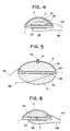
- Fig. 2 is a diagrammatic cross-sectional view of one form of the oxygen sensor device of the present invention, in which the diffusion chamber defined by a solid electrolyte plate and a glass dome formed thereon is vacant, the glass dome having cracks as a gas inlet means for diffusing ambient gas into the diffusion chamber;
- Fig. 3 is a diagrammatic cross-sectional view of another form of the oxygen sensor device of the present invention, which is similar to that of Fig. 1 but in which a porous inorganic material is fixedly disposed in the entire space of the diffusion chamber;
- Fig. 4 is a diagrammatic cross-sectional view of still another form of the oxygen sensor device of the present invention, which is similar to that of Fig. 3 but in which a porous inorganic material is fixedly disposed in only an upper portion of the diffusion chamber;
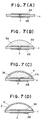
- Fig. 5 is a diagrammatic cross-sectional view of a further form of the oxygen sensor device of the present invention, in which the gas inlet means is a capillary planted in the glass dome formed on one side of the solid electrolyte plate and the inorganic material packing layer formed on the opposite side of the solid electrolyte plate has no glass dome thereon but has a heater means disposed directly thereon;
- Fig. 6 is a diagrammatic cross-sectional view of still a further form of the oxygen sensor device of the present invention, in which the gas inlet means is an aperture formed in the solid electrolyte plate;
- Fig. 7(A) to 7(D) are diagrammatic cross-sectional views to be used for explaining a method for producing an oxygen sensor device of the present invention in which the diffusion chamber is vacant;
- Figs. 7(A) to 7(C) are diagrammatic cross-sectional views to be used for explaining a method for producing an oxygen sensor device of the present invention in which a porous inorganic material is fixedly disposed in the diffusion chamber;
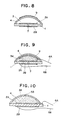
- Fig. 8 is a diagrammatic cross-sectional view of still a further form of the oxygen sensor device of the present invention, in which a heater means is disposed on the outer wall surface of the glass dome;
- Fig. 9 is a diagrammatic cross-sectional view of still a further form of the oxygen sensor device of the present invention, in which a heater means is disposed on the inner wall surface of the glass dome;
- Fig. 10 is a diagrammatic cross-sectional view of still a further form of the oxygen sensor device of the present invention, in which a portion of the first electrode protrudes outside the glass dome;
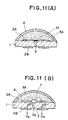
- Fig. 11(A) is a diagrammatic view explaining how to prevent the aperture of the solid electrolyte plate from clogging during the formation of a packing layer and a glass dome thereon;
- Figs. 11(B) is a diagrammatic cross-sectional view of the oxygen sensor device of the present invention produced by the method shown in Fig. 11(A);
- Figs. 12(A), 12(B) and 12(C) are, respectively, a diagrammatic cross-sectional side view, a diagrammatic plan view, and a diagrammatic bottom view of still a further form of the oxygen sensor device of the present invention, which further comprises a leg member attached at its one end portion to the outer surface of the glass dome through an adhesive layer and in which the gas inlet means is provided in the solid electrolyte plate;
- Fig. 13 is a diagrammatic cross-sectional side view similar to Fig. 16(B) but in which the leg member and adhesive layer have through-holes in registry with the aperture of the solid electrolyte plate;
- Fig. 14 is a diagrammatic perspective view explaining the conventional manner for disposing an oxygen sensor device in a casing;
- Fig. 15(A) is a diagrammatic cross-sectional side view of still a further form of the oxygen sensor device of the present invention, which is constructed into a unit in which the leg member is fixedly inserted in a slit of a support plate and fixed thereto, with a free end portion of the leg member being protruded through the slit for being easily connected to the connector means of power source means;
- Fig. 15(B) is a diagrammatic plan view of the support plate shown in Fig. 15(A); and
- Fig. 16 is a graph showing volt-ampere characteristics exhibited by an oxygen sensor device of the present invention.
- In Figs. 1 through 16, like parts or portions are designated by like numerals or characters.
- Essentially, according to the present invention, there is provided an oxygen sensor device comprising:
an oxygen conductive solid electrolyte plate;
a first electrode and a second electrode respectively disposed on the upper surface and the lower surface of said solid electrolyte plate;
a first electric lead means and a second electric lead means respectively for connecting said first and second electrodes to power source means; and
a glass dome fluid-tightly connected at its circumferential base edge to the upper surface of said solid electrolyte plate to provide at least one diffusion chamber defined by said glass dome and said solid electrolyte plate, said glass dome comprising at least one glass layer;
said glass dome or said solid electrolyte plate having a gas inlet means for diffusing ambient gas into said diffusion chamber;
said oxygen sensor device being operable by energizing said solid electrolyte plate, so that oxygen is pumped out of said diffusion chamber through said solid electrolyte plate to flow electric current across said first and second electrodes, said electric current being indicative of the partial pressure of the oxygen in the ambient gas. - The present invention will now be described in more detail with reference to the accompanying drawings.
- In the oxygen sensor device of the present invention, the diffusion chamber defined by the glass dome and the solid electrolyte plate having a pair of electrodes disposed on the upper surface and the lower surface thereof may be vacant, or may have a porous inorganic material packing layer fixedly disposed in the entire space thereof. Alternatively, the diffusion chamber may have a porous inorganic material semi-packing layer fixedly disposed in an upper portion thereof remote from the electrolyte plate, while leaving vacant the remainder of the chamber. The vacant diffusion chamber, the diffusion chamber having the packing layer and the diffusion chamber having the semi-packing layer are shown in Figs. 2 to 4, respectively.
- Referring now to Fig. 2, numeral 1 designates a solid electrolyte plate having oxygen ion conductivity upon energization of the electrolyte,
numerals glass dome 4 as a gas inlet means, andnumerals porous electrodes Glass dome 4 and electrode-carrying solid electrolyte plate 1 definevacant diffusion chamber 3. - In Fig. 3, porous inorganic
material packing layer 3A is fixedly disposed in the entire space of the diffusion chamber defined byglass dome 4 and solid electrolyte plate 1. - In Fig. 4, porous inorganic
material semi-packing layer 3B is fixedly disposed in an upper portion of the diffusion chamber defined byglass dome 4 and solid electrolyte plate 1, which upper portion is remote from solid electrolyte plate 1, while leaving vacant the remainder of the diffusion chamber to formvacant portion 3C. - In the oxygen sensor device of the present invention, there are no particular limitations with respect to the thickness of the glass dome, the thickness of the porous inorganic material packing or semi-packing layer and the thickness of the solid electrolyte plate. However, from a practical point of view, the thickness of the glass dome and the thickness of the porous inorganic material packing layer and the thickness of the solid electrolyte plate are generally in the ranges of from 5 to 30 µm, from 5 to 20 µm and from 0.1 to 1 mm, respectively. The thickness of the solid electrolyte plate is preferably in the range of from 0.1 to 0.4 mm. In the case of the oxygen sensor device having a porous inorganic material semi-packing layer, the thickness of the vacant portion of the diffusion chamber has no particular limitation, but is generally in the range of from 1 to 5 µm. When the gas inlet means is provided in the solid electrolyte plate, the diameter of the gas inlet means is generally in the range of from 10 to 100 µm. When the gas inlet means is provided in the glass dome, the diameter of the gas inlet means is preferably in the range of from 30 to 100 µm.
- With respect to the shape of the glass dome, there is also no limitation. Although the shape of semi-circle in cross-section is shown herein, any other shapes including rectangular shape can be used.
- The type of glass for forming the glass dome is not critical. Examples of glass compositions are shown in Table 1.
Table 1 Composition (% by weight) Thermal expansion coefficient 10⁻⁷/°C Type of Glass Na₂O K₂O BaO SiO₂ B₂O₃ Al₂O₃ MgO CaO ZnO PbO SnO₂ A 12 15 25 25 20 100 B 3 20 45 2 10 15 78 C 50 30 12 8 73 D 35 25 20 15 99 E 18 14 25 40 1.5 125 - When heated to certain temperatures, some types of glass are crystallized, while other types of glass are not crystallized and remain in an amorphous state. The glass to be used for forming the glass dome of the oxygen sensor device of the present invention can be selected from either of the above-mentioned two different types. Types A, D and E shown in Table 1 are crystallizable. On the other hand, types B and C are non-crystallizable.
- In the present invention, if desired, the glass dome may be formed of a plurality of glass layers. As described later, from the viewpoint of power consumption saving, the glass dome preferably has a double layer structure formed of a glass layer of high electrically insulating properties, such as one made of crystallized glass, and a glass layer of high sealing properties, such as one made of non-crystallized glass.
- The porous inorganic material packing layer mentioned before is formed of an antifire material which does not melt at the temperature used for forming the glass dome. Representative examples of antifire materials are ceramics (e.g., aluminum oxide, zirconia, calcium oxide, silicon carbide, silicone nitride, spinel, silica, magnesia, mullite) and metals (e.g., iron, nickel, chrome, manganese). The proportion of the volume of the void portion to the entire volume of the diffusion chamber is generally about 20 % or higher.
- In general, the volume of the diffusion chamber should be as small as possible. The ambient pressure often suffers from sharp increase due to the change of climate, occurrence of bursting of steam, operation of an air conditioner and the like. If the volume of the diffusion chamber is too large and the ambient pressure outside the diffusion chamber is sharply increased, a large amount of ambient gas flows into the diffusion chamber, resulting in a sharp increase in the electric current. The sharp increase in the electric current impairs the functional stability of the sensor device. From this viewpoint, it is preferred that a porous inorganic material packing layer be disposed in the diffusion chamber. On the other hand, the contact area of the electrode on the side of the diffusion chamber with an ambient gas should be as large as possible from the viewpoint of causing the electrode to exert full performance. Accordingly, it is more preferred that a porous inorganic material semi-packing layer be fixedly disposed in an upper portion of the diffu sion chamber, while leaving vacant the remainder of the diffusion chamber.
- The oxygen sensor device of the present invention may be provided with a heater means for applying heat to the solid electrolyte plate. When the oxygen sensor device of the present invention is not provided with a heater means, an external heater may be employed for facilitating the energization of the solid electrolyte plate.
- In the present invention, the glass dome or the solid electrolyte plate has a gas inlet means for diffusing ambient gas into the diffusion chamber. The method for providing a gas inlet means is not critical. A gas inlet means may be provided by forming cracks in the glass dome as shown in Figs. 2, 3 and 4. In the oxygen sensor device of Figs. 2, 3 and 4,
glass dome 4 hasfine cracks 5. Fine cracks 5 can be formed inglass dome 4 by applying heat shock thereto once or twice. - In the oxygen sensor device of Fig. 3,
glass dome 4 has fine cracks and porous inorganicmaterial packing layer 3A is fixedly disposed in the entire space of the diffusion chamber defined byglass dome 4 and solid electrolyte plate 1. - A gas inlet means may alternatively be provided in the glass dome by planting a capillary in the glass dome as shown in Fig. 5. In Fig. 5, the gas inlet means is capillary 8 planted in
glass dome 4. In the embodiment of Fig. 5, porous inorganicmaterial packing layer 3A is provided on the opposite side of solid electrolyte plate 1. Heater means 9 is advantageously provided directly onlayer 3A.Layer 3A shown in Fig. 5 has no glass dome thereon, however, a glass dome may be formed onlayer 3A. In the case of the latter, a gas outlet means is necessarily formed in the glass dome. - As described later, the oxygen sensor device may preferably be produced by a method comprising the steps of (1) providing an oxygen conductive solid electrolyte plate having electrodes and electric lead means disposed thereon, (2) forming a burnable material layer, a porous antifire inorganic material layer or a composite layer of burnable material and antifire inorganic material on the electrolyte plate, (3) coating a powdery glass-containing pasty material on the layer to form a glass-containing layer, and (4) firing the resultant coated plate.
- When a capillary is planted in the glass dome, the capillary may simply be planted in the glass dome after step (3) but before step (4). However, when a porous inorganic material packing layer or a porous inorganic material semi-packing layer is employed, the planting of a capillary in the glass dome is likely to cause a pasty material to enter the hollow of the capillary, thereby bringing about the problem of clogging. In order to inhibit the entering of the pasty material into the capillary, the end portion of the capillary may be sealed with an organic material (e.g., epoxy resin, polyimide resin, polyamide resin and polystyrene resin). For sealing the end portion of the capillary, the organic material may be coated on the end portion of the capillary. When the organic material is in a powdery form, the material may be filled into the hollow end portion of the capillary. When firing is performed for formation of the glass dome, the organic material is burnt off to leave open the end portion of
capillary 8 while forming a small vacant portion. Such a small vacant portion can also be formed around an aperture formed in the solid electrolyte plate in the similar manner as later described with reference to Figs. 11(A) and 11(B). The vacant portion formed around the open end portion is effective for promotion of the diffusion of ambient gas into the diffusion chamber. The organic material is required to burn at a temperature higher than the calcination temperature (about 600 °C) for an inorganic material (such as alumina), but lower than the calcination temperature for glass (about 900° to 1000 °C). - Still further, a gas inlet means may be provided in the glass dome by creating an orifice by means of a substance capable of foaming. For example, a gas inlet means is formed in the glass dome by embedding in a glass-containing layer a microsphere of a mixture of a powdery glass-containing pasty material and a substance capable of foaming at the melting temperature of the powdery glass, before the firing, followed by firing to obtain a glass dome having an orifice. Embedding may be performed by using a needle or the like. The mixture may be obtained by mixing the glass material with 1 to 50 % by weight of a substance capable of foaming at the melting temperature of the powdery glass, such as sodium nitrite.
- Still further, a gas inlet means may be provided in the glass dome by planting in the glass-containing layer a fiber capable of melting or burning at the melting temperature of the powdery glass, followed by firing to obtain a glass dome having an orifice. The fiber may be made of aluminum, magnesium or the like. The fiber may simply be planted in the powdery glass-containing material so that it reaches the burnable material layer or the antifire material layer. The inner end portion of the fiber may optionally be coated with an organic material in the same manner as in the case of the capillary. When firing is performed, the fiber is melted or burnt to form an orifice, and the organic material is burnt off to leave a vacant portion around the inner end portion of the orifice. As described before, the vacant portion is effective for facilitating the diffusion of ambient gas into the diffusion chamber.
- One preferred form of an oxygen sensor device is shown in Fig. 6, which has a solid electrolyte plate provided with a gas inlet means. In Fig. 6, numeral 1 designates an oxygen conductive solid electrolyte plate having a predetermined oxygen ion conductivity upon the enegization of the electrolyte, and
numerals Numeral 7 designates an aperture as a gas inlet means formed in solid electrolyte plate 1, and numeral 3A designates a porous antifire inorganic material packing layer which is formed overfirst electrode 2A on the upper surface of solid electrolyte plate 1.Numeral 4 designates a glass dome which is formed over the entire surface of porous antifire inorganicmaterial packing layer 3A, andnumerals first electrode 2A andsecond electrode 2B to power source means. - In an oxygen sensor device having a solid electrolyte plate having a gas inlet means, the oxygen sensor device may preferably have a structure such that the gas inlet means is not blocked with a porous antifire inorganic material packing layer. One preferred form of an oxygen sensor device having the above-mentioned structure is shown in Fig. 11(B). For example, the device may be obtained as follows. As is shown in Fig. 11(A), a pasty material containing a powdery metal is coated by screen printing on the upper surface and the lower surface of solid electrolyte plate 1 having
aperture 7 and fired to formfirst electrode 2A andsecond electrode 2B each made of the metal. Representative examples of powdery metals include powdery platinum, powdery palladium, powdery silver and a mixture thereof. Of these, powdery platinum is preferred. Then, the inner end ofaperture 7 is blocked by coating pasty burnableorganic material 10 thereon or blocked by placing powdery burnableorganic material 10 thereon. Thereafter, a pasty material containing an antifire inorganic material, such as a powdery alumina, is coated over the upper surface of solid electrolyte plate 1 havingfirst electrode 2A thereon, and then fired to form porous antifire inorganicmaterial packing layer 3A. A powdery glass-containing pasty material is coated on the entire surface of the porous antifire inorganicmaterial packing layer 3A and then fired to formglass dome 4, thereby providing a diffusion chamber defined by solid electrolyte plate 1 andglass dome 4 and filled by packinglayer 3A. During the firing of the powdery glass-containing pasty material,organic material 10 is burnt off. As a result, as shown in Fig. 11(B), vacant portion 11 is formed around the inner end ofaperture 7 whereorganic material 10 has been present, and the inner end ofaperture 7 as a gas inlet means fully opens to a diffusion chamber, thereby enabling pumping of oxygen to be efficiently performed as shown by arrows. - The method for producing an oxygen sensor device of the present invention is not limited to the above but various methods can be employed to obtain various forms of the oxygen sensor device as described hereinbelow.
- One form of an oxygen sensor device of the present invention can be produced by method (I) comprising the steps of:
- (1) providing an oxygen conductive solid electrolyte plate having a first electrode and a second electrode respectively disposed on the upper surface and the lower surface of the solid electrolyte plate and having a first electric lead means and a second electric lead means respectively for connecting the first and second electrodes to power source means, the solid electrolyte plate having a gas inlet means or having no gas inlet means;
- (2) forming a burnable material layer on at least one of the upper and lower surfaces of the solid electrolyte plate;
- (3) coating a powdery glass-containing pasty material on the entire surface of the burnable material layer to form a glass-containing layer; and
- (4) firing the resultant coated plate having the burnable material layer disposed between the glass-containing layer and the solid electrolyte plate, thereby forming a glass dome fluid-tightly connected at its circumferential edge to at least one of the upper and lower surfaces of the solid electrolyte plate, the glass dome defining a vacant diffusion chamber in cooperation with the solid electrolyte plate;
wherein, when the electrolyte plate has no gas inlet means, a gas inlet means is formed in the glass dome simultaneously with or after the firing for formation of the glass dome. - The above-mentioned method is specifically described with reference to Figs. 7(A) to 7(D).
- For example, a powdery zirconia containing 8 % by mole of a powdery Y₂O₃ is incorporated in a rubber tube. In this instance, a yarn made of, for example, a polyester fiber, such as Tetron® or carbon fiber longitudinally extends under tension through the center line of the rubber tube. The powdery zirconia with the yarn passing therethrough is compressed under a pressure of, for example, about 1000 kg/cm². The compressed zirconia is taken out of the rubber tube and fired at 1600 °C for 3 hours to obtain a rod-shaped fired zirconia product having an aperture passing therethrough. The rod-shaped fired zirconia product is sliced in a perpendicular direction to the aperture to obtain a slice having an aperture running through the slice from one surface thereof to the other surface thereof. The slice with the aperture constitutes solid electrolyte plate 1 with gas inlet means 7. On each surface of the slice as solid electrolyte plate 1 is coated by screen printing a pasty material containing a powdery metal prepared in substantially the same manner as in the preparation of a powdery glass-containing pasty material except that a powdery metal having a diameter of from 0.1 µm to several hundreds of microns (µm), preferably from 0.1 to 10 µm, is used instead of a powdery glass. Representative examples of powdery metals include powdery platinum, powdery palladium, powdery silver and a mixture thereof. Of these, powdery platinum is preferred. The resultant plate is fired at about 1000 °C for about 30 minutes to obtain solid electrolyte plate 1 having gas inlet means 7 and having
first electrode 2A on its upper surface andsecond electrode 2B on its lower surface. The thus obtained solid electrolyte plate 1 is shown Fig. 7(A). Then, as shown in Fig. 7(B), a pasty material containing a burnable material, such as aluminum powder, magnesium powder, a burnable synthetic resin, carbon or graphite, is coated by screen printing on the upper surface of solid electrolyte plate 1 havingfirst electerode 2A thereon to formburnable material layer 3A. Representative exampels of synthetic resins include a polyimide resin, a polyamide resin, a polyester resin and an expoxy resin. During the course of the screen printing, gas inlet means 7 is generally clogged with the pasty material containing a burnable material as shown Fig. 7(B). However, it sometimes occurs that gas inlet means 7 is not clogged with the pasty material containing a burnable material, because the diameter of gas inlet means 7 is as small as from about 20 to about 30 µm. Whichever occurs, the consequence is the same, because the pasty material is burnt off or vaporized during the firing described below. - Thereafter, as shown in Fig. 7(C), a powdery glass-containing pasty material is coated on
burnable material layer 3A by screen printing to form glass-containinglayer 4 completely covering burnable material layer 3A. The pasty material may be prepared for example by mixing a powdery glass having a diameter of 0.1 to 20 µm with a mixture of butylcarbitol acetate and nitrocellulose in proportions such that the weight ratio of the powdery glass to the solvent is 1:1 to form glass-containinglayer 4 completely covering antifireinorganic material layer 3A. Representative examples of powdery glasses include glasses shown in Table 1 shown above. Such glasses generally have a thermal expansion coefficient of from 70 x 10⁻⁷ to 130 x 10⁻⁷/°C. Specific examples of glasses having a thermal expansion coefficient of from 70 x 10⁻⁷ to 130 x 10⁻⁷/°C include crystalline glass AP5710 (produced and sold by Asahi Glass Co., Ltd., Japan). It is preferred thatglass dome 4 have a thermal expansion coefficient close to that of solid electrolyte plate 1. However, it is not always necessary that the thermal expansion coefficient ofglass dome 4 be equal to that of solid electrolyte plate 1. For example, the thermal expansion coefficient ofglass dome 4 is generally in the range of 70 x 10⁻⁷ to 130 x 10⁻⁷/°C and the thermal expansion coefficient of solid electrolyte plate 1 is generally in the range of 95 x 10⁻⁷ to 100 x 10⁻⁷/°C. The resultant composite may be subjected to provisional firing for drying, followed by final firing. Alternatively, the resultant composite may directly be subjected to final firing without provisional firing. The final firing is performed, for example, in a furnace at 600° to 1000 °C for about 30 minutes so that glass-containinglayer 4 is converted into a glass layer [shown in Fig. 7(D) as glass dome 4] fluid-tightly connected at its circumferential base edge to the upper surface of solid electrolyte plate 1. As a result, as shown Fig. 7(D),glass dome 4 definingdiffusion chamber 3 in cooperation with solid electrolyte plate 1 havingaperture 7, is formed. - An oxygen sensor device comprising a porous inorganic material packing layer which is fixedly disposed in the entire space of a diffusion chamber defined by an oxygen conductive solid electrolyte plate provided with a pair of electrodes and a glass dome can efficiently be produced by, for example, the following method (II).
- Method (II) comprises the steps of:
- (1) providing an oxygen conductive solid electrolyte plate having a first electrode and a second electrode respectively disposed on the upper surface and the lower surface of the solid electrolyte plate and having a first electric lead means and a second electric lead means respectively for connecting the first and second electrodes to power source means, the solid electrolyte plate having a gas inlet means or having no gas inlet means;
- (2) forming a porous antifire inorganic material layer on at least one of the upper and lower surfaces of the solid electrolyte plate;
- (3) coating a powdery glass-containing pasty material on the entire surface of the antifire material layer to form a glass-containing layer; and
- (4) firing the resultant coated plate having the porous antifire inorganic material layer disposed between the glass-containing layer and the solid electrolyte plate, thereby forming a glass dome fluid-tightly connected at its circumferential base edge to the upper surface of the solid electrolyte plate, the glass dome defining in cooperation with the solid electrolyte plate a diffusion chamber having a porous antifire inorganic material packing layer fixedly disposed in the entire space of the diffusion chamber;
wherein, when the electrolyte plate has no gas inlet means, a gas inlet means is provided in the glass dome simultaneously with or after the firing for formation of the glass dome. - The above-mentioned method is specifically described with reference to Figs. 7(A) to 7(C).
- Substantially the same procedure as in method (I) is repeated to obtain solid electrolyte plate 1 having gas inlet means 7 and having
first electrode 2A on its upper surface andsecond electrode 2B on its lower surface. The thus obtained solid electrolyte plate 1 is shown in Fig. 7(A). Then, a powder of an antifire inorganic material, for example, a ceramic, such as alumina or zirconia, or a metal, such as titanium or iron, is mixed with a solvent, such as water, an alcohol, α-terpineol or the like to obtain a pasty material containing an antifire inorganic material. As shown in Fig. 7(B), the pasty material containing an antifire inorganic material is coated by screen printing on the upper surface of solid electrolyte plate 1 havingfirst electrode 2A thereon to form antifireinorganic material layer 3A. The resultant composite is fired at about 1000 °C or dried. Then, coating of a powdery glass-containing pasty material and firing are performed in substantially the same manner as in method (I). As a result, the desired oxygen sensor device having a porous antifire inorganic material packing layer disposed in the entire inner space of the glass dome is obtained. - An oxygen sensor device comprising a porous inorganic material semi-packing layer which is fixetly disposed in an upper portion of a diffusion chamber which portion is remote from a solid electrolyte plate, while leaving vacant the remainder of a diffusion chamber defined by the solid electrolyte plate, which is provided with a pair of electrodes, and a glass dome, can be efficiently produced by, for example, the following method (III).
- Method (III) comprises the steps of:
- (1) Providing an oxygen conductive solid electrolyte plate having a first electrode and a second electrode respectively disposed on the upper surface and the lower surface of the solid electrolyte plate and having a first electric lead means and a second electric lead means respectively for connecting the first and second electrodes to power source means the solid electrolyte plate having a gas inlet means or having no gas inlet means;
- (2) forming a burnable material layer on at least one of the upper and lower surfaces of the solid electrolyte plate;
- (3) forming a porous antifire inorganic material layer on the burnable material layer;
- (4) coating a powdery glass-containing pasty material on the entire surface of the antifire material layer to form a glass-containing layer; and
- (5) firing the resultant coated plate having the burnable material layer and the porous antifire inorganic material layer disposed thereon between the glass-containing layer and the solid electrolyte plate, thereby forming a glass dome fluid-tightly connected at its circumferential base edge to the upper surface of the solid electrolyte plate, the glass dome defining in cooperation with the solid electrolyte plate a diffusion chamber having a porous antifire inorganic material semi-packing layer fixedly disposed in an upper portion of the diffusion chamber which upper portion is remote from the solid electrolyte plate, while leaving vacant the remainder of the diffusion chamber;
wherein, when the electrolyte plate has no gas inlet means, a gas inlet means is formed in the glass dome simultaneously with or after the firing for formation of the glass dome. - The above-mentioned method is specifically described with reference to Fig. 6.
- Substantially the same procedure as in method (I) is repeated to obtain solid electrolyte plate 1 having
first electrode 2A on its upper surface andsecond electrode 2B on its lower surface. Then, a burnable material layer is formed in a predetermined thickness in substantially the same manner as in method (I). Thereafter, on the burnable material layer is coated by screen printing a pasty material containing an antifire inorganic material as used in method (II) in a predetermined thickness to form anantifire material layer 3B completely covering the burnable material layer. The resultant composite is fired at about 1000 °C or dried. On the resultant composite is coated by screen printing a powdery glass-containing pasty material as used in method (I) to form a glass-containinglayer 4 completely covering the antifireinorganic material layer 3B. The resultant composite is fired at 600 to 1000 °C for about 30 minutes to formglass dome 4 fluid-tightly connected at its circumferential base edge to the upper surface of solid electrolyte plate 1, thereby forming a diffusion chamber defined by solid electrolyte plate 1 andglass dome 4. - In the firing, the burnable material layer is burnt while supporting antifire
inorganic material layer 3B until antifireinorganic material layer 3B becomes firm and porous. The burnable material layer is finally burnt off. As a result, there is provided porous inorganicmaterial semi-packing layer 3B which is fixedly disposed in an upper portion of the diffusion chamber which portion is remote from solid electrolyte plate 1, while leaving vacant the remainder of the diffusion chamber. When the burnable material is a relatively slowly burnable material, antifire inorganic material layer is firmly supported by the burnable material layer. Therefore, it is preferred to use a relatively slowly burnable material. Representative examples of relatively slowly burnable materials include carbon and graphite. - The above description is made with respect to the oxygen sensor device having a gas inlet means in an oxygen conductive solid electrolyte plate. Of course, an oxygen sensor device having a gas inlet means in a glass dome can be produced by simply changing the manner of providing a gas inlet means. The method for providing the glass dome with a gas inlet means is as described hereinbefore.
- As mentioned before, it is preferred that an oxygen sensor device be provided with a heater means having a third electric lead means and a fourth electric lead means respectively for connecting the heater means to power source means. A heater means may be provided inside or outside the diffusion chamber. For example, a heater means may be disposed on the inner wall surface or on the outer wall surface of a glass dome. When a heater means is provided inside the diffusion chamber, it is preferred than an oxygen sensor device further comprise an electrically insulating porous glass layer provided between the heater means and the first electrode disposed on the upper surface of the solid electrolyte plate. When a heater means is disposed on the inner wall surface or the outer wall surface of a glass dome, the glass dome is required to have sufficient electrically insulating properties for preventing electrical leak from the heater means. The prevention of electrical leak from the heater means contributes to not only high performance of the oxygen sensor device but also energy saving. On the other hand, it is preferred from the viewpoint of attaining high accuracy of an oxygen sensor device that the glass dome have good sealing properties. Therefore, when a heater is disposed on the inner wall surface or the outer wall surface of a glass dome, it is desired for the glass dome to have both sufficient electrically insulating properties and good sealing properties. If a glass dome comprising a single glass layer does not have both sufficient electrically insulating properties and good sealing properties, it is preferred to use a glass dome having a double layer stucture, i.e., a glass dome comprising a glass layer of high electrically insulating properties and a glass layer of high sealing properties. When a glass dome having a double layer structure is used, a heater is disposed on the surface of the glass layer of high electrically insulating properties. That is, the glass layer of high electrically insulating properties is in contact on one side thereof with the glass layer of high sealing properties and on the other side thereof with the heater means.
- The method for disposing a heater means is not critical. For example, a heater means can be disposed on the outer wall surface of a glass dome according to the following method which is described with reference to Fig. 8. On
glass dome 4 of an oxygen sensor device is coated by screen printing, dipping or spraying a pasty material containing a powdery metal, which is prepared in substantially the same manner as in the preparation of the powdery glass-containing pasty material, except that a powdery metal is used instead of a powdery glass. Representative examples of powdery metals include powdery platinum, powdery pallasium, powdery silver and a mixture thereof. Of these, powdery platinum is preferred. Then, the coated glass dome is fired to obtain an oxygen sensor device provided with heater means 9 on its outer wall surface ofglass dome 4. - Further, a heater means can be disposed on the inner wall surface of a glass dome according to the following method which is described with reference to Fig. 9. On the upper surface of solid electrolyte plate 1 having gas inlet means 7 and having
first electrode 2A on its upper surface andsecond electrode 2B on its lower surface is coated by screen printing, dipping or spraying a pasty material containing an antifire inorganic material, e.g., alumina or zirconia, to form antifireinorganic material layer 3A. Antifireinorganic material layer 3A is dried, and the above-mentioned pasty material containing a powdery metal for forming heater means is coated thereon by screen printing, dipping or spraying, and fired. Then, a powdery glass-containing pasty material is coated, and fired. As a result, an oxygen sensor device having heater means 9 disposed on the inner wall surface ofglass dome 4 as shown in Fig. 9 is obtained. - Subsequently, a powdery platinum-containing pasty material is coated on the surface of the above-mentioned porous antifire
inorganic material layer 3A formed on the upper surface of solid electrolyte plate 1, followed by drying to form a platinum layer. The coating of a powdery platinum-containing pasty material may be conducted by printing or spraying the pasty material. Alternatively, the coating of the pasty material may be conducted by dipping the surface of the porous antifireinorganic material layer 3A in the pasty material. On the entire surface of the resultant platinum layer, a powdery crystallizable glass-containing pasty material is coated by printing, dipping, spraying or the like in the manner as mentioned above. The resultant ion conductive plate comprising the solid electrolyte plate and, coated thereon, the inorganic material layer, the platinum layer and the glass-containing layer is fired so that the platinum layer is sintered to form heater means 9 bonded to the surface ofinorganic material layer 3A, and the crystallizable glass of the glass-containing layer is simultaneously crystallized to form a glass layer in the form ofglass dome 4. Thus, an oxygen sensor device which has a heater means disposed on the inner wall surface of the glass dome is obtained. When a heater means is provided on the inside of a glass dome, it is preferred that an electrically insulating porous glass layer be provided between the heater means and the first electrode disposed on the upper surface of the solid electrolyte plate. - According to the present invention, the first electrode, namely the electrode provided on the upper surface of a solid electrolyte plate on the side of a diffusion chamber defined by the glass dome and the solid electrolyte plate, may be disposed completely within the glass dome. In this case, the electric lead means needs to be drawn out of the diffusion chamber. This drawal can be done simultaneously with the formation of a glass dome. Alternatively, as shown in Fig. 10, the first electrode may be provided such that a portion of the first electrode protrudes outside the glass dome.
- In order to prevent breakage of an electric lead means connecting an electrode or a heater means to power source means by shock, impact, etc., and in order to fix the oxygen sensor device easily to a support plate or the like as will be explained later, an oxygen sensor device may further comprise an electrically insulating leg member having attached at its one end portion to the outer surface of the glass dome or the outer surface of the solid electrolyte plate through an adhesive layer, while leaving unattached the remaining elongate portion. A couple of the first and second electric lead means and a couple of the third and fourth electric lead means each extend on and along the unattached elongate portion of the leg member, and the gas inlet means and the leg member satisfy a positional relationship such that a passage is provided for diffusing ambient gas into the diffusion chamber through the gas inlet means. The adhesive layer is non-porous or porous in accordance with the position of the gas inlet means relative to the leg member so that a passage is provided for passing the oxygen pumped out of the diffusion chamber through the solid electrolyte plate to ambient atmosphere. Such a device can advantageously be connected to the connector means of power source means by simple engagement of the end portion of the leg member with the connector means, to provide connections between the electric lead means and the power source means, which are unlikely to easily be broken.
- The solid electrolyte plate and the heater means may be provided on the same surface of the leg member. Alternatively, the solid electrolyte plate and the heater means may be separately provided on both surfaces of the leg member, respectively.
- Referring to Figs. 12(A), (B) and (C), one form of the oxygen sensor device of the present invention comprising a leg member attached to the outer surface of the glass dome through an adhesive layer and in which the gas inlet means is provided in the solid electrolyte plate is explained below. A thin solid electrolyte plate 1 may be made of, for example, a stabilized zirconia (e.g., ZrO₂-8Y₂O₃), having an ionic conductivity. First and
second electrodes material packing layer 3A andglass dome 4 are provided on the lower side of the solid electrolyte plate. Solid electrolyte plate 1 has gas inlet means 7 at its center portion andelectrodes hole 2C at their center portion so that ambient gas can be introduced into the diffusion chamber defined by solid electrolyte plate 1 andglass dome 4 through gas inlet means 7 and through-hole 2C. The diameter of the through-hole of the electrode may generally be larger than that of gas inlet means 7. Gas inlet means 7 controls the introduction of ambient gas into the diffusion chamber defined byglass dome 4 and solid electrolyte plate 1 so that the diffusion rate of a gas into the diffusion chamber is controlled. Solid electrolyte plate 1,electrodes inorganic material layer 3A andglass dome 4 constitutecomposite 14. An end portion of the electrode disposed in the diffusion chamber protrudes out of the glass dome. To the electrodes, a predetermined electric voltage (for example, about 2 V) is applied. On the outer surface of solid electrolyte plate 1 (lower side in Fig. 12(A)), heater means 9 is provided to heat solid electrolyte plate 1. - Porous inorganic
material packing layer 3A is composed of porous sintered material, such as an alumina powder, which is provided so as to coverfirst electrode 2A completely, andglass dome 4 is provided so as to coverporous sintered material 3A completely. At the center portion ofsolid electrolyte plate 4, gas inlet means 7 is provided. In this embodiment, the gas inlet means is an aperture running through solid electrolyte plate 1 from one surface thereof to the other surface thereof. Ambient gas containing oxygen can be introduced into the diffusion chamber defined byglass dome 4 and solid electrolyte plate 1 throughaperture 7. The gas inlet means is not limited to that shown in Fig. 12. The gas inlet means may alternatively be provided inglass dome 4 as mentioned hereinbefore. - In a portion of solid electrolyte plate 1 which is positioned between two
electrodes electrode 2A, so that the oxygen pumped out of the diffusion chamber through the solid electrolyte plate to ambient atmosphere as shown by arrows. By the ionic current, an electric current is caused to flow between the first andsecond electrodes -
Leg member 15 may generally be made of a material having a thermal expansion coefficient almost equal to that of solid electrolyte plate 1. Examples of materials forleg member 15 include ZrO₂-3Y₂O₃, Al₂O₃(alumina), forsterite and the like. When the substrate material ofleg member 15 is electrically conductive, an alumina powder or a crystallizable glass is coated on the overall surface ofleg member 15 by sinter-coating to form an electrically insulating layer.Composite 14 is attached at one end portion onupper surface 15A ofleg member 15 by means ofadhesive layer 16, and heater means 9 is attached at the same end portion ofleg member 15 at its lower surface by printing or plating. When the leg member made of alumina or forsterite is used, it is not necessary to form an electrically insulating layer on the surface thereof. -
Adhesive layer 16 is formed by sinter-coating an adhesive at 500° to 1000 °C. - In the present invention, the adhesive layer may be non-porous or porous in accordance with the position of the gas inlet means relative to the leg member so that a passage is provided for passing the oxygen pumped out of the diffusion chamber through the solid electrolyte plate to ambient atmosphere. For example, when gas inlet means 7 is provided in solid electrolyte plate 1 and
leg member 15 is disposed on the outer surface of solid electrolyte plate 1 as shown in Fig. 13, it is necessary thatadhesive layer 16 be porous. On the other hand, when gas inlet means is provided in solid electrolyte plate 1 andleg member 15 is disposed on the outer surface ofglass dome 4 as shown in Fig. 12(A),adhesive layer 16 may be either non-porous or porous. However, a porous adhesive layer is advantageous in that the distortion due to the difference in thermal expansion coefficient betweenglass dome 4 andleg member 15 or between solid electrolyte plate 1 andleg member 15 can be diminished. Therefore, a porous adhesive layer may generally be used. Examples of adhesives include a ceramic type adhesive containing an alkali ion, a mixture of alumina powder with glass, metal paste and the like. When solid electrolyte plate 1 has almost the same thermal expansion coefficient as that ofleg member 15, a glass having a thermal expansion coefficient which is almost equal to that of solid electrolyte plate 1 orleg member 15 may also be used as an adhesive. The adhesive may be spotwise coated on the outer surface ofglass dome 4 or solid electrolyte plate 1. Alternatively, the adhesive may be coated broadly on the outer surface ofglass dome 4 or solid electrolyte plate 1. - In the embodiment of Figs. 12(A) to 12(C), electric lead means 6A and 6B respectively connected to
electrodes upper surface 15A ofleg member 15, whereas electric lead means 9A and 9B respectively connected to heater means 9 are disposed onlower surface 15B ofleg member 15. - These electric lead means 6A, 6B, 9A and 9B may be formed by bonding wires or by printing an electrically conductive pasty material, followed by sinter-coating. In Figs. 12(A), (B) and (C), each of a couple of electric lead means 6A and 6B connected to
electrodes leg member 15 as shown in Figs. 12(B) and (C). - If desired,
neck portion 17 may be as depicted in Figs. 12(B) and 12(C), so that escape of heat generated by heater means 9 is suppressed. - For not only preventing escape of heat generated by heater means 9, but also attaining uniform heat distribution on solid electrolyte plate 1,
neck portion 17 of each of electric lead means 9A and 9B connected to heater means 9 is effective, because heat is generated inneck portion 17 of electric lead means 9A and 9B. - In the oxygen sensor device as shown in Fig. 12, the outer surface of
glass dome 4 is attached toleg member 15 throughadhesive layer 16. - Alternatively, however, various configurations can be employed. For example, as shown in Fig. 13, the outer surface of solid electrolyte plate 1 which is opposite to the side on which
glass dome 4 is formed, may alternatively be attached toleg member 15 through porousadhesive layer 16. - In the embodiment of Fig. 13, each of
leg member 15 and adhesive layer has through-hole 18 comunicating withaperture 7 of solid electrolyte plate 1. - As shown in Fig. 14, the oxygen sensor device of the present invention may be secured on a
conventional support plate 21 and covered with nettedcap 24. In Fig. 14, fourpins discoid support plate 21.Pins 22a and 22c are connected to electric lead means 23a and 23c, respectively, which in turn are connected to twoelectrodes Pins Oxygen sensor device 19 is suspended in midair by means of four electric lead means 23a, 23b, 23c and 23d, and is wrapped by, for example, a bulk of a fibrous soft substance (not shown) and covered with nettedcap 24. However, the structure shown in Fig. 14 has a disadvantage in that when the device receive shock or impact, the electric lead means occasionally cannot resist the weight of the device so that the electric lead means are broken. Further, the fluid-tight connection between each ofpins - The above-mentioned problems can be overcome by fluid-tightly, fixedly inserting the unattached elongate portion of the leg member in the slit of a support plate together with both the couples of electric lead means so that a predetermined length of the elongate portion is protruded, together with the corresponding lengths of both the couples of electric lead means, through the support plate, and covering, with a gas permeable cap, an assembly of the glass dome, the solid electrolyte plate having the first and second electrodes and a portion of the leg member with the corresponding lengths of both the couples of electric lead means, which assembly is positioned above the support plate on the side of the gas permeable cap, leaving a space between the gas permeable cap and the assembly, as shown in Fig. 15(A). The gas permeable cap is fluid-tightly fixed at its circumferential base edge to the upper surface of the support plate. The protruded elongate portion of the leg member is adapted to be connected to a connector means of the power source means.
- Referring to Figs. 15(A) and (B),
support plate 27 is made of a ceramic and has, at its center portion, slit 27A for inserting the substrate plate together with both the couples of electric lead means thereinto.Support plate 27 also has, on its surface, groove 26 for receiving and fixing a gas permeable cap thereto.Support plate 27 further has through-holes 29 which are used for fixing thesupport plate 27 on a wall etc. by means of a bolt and nut or the like. Further,support plate 27 also hasconnection aid member 30 useful in engaging the free end of the leg member with the connector means of power source means. The assembly is inserted inslit 27A ofsupport plate 27 so that a predetermined length of the elongate portion is protruded together with both the couples of electric lead means through the support plate and fluid-tightly fixed by means of sealing means 28. The gaspermeable cap 26 is fluid-tightly fixed at its circumferential base edge to groove 26A by means of sealing means 28. The type of the sealing means is not specifically limited. Generally, a glass may be used. Gaspermeable cap 26 may generally be made of a ceramic and porous. The protruded elongate portion of the leg member is adapted to be connected to a connector means of a power source means. The connection may be conducted simply by inserting it in a female connector with the aid ofconnection aid member 30. Alternatively, the protruded end portion may be connected to a connector by soldering or ultrasonic welding. Ambient ambient gas containing oxygen is introduced into the inner space of gaspermeable cap 26 through pores of gaspermeable cap 26, and the partial pressure of the oxygen in the ambient gas is measured by the assembly. The above-mentioned structure shown in Fig. 15(A) is excellent in resistance to shock and impact. Therefore, the oxygen sensor device of this type can advantageously be used for measuring the partial pressure of the oxygen in ambient gas with high accuracy over a prolonged period of time. - The oxygen sensor device of the present invention is compact and excellent in reliability, and can be used with low electric demand. The oxygen sensor device of the present invention can easily be produced by a printing technique on a commercial scale without using an adhesive for providing a diffusion chamber on the surface of a solid electrolyte plate, differing from the production of a conventional oxygen sensor device. When an adhesive is used for attaching a housing on the surface of an electrolyte plate to form a diffusion chamber as in the conventional oxygen sensor device, it is disadvantageous in that the housing is likely to slide on the surface of an electrolyte plate before an adhesive disposed between the housing and the electrolyte plate is solidified, so that the circumferential base edge cannot be accurately bonded to the predetermined portion on the surface of the electrolyte plate. Therefore, defective products are produced at high ratio. Further, it is disadvantageous in that the cracking of the adhesive layer provided between a housing and an electrolyte plate is likely to occur when it is used under severe conditions for a long time, leading to a leakage of a gas from the diffusion chamber. Therefore, an accurate oxygen concentration of ambient gas cannot be conducted. However, as mentioned above, the oxygen sensor device of the present invention is produced simply by a printing technique without using an adhesive. Therefore, the oxygen sensor device of the present invention is free from the above-mentioned disadvantages. Further, the oxygen sensor device of the present invention has an advantage in that the glass dome of the device of the present invention does not require a further working by means of a machine tool.
- This invention will now be described in detail with reference to the following Examples but they should not be construed to be limiting the scope of the present invention.
- An oxygen sensor device as shown in Fig. 12 is used. In the oxygen sensor device, solid electrolyte plate 1 is made of zirconium powder containing 8 mol % of Y₂O₃ and has a round shape of a size of 6 mm in diameter and 0.2 mm in thickness. Solid electrolyte plate 1 has, at its center portion, gas inlet means 7 in the form of a through-hole having a diameter of 10 µm. Two
electrodes glass dome 4 and solid electrolyte plate 1 is filled with porousinorganic material layer 3A which has been prepared by sintering alumina powder having a particle size of not larger than 20 µm. The thicknesses of the diffusion chamber and the glass dome each are 10 µm. Electric lead means 6A and 6B respectively connected toelectrodes upper side surface 15A ofleg member 15 by printing a platinum-containing pasty material, followed by sintering. The length ofleg member 15 is 22 mm. Electric lead means 9A and 9B connected to heater means 9 is formed on lower side surfaces 15B ofsubstrate plate 15. - This oxygen sensor device is produced as follows, in accordance with Method (II).
- The solid electrolyte plate is prepared as follows. A powder of zirconium containing 8 mol % of Y₂O₃ is charged in a rubber tube of an inner diameter of 6 mm. In this instance, a yarn having a diameter of about 10 µm extends under tension through the axis of the rubber tube. Then, the powder in the rubber tube is compressed and fired at about 1600 °C for 3 hours to obtain a cylindrical solid rod having an aperture extending through the axis thereof and having a diameter of about 10 µm. The solid rod is sliced in a perpendicular direction to the longitudinal aperture to obtain the solid electrolyte plate having an aperture.
- Then, on both surfaces of the electrolyte plate, a platinum-containing pasty material obtained by mixing a platinum powder having a particle diameter of 0.1 to 0.5 µm with α-terpineol is coated by screen printing and sintered to form electrodes. Next, an alumina-containing pasty material obtained by mixing alumina having a particle diameter of not larger than 20 µm with a mixture of butylcarbitol acetate and nitrocellulose is coated by screen printing over one of the electrodes. The coated alumina-containing layer is dried and sintered at about 1000 °C. Over the resultant alumina layer, a pasty material obtained by mixing a mixture of butylcarbitol acetate and nitrocellulose with a glass composed of 12 w/w% of BaO, 15 w/w% of SiO₂, 25 w/w% of B₂O₃, 25 w/w% of MgO and 20 w/w% of ZnO and having a thermal expansion coefficient of 100 x 10⁷/°C, is coated by screen printing, followed by firing at 900 °C. The outer surface of the glass dome of the resultant composite member is bonded to leg member 15 (having couples each of two electric lead means) by means of an adhesive, to thereby obtain an assembly of the glass dome, the solid electrolyte plate having the first and second electrodes and the leg member attached to the solid electrolyte plate and having the couples each of two electric lead means.
- As shown in Fig. 15(A) and Fig. 15(B),
leg member 15 of the above-obtained assembly together with the couples of electric lead means is fluid-tightly, fixedly inserted inslit 27A ofsupport plate 27 made of alumina. Theceramic support plate 27 has a width of 26 mm, a length of 40 mm and a thickness of 4 mm. The assembly fixed onsupport plate 27 is covered with cylindrical, gaspermeable cap 26 made of alumina and having a diameter of 18 mm. The gas permeable cap is fluid-tightly fixed at its circumferential base edge to groove 26A ofsupport plate 27, to thereby obtain an oxygen sensor device (Device I). - An electric current is flowed through heater means 9 of the assembly at a voltage of 3 W so that the temperature of the oxygen sensor device is increased to about 450 °C. Then, under an atmosphere of a gas containing 21 v/v% oxygen, an electric voltage is applied between two
electrodes 
- Substantially the same procedure as mentioned above is repeated except that the oxygen concentration is changed to 90.5 v/v%. The relationship between the applied electric voltage and the electric current measured under the atmosphere of a gas containing 90.5 % of oxygen is also shown in Fig. 16 (see line represented by

- Moreover, substantially the same procedure as mentioned above is repeated except that the oxygen concentration is changed as shown in Table 2, to determine a limited current. From the obtained limited current, the oxygen concentration (found) is calculated by the following formula:

The results are shown in Table 2.Table 2 Oxygen concentration (actual)(v/v%) 0 9.67 20.38 49.4 70.4 94.9 Limited current (µA) 0 22.97 51.30 153.6 276.3 669.4 Oxygen concentration (found)(v/v%) 0 9.70 20.38 49.46 70.69 94.89 - As apparent from Table 2, the oxygen concentration measured by the oxygen sensor device of the present invention is well in agreement with the actual oxygen concentration of the ambient gas.
- Further, using the above-obtained oxygen sensor device, a response to the change in the oxygen concentration of ambient gas is determined as follows.
- The oxygen concentration of ambient gas is changed as shown in Table 3. According to the change of the oxygen concentration, the electric current measured by means of the oxygen sensor device is changed. The time required before the oxygen sensor device indicates the occurrence of the 90 % change of electric current relative to the entire change (100 %) of electric current which entire change corresponds to the change of the limited current, is determined (T₉₀, expressed by seconds). The results are shown in Table 3.
Table 3 Change in oxygen concentration (%) T₉₀ (seconds) 21 → 0 21 0 → 21 19 21 → 10 9 10 → 21 7 - As apparent from Table 3, the oxygen sensor device of the present invention shows relatively prompt response to the change in the oxygen concentration of the ambient gas.
- Furthermore, the heating and cooling of the oxygen sensor device is repeated 10,000 times to give a heat shock to the sensor device. Then, the resultant sensor device is subjected to examination as mentioned above. As a result, it is found that the properties of the sensor device of the present invention are not changed even after subjected to the repeated heat shock.
-
- (1) An oxygen sensor similar to that shown in Fig. 13 except that gas inlet means 7 is not provided in solid electrolyte plate 1 but provided in
glass dome 4 and that through-hole 18 is not provided inleg member 15 is prepared as follows. The formation ofelectrodes inorganic material layer 3A on solid electrolyte plate 1 is conducted in the same manner as in Example 1. Then,glass dome 4 is formed on porousinorganic material layer 3A in substantially the same manner as in Example 1 except that immediately after the formation of the glass dome by firing the glass-containing layer at 900 °C, cold air is blown to the surface of the glass dome. Thus, an assembly having cracks in the glass dome is obtained. The resultant member is attached toleg member 15 in substantially the same manner as in Example 1 except that the outer surface of solid electrolyte plate 1 is attached to the upper surface ofleg member 15 as shown in Fig. 13. The assembly is fluid-tightly, fixedly inserted inslit 27A ofsupport plate 27 and covered with gaspermeable cap 26 as in Example 1 to thereby obtain an oxygen sensor device (Device II). - (2) Substantially the same procedure as described above is repeated except that after coating a glass-containing pasty material over the alumina-containing layer, a glass capillary is planted in the center portion of the glass-containing layer. The glass capillary has an inner diameter of 0.2 mm and a length of 2 mm. Then, firing is conducted to form a glass dome. Thus, an assembly having an orifice in the glass dome in the form of a capillary is obtained. The assembly is fluid-tightly, fixedly inserted in
slit 27A ofsupport plate 27 and covered with gaspermeable cap 26 as in Example 1 to thereby obtain an oxygen sensor device (Device III). - (3) Substantially the same procedure as described in above item (1) is repeated except that after coating a glass-containing pasty material over the alumina-containing layer, a microsphere of a mixture of a glass-containing pasty material and 0.2 w/w% of sodium nitrite (NaNO₂) is taken on the tip end of the needle and embedded at the center portion of the glass-containing layer, followed by firing to form a glass dome. Thus, an assembly having an orifice in the glass dome is obtained. The assembly is fluid-tightly, fixedly inserted in
slit 27A ofsupport plate 27 and covered with gaspermeable cap 26 as in Example 1 to thereby obtain an oxygen sensor device (Device IV). - (4) Substantially the same procedure as described in above item (1) is repeated except that after coating a glass-containing pasty material over the alumina-containing layer, an aluminum string having a diameter of 0.1 mm and a melting point of 700 °C is planted in the center portion of the glass-containing layer so that the planted aluminum string pierces through the glass-containing layer, followed by firing at 700 °C or higher to form a glass dome. The aluminum string planted on the glass-containing layer is melted and diffused into the glass-containing layer during the firing to form an orifice in the glass dome. Thus, an assembly having an orifice in the glass dome is obtained. The assembly is fluid-tightly, fixedly inserted in
slit 27A ofsupport plate 27 and covered with gaspermeable cap 26 as in Example 1 to thereby obtain an oxygen sensor device (Device V). - With respect to each of device I obtained in Example 1 and devices II to V obtained above, ten sample devices are prepared. Using each of the devices, a limited current under the atmosphere of a gas containing a 1 v/v% of oxygen is determined in the same manner as in Example 1. The results are shown in Table 4. In Table 4, maximum limited current and minimum limited current obtained using ten sample devices with respect to each of devices I to V are shown.
Table 4 Example No. Device No. Limited current at 1 % O₂ (µA) Max. Min. 1 I 2 3 2 II 30 60 3 III 130 160 4 IV 6 80 5 V 70 110 - As apparent from Table 4, devices II to V show relatively large limited current under the atmosphere of a 1 % oxygen-containing gas as compared to device A. This means that devices II to V are suitable for use in measuring a relatively low oxygen concentration.
Claims (18)
an oxygen conductive solid electrolyte plate;
a first electrode and a second electrode respectively disposed on the upper surface and the lower surface of said solid electrolyte plate;
a first electric lead means and a second electric lead means respectively for connecting said first and second electrodes to power source means; and
a glass dome fluid-tightly connected at its circumferential base edge to the upper surface of said solid electrolyte plate to provide a diffusion chamber defined by said glass dome and said solid electrolyte plate, said glass dome comprising at least one glass layer;
said glass dome or said solid electrolyte plate having a gas inlet means for diffusing ambient gas into said diffusion chamber;
said oxygen sensor device being operable by energizing said solid electrolyte plate, so that oxygen is pumped out of said diffusion chamber through said solid electrolyte plate to flow electric current across said first and second electrodes, said electric current being indicative of the partial pressure of the oxygen in the ambient gas.
said gas permeable cap being fluid-tightly fixed at its circumferential base edge to the upper surface of said support plate,
said protruded elongate portion of said leg member being adapted to be connected to a connector means of said power source means.
Applications Claiming Priority (8)
| Application Number | Priority Date | Filing Date | Title |
|---|---|---|---|
| JP275719/88 | 1988-10-31 | ||
| JP63275719A JPH0814566B2 (en) | 1988-10-31 | 1988-10-31 | Limiting current type gas concentration sensor |
| JP63333481A JPH02179463A (en) | 1988-12-29 | 1988-12-29 | Gas concentration sensor and manufacture thereof |
| JP63333477A JPH02179462A (en) | 1988-12-29 | 1988-12-29 | Oxygen sensor |
| JP333481/88 | 1988-12-29 | ||
| JP333477/88 | 1988-12-29 | ||
| JP21314/89 | 1989-01-31 | ||
| JP2131489U JPH02113157U (en) | 1989-02-28 | 1989-02-28 |
Publications (3)
| Publication Number | Publication Date |
|---|---|
| EP0366863A2 true EP0366863A2 (en) | 1990-05-09 |
| EP0366863A3 EP0366863A3 (en) | 1991-05-29 |
| EP0366863B1 EP0366863B1 (en) | 1994-08-31 |
Family
ID=27457562
Family Applications (1)
| Application Number | Title | Priority Date | Filing Date |
|---|---|---|---|
| EP89111786A Expired - Lifetime EP0366863B1 (en) | 1988-10-31 | 1989-06-28 | An oxygen sensor device |
Country Status (5)
| Country | Link |
|---|---|
| US (1) | US5178744A (en) |
| EP (1) | EP0366863B1 (en) |
| AU (1) | AU614392B2 (en) |
| CA (1) | CA1308781C (en) |
| DE (1) | DE68917856T2 (en) |
Cited By (5)
| Publication number | Priority date | Publication date | Assignee | Title |
|---|---|---|---|---|
| WO2014024018A1 (en) * | 2012-08-07 | 2014-02-13 | Toyota Jidosha Kabushiki Kaisha | Exhaust gas sensor |
| WO2014024017A1 (en) * | 2012-08-07 | 2014-02-13 | Toyota Jidosha Kabushiki Kaisha | Exhaust gas sensor |
| WO2016097304A1 (en) * | 2014-12-19 | 2016-06-23 | Life Safety Distribution Ag | Gas sensor with solid electrolyte having water vapor diffusion barrier coating |
| WO2017099963A1 (en) * | 2015-12-09 | 2017-06-15 | Honeywell International Inc. | Electrochemical sensor and electronics on a ceramic substrate |
| WO2017118490A1 (en) * | 2016-01-08 | 2017-07-13 | Honeywell International Inc. | Mems electrochemical gas sensor |
Families Citing this family (23)
| Publication number | Priority date | Publication date | Assignee | Title |
|---|---|---|---|---|
| NZ227526A (en) * | 1988-01-07 | 1990-04-26 | Cyprus Ind Minerals Co | Reduction of pitch in papermaking furnish by addition of particle composites comprising soluble cationic polymer adsorbed on insoluble particles |
| JPH03264858A (en) * | 1990-02-13 | 1991-11-26 | Matsushita Electric Ind Co Ltd | Oxygen sensor and oxygen concentration detector |
| US5360528A (en) * | 1992-07-20 | 1994-11-01 | General Motors Corporation | Wide range oxygen sensor |
| DE4305930C2 (en) * | 1993-02-26 | 1997-07-17 | Roth Technik Gmbh | Solid electrolyte sensor for measuring gaseous anhydrides |
| WO1995014226A1 (en) * | 1993-11-19 | 1995-05-26 | Ceramatec, Inc. | Multi-functional sensor for combustion systems |
| DE19500147A1 (en) * | 1995-01-04 | 1996-07-11 | Bosch Gmbh Robert | Electrochemical sensor |
| KR960029785A (en) * | 1995-01-24 | 1996-08-17 | 구자홍 | Gas sensor |
| DE19652968C2 (en) * | 1996-09-02 | 2003-11-13 | Bosch Gmbh Robert | Measuring arrangement for determining gas components in gas mixtures |
| KR19990047686A (en) * | 1997-12-05 | 1999-07-05 | 이구택 | Manufacturing method of limit current type oxygen sensor |
| US6103098A (en) * | 1998-06-03 | 2000-08-15 | Ford Global Technologies, Inc. | Method of sensing exhaust oxygen |
| US6153071A (en) * | 1998-06-03 | 2000-11-28 | Ford Global Technologies, Inc. | Exhaust oxygen sensing |
| US6080294A (en) * | 1998-07-15 | 2000-06-27 | Atwood Industries, Inc. | Gas sensor with dual electrolytes |
| US6124224A (en) * | 1998-09-02 | 2000-09-26 | Ferro Corporation | High temperature sealing glass |
| DE10016129A1 (en) * | 2000-03-31 | 2001-10-18 | Siemens Ag | Method for establishing a heat-conducting connection between two workpieces |
| US6447658B1 (en) * | 2000-12-15 | 2002-09-10 | Delphi Technologies, Inc. | Low-density coating for gas sensors |
| AU2003270617A1 (en) * | 2002-09-12 | 2004-04-23 | Hill-Rom Services, Inc. | Gas alert for medical gas system |
| US20090050480A1 (en) * | 2007-08-23 | 2009-02-26 | Robert Bosch Gmbh | Exhaust gas sensor |
| US20090050479A1 (en) * | 2007-08-23 | 2009-02-26 | Robert Bosch Gmbh | Exhaust gas sensor |
| DE102007048049A1 (en) * | 2007-10-05 | 2009-04-16 | Heraeus Sensor Technology Gmbh | Use of an ion conductor for a gas sensor |
| US8865055B2 (en) | 2008-07-16 | 2014-10-21 | Materials And Electrochemical Research (Mer) Corporation | Production of sintered three-dimensional ceramic bodies |
| WO2010008596A1 (en) * | 2008-07-16 | 2010-01-21 | Materials And Electrochemical Research (Mer) Corporation | Production of sintered three-dimensional ceramic bodies |
| CN101672754B (en) * | 2009-10-15 | 2011-05-04 | 大连理工大学 | Laser processing gas-melt ratio detection device and method |
| JP7173731B2 (en) * | 2017-12-15 | 2022-11-16 | 株式会社 堀場アドバンスドテクノ | electromagnetic sensor |
Citations (8)
| Publication number | Priority date | Publication date | Assignee | Title |
|---|---|---|---|---|
| EP0144057A2 (en) * | 1983-11-28 | 1985-06-12 | Hitachi, Ltd. | Apparatus for measuring oxygen concentration and method of producing the appartus |
| EP0152942A2 (en) * | 1984-02-20 | 1985-08-28 | Nissan Motor Co., Ltd. | Device for detecting air-fuel ratio of mixture over wide range from below to above stoichiometric ratio |
| JPS60185154A (en) * | 1984-03-02 | 1985-09-20 | Fujikura Ltd | Activation of oxygen sensor |
| JPS60253862A (en) * | 1984-05-30 | 1985-12-14 | Fujikura Ltd | Lead out of cathode for oxygen sensor |
| EP0166530A1 (en) * | 1984-05-29 | 1986-01-02 | Fujikura Ltd. | Oxygen sensor for and method of determining concentration of oxygen |
| EP0183123A1 (en) * | 1984-11-20 | 1986-06-04 | Karl Dungs GmbH & Co. | Measuring probe and method for determinating the content of oxygen |
| DE3702838A1 (en) * | 1986-02-01 | 1987-08-13 | Fuji Electric Co Ltd | OXYGEN SENSOR AND METHOD FOR THE PRODUCTION THEREOF |
| EP0259175A2 (en) * | 1986-09-05 | 1988-03-09 | Ngk Insulators, Ltd. | Electrochemical gas sensor, and method for manufacturing the same |
Family Cites Families (10)
| Publication number | Priority date | Publication date | Assignee | Title |
|---|---|---|---|---|
| USRE28792E (en) * | 1966-03-15 | 1976-04-27 | Westinghouse Electric Corporation | Electrochemical method for separating O2 from a gas; generating electricity; measuring O2 partial pressure; and fuel cell |
| US3691023A (en) * | 1970-12-15 | 1972-09-12 | Westinghouse Electric Corp | Method for polarographic measurement of oxygen partial pressure |
| US3768259A (en) * | 1971-07-06 | 1973-10-30 | Universal Oil Prod Co | Control for an engine system |
| US3787308A (en) * | 1972-02-16 | 1974-01-22 | Esb Inc | Oxygen sensor |
| NL7309537A (en) * | 1973-07-09 | 1975-01-13 | Philips Nv | GAS ANALYSIS DEVICE. |
| DE2907032C2 (en) * | 1979-02-23 | 1984-06-20 | Robert Bosch Gmbh, 7000 Stuttgart | Polarographic oxygen sensor for gases, in particular for exhaust gases from internal combustion engines |
| DE3017947A1 (en) * | 1980-05-10 | 1981-11-12 | Bosch Gmbh Robert | ELECTROCHEMICAL SENSOR FOR DETERMINING THE OXYGEN CONTENT IN GAS AND METHOD FOR PRODUCING SENSOR ELEMENTS FOR SUCH SENSOR |
| JPS6024445A (en) * | 1983-07-20 | 1985-02-07 | Toyota Motor Corp | Air-fuel ratio detector |
| JPS6134456A (en) * | 1984-07-27 | 1986-02-18 | Hitachi Ltd | Air/fuel rate sensor |
| JPS6341762A (en) * | 1986-08-08 | 1988-02-23 | Hitachi Ltd | Air conditioner |
-
1989
- 1989-06-28 EP EP89111786A patent/EP0366863B1/en not_active Expired - Lifetime
- 1989-06-28 DE DE68917856T patent/DE68917856T2/en not_active Expired - Fee Related
- 1989-06-28 AU AU37144/89A patent/AU614392B2/en not_active Ceased
- 1989-07-04 CA CA000604647A patent/CA1308781C/en not_active Expired - Fee Related
-
1991
- 1991-08-19 US US07/747,411 patent/US5178744A/en not_active Expired - Fee Related
Patent Citations (8)
| Publication number | Priority date | Publication date | Assignee | Title |
|---|---|---|---|---|
| EP0144057A2 (en) * | 1983-11-28 | 1985-06-12 | Hitachi, Ltd. | Apparatus for measuring oxygen concentration and method of producing the appartus |
| EP0152942A2 (en) * | 1984-02-20 | 1985-08-28 | Nissan Motor Co., Ltd. | Device for detecting air-fuel ratio of mixture over wide range from below to above stoichiometric ratio |
| JPS60185154A (en) * | 1984-03-02 | 1985-09-20 | Fujikura Ltd | Activation of oxygen sensor |
| EP0166530A1 (en) * | 1984-05-29 | 1986-01-02 | Fujikura Ltd. | Oxygen sensor for and method of determining concentration of oxygen |
| JPS60253862A (en) * | 1984-05-30 | 1985-12-14 | Fujikura Ltd | Lead out of cathode for oxygen sensor |
| EP0183123A1 (en) * | 1984-11-20 | 1986-06-04 | Karl Dungs GmbH & Co. | Measuring probe and method for determinating the content of oxygen |
| DE3702838A1 (en) * | 1986-02-01 | 1987-08-13 | Fuji Electric Co Ltd | OXYGEN SENSOR AND METHOD FOR THE PRODUCTION THEREOF |
| EP0259175A2 (en) * | 1986-09-05 | 1988-03-09 | Ngk Insulators, Ltd. | Electrochemical gas sensor, and method for manufacturing the same |
Non-Patent Citations (2)
| Title |
|---|
| PATENT ABSTRACTS OF JAPAN, vol. 10, no. 127 (P-455)[2184], 13th May 1984; & JP-A-60 253 862 (FUJIKURA DENSEN K.K.) 14-12-1985 * |
| PATENT ABSTRACTS OF JAPAN, vol. 10, no. 38 (P-428)[2095], 14th February 1986; & JP-A-60 185 154 (FUJIKURA DENSEN K.K.) 20-09-1985 * |
Cited By (12)
| Publication number | Priority date | Publication date | Assignee | Title |
|---|---|---|---|---|
| WO2014024018A1 (en) * | 2012-08-07 | 2014-02-13 | Toyota Jidosha Kabushiki Kaisha | Exhaust gas sensor |
| WO2014024017A1 (en) * | 2012-08-07 | 2014-02-13 | Toyota Jidosha Kabushiki Kaisha | Exhaust gas sensor |
| CN104520702A (en) * | 2012-08-07 | 2015-04-15 | 丰田自动车株式会社 | Exhaust gas sensor |
| CN104520701A (en) * | 2012-08-07 | 2015-04-15 | 丰田自动车株式会社 | Exhaust gas sensor |
| US9297779B2 (en) | 2012-08-07 | 2016-03-29 | Toyota Jidosha Kabushiki Kaisha | Exhaust gas sensor |
| CN104520701B (en) * | 2012-08-07 | 2016-08-24 | 丰田自动车株式会社 | Abgassensor |
| CN104520702B (en) * | 2012-08-07 | 2016-11-09 | 丰田自动车株式会社 | Abgassensor |
| WO2016097304A1 (en) * | 2014-12-19 | 2016-06-23 | Life Safety Distribution Ag | Gas sensor with solid electrolyte having water vapor diffusion barrier coating |
| US10191008B2 (en) | 2014-12-19 | 2019-01-29 | Life Safety Distribution Ag | Gas sensor with solid electrolyte having water vapor diffusion barrier coating |
| EP4194845A1 (en) * | 2014-12-19 | 2023-06-14 | Life Safety Distribution AG | Gas sensor with solid electrolyte having water vapor diffusion barrier coating |
| WO2017099963A1 (en) * | 2015-12-09 | 2017-06-15 | Honeywell International Inc. | Electrochemical sensor and electronics on a ceramic substrate |
| WO2017118490A1 (en) * | 2016-01-08 | 2017-07-13 | Honeywell International Inc. | Mems electrochemical gas sensor |
Also Published As
| Publication number | Publication date |
|---|---|
| DE68917856T2 (en) | 1995-04-06 |
| US5178744A (en) | 1993-01-12 |
| AU614392B2 (en) | 1991-08-29 |
| CA1308781C (en) | 1992-10-13 |
| DE68917856D1 (en) | 1994-10-06 |
| EP0366863B1 (en) | 1994-08-31 |
| AU3714489A (en) | 1990-05-03 |
| EP0366863A3 (en) | 1991-05-29 |
Similar Documents
| Publication | Publication Date | Title |
|---|---|---|
| EP0366863A2 (en) | An oxygen sensor device | |
| US4505806A (en) | Oxygen sensor | |
| CA1221415A (en) | Oxygen sensor for and method of determining concentration of oxygen | |
| US4859307A (en) | Electrochemical gas sensor, and method for manufacturing the same | |
| JP2781753B2 (en) | Exhaust sensor | |
| US6592731B1 (en) | Amperometric oxygen sensor | |
| EP1167961B1 (en) | Gas sensor and manufacturing method for the same | |
| US4897174A (en) | Gas sensing apparatus | |
| EP0496003A1 (en) | Solid electrolyte gas sensor and method of measuring concentration of gas to be detected in gas mixture | |
| EP0294085A2 (en) | Electrochemical elements | |
| US4880519A (en) | Gas sensor element | |
| US4395319A (en) | Lean sensor | |
| US4123344A (en) | Two fire ceramic sealed oxygen sensing device and method of forming same | |
| EP0056585B1 (en) | Gas sensor having lead wires extending in insulating and hermetically sealed holder | |
| EP0343533B1 (en) | Gas sensing element | |
| JP2001281219A (en) | Air-fuel ratio sensor element | |
| JPH0310131A (en) | Thermistor for high temperature use | |
| US4808293A (en) | Oxygen sensor and method of making such sensor | |
| US4229275A (en) | Solid electrolyte oxygen sensor and method of making same | |
| JP3018925B2 (en) | Electrochemical element | |
| US6426631B1 (en) | Oxygen sensor device incorporating a heater therein | |
| US4378279A (en) | High temperature electrical connection and method of producing same | |
| US4292157A (en) | Solid pole oxygen sensor and its manufacturing process | |
| JP4744043B2 (en) | Air-fuel ratio sensor element | |
| JP2003315303A (en) | Oxygen sensor element |
Legal Events
| Date | Code | Title | Description |
|---|---|---|---|
| PUAI | Public reference made under article 153(3) epc to a published international application that has entered the european phase |
Free format text: ORIGINAL CODE: 0009012 |
|
| AK | Designated contracting states |
Kind code of ref document: A2 Designated state(s): CH DE FR GB IT LI |
|
| 17P | Request for examination filed |
Effective date: 19901219 |
|
| PUAL | Search report despatched |
Free format text: ORIGINAL CODE: 0009013 |
|
| AK | Designated contracting states |
Kind code of ref document: A3 Designated state(s): CH DE FR GB IT LI |
|
| 17Q | First examination report despatched |
Effective date: 19920923 |
|
| GRAA | (expected) grant |
Free format text: ORIGINAL CODE: 0009210 |
|
| AK | Designated contracting states |
Kind code of ref document: B1 Designated state(s): CH DE FR GB IT LI |
|
| REF | Corresponds to: |
Ref document number: 68917856 Country of ref document: DE Date of ref document: 19941006 |
|
| ITF | It: translation for a ep patent filed |
Owner name: SOCIETA' ITALIANA BREVETTI S.P.A. |
|
| ET | Fr: translation filed | ||
| ET1 | Fr: translation filed ** revision of the translation of the patent or the claims | ||
| PLBE | No opposition filed within time limit |
Free format text: ORIGINAL CODE: 0009261 |
|
| 26N | No opposition filed | ||
| PLAA | Information modified related to event that no opposition was filed |
Free format text: ORIGINAL CODE: 0009299DELT |
|
| PLBE | No opposition filed within time limit |
Free format text: ORIGINAL CODE: 0009261 |
|
| STAA | Information on the status of an ep patent application or granted ep patent |
Free format text: STATUS: NO OPPOSITION FILED WITHIN TIME LIMIT |
|
| 26N | No opposition filed | ||
| PGFP | Annual fee paid to national office [announced via postgrant information from national office to epo] |
Ref country code: GB Payment date: 19970407 Year of fee payment: 9 |
|
| PGFP | Annual fee paid to national office [announced via postgrant information from national office to epo] |
Ref country code: FR Payment date: 19970423 Year of fee payment: 9 |
|
| PGFP | Annual fee paid to national office [announced via postgrant information from national office to epo] |
Ref country code: CH Payment date: 19970610 Year of fee payment: 9 |
|
| PGFP | Annual fee paid to national office [announced via postgrant information from national office to epo] |
Ref country code: DE Payment date: 19970818 Year of fee payment: 9 |
|
| PG25 | Lapsed in a contracting state [announced via postgrant information from national office to epo] |
Ref country code: GB Free format text: LAPSE BECAUSE OF NON-PAYMENT OF DUE FEES Effective date: 19980628 |
|
| PG25 | Lapsed in a contracting state [announced via postgrant information from national office to epo] |
Ref country code: LI Free format text: LAPSE BECAUSE OF NON-PAYMENT OF DUE FEES Effective date: 19980630 Ref country code: CH Free format text: LAPSE BECAUSE OF NON-PAYMENT OF DUE FEES Effective date: 19980630 |
|
| REG | Reference to a national code |
Ref country code: CH Ref legal event code: PL |
|
| GBPC | Gb: european patent ceased through non-payment of renewal fee |
Effective date: 19980628 |
|
| PG25 | Lapsed in a contracting state [announced via postgrant information from national office to epo] |
Ref country code: FR Free format text: LAPSE BECAUSE OF NON-PAYMENT OF DUE FEES Effective date: 19990226 |
|
| PG25 | Lapsed in a contracting state [announced via postgrant information from national office to epo] |
Ref country code: DE Free format text: LAPSE BECAUSE OF NON-PAYMENT OF DUE FEES Effective date: 19990401 |
|
| REG | Reference to a national code |
Ref country code: FR Ref legal event code: ST |
|
| PG25 | Lapsed in a contracting state [announced via postgrant information from national office to epo] |
Ref country code: IT Free format text: LAPSE BECAUSE OF NON-PAYMENT OF DUE FEES Effective date: 20050628 |