EP0144057A2 - Apparatus for measuring oxygen concentration and method of producing the appartus - Google Patents
Apparatus for measuring oxygen concentration and method of producing the appartus Download PDFInfo
- Publication number
- EP0144057A2 EP0144057A2 EP84114331A EP84114331A EP0144057A2 EP 0144057 A2 EP0144057 A2 EP 0144057A2 EP 84114331 A EP84114331 A EP 84114331A EP 84114331 A EP84114331 A EP 84114331A EP 0144057 A2 EP0144057 A2 EP 0144057A2
- Authority
- EP
- European Patent Office
- Prior art keywords
- oxygen concentration
- solid electrolyte
- measuring apparatus
- concentration measuring
- diffusion
- Prior art date
- Legal status (The legal status is an assumption and is not a legal conclusion. Google has not performed a legal analysis and makes no representation as to the accuracy of the status listed.)
- Granted
Links
Images


Classifications
-
- G—PHYSICS
- G01—MEASURING; TESTING
- G01N—INVESTIGATING OR ANALYSING MATERIALS BY DETERMINING THEIR CHEMICAL OR PHYSICAL PROPERTIES
- G01N27/00—Investigating or analysing materials by the use of electric, electrochemical, or magnetic means
- G01N27/26—Investigating or analysing materials by the use of electric, electrochemical, or magnetic means by investigating electrochemical variables; by using electrolysis or electrophoresis
- G01N27/403—Cells and electrode assemblies
- G01N27/406—Cells and probes with solid electrolytes
- G01N27/407—Cells and probes with solid electrolytes for investigating or analysing gases
- G01N27/4071—Cells and probes with solid electrolytes for investigating or analysing gases using sensor elements of laminated structure
-
- G—PHYSICS
- G01—MEASURING; TESTING
- G01N—INVESTIGATING OR ANALYSING MATERIALS BY DETERMINING THEIR CHEMICAL OR PHYSICAL PROPERTIES
- G01N15/00—Investigating characteristics of particles; Investigating permeability, pore-volume, or surface-area of porous materials
-
- G—PHYSICS
- G01—MEASURING; TESTING
- G01N—INVESTIGATING OR ANALYSING MATERIALS BY DETERMINING THEIR CHEMICAL OR PHYSICAL PROPERTIES
- G01N33/00—Investigating or analysing materials by specific methods not covered by groups G01N1/00 - G01N31/00
- G01N33/0004—Gaseous mixtures, e.g. polluted air
- G01N33/0009—General constructional details of gas analysers, e.g. portable test equipment
- G01N33/0011—Sample conditioning
-
- G—PHYSICS
- G05—CONTROLLING; REGULATING
- G05D—SYSTEMS FOR CONTROLLING OR REGULATING NON-ELECTRIC VARIABLES
- G05D11/00—Control of flow ratio
- G05D11/02—Controlling ratio of two or more flows of fluid or fluent material
- G05D11/035—Controlling ratio of two or more flows of fluid or fluent material with auxiliary non-electric power
- G05D11/12—Controlling ratio of two or more flows of fluid or fluent material with auxiliary non-electric power by sensing viscosity of mixture
Definitions
- the present invention relates to an apparatus for measuring oxygen concentration and, more particularly, to an oxygen concentration measuring apparatus for measuring the oxygen concentration in exhaust gas emitted from an internal combustion engine.
- the invention relates also to a method of producing the oxygen concentration measuring apparatus.
- Modern internal combustion engines having an air-fuel ratio controller employ an air-fuel ratio sensor adapted to measure the oxygen concentration in the exhaust gas.
- a typical air-fuel ratio controller has a control unit 5 adapted to receive various information concerning the engine operation delivered by sensors such as an air-fuel ratio sensor 1, air-flow sensor 2, water-temperature sensor 3, and crank-position sensor 4. In response to these information, the control unit 5 controls the operation of various devices such as a fuel injector 6, ignition coil 7, idle speed control valve 8, exhaust gas recirculation control valve 9 and a fuel pump 10.
- sensors such as an air-fuel ratio sensor 1, air-flow sensor 2, water-temperature sensor 3, and crank-position sensor 4.
- the control unit 5 controls the operation of various devices such as a fuel injector 6, ignition coil 7, idle speed control valve 8, exhaust gas recirculation control valve 9 and a fuel pump 10.
- the air-fuel ratio sensor incorporated in this air-fuel ratio controller could measure only the stoichiometric air-fuel ratio, and the control of the air-fuel ratio is made to maintain the air-fuel ratio at the stoichiometric level, in order to reduce the noxious exhaust emissions.
- Fig. 2 shows how the concentrations of oxygen and carbon monoxide, as well as the combustion efficiency, are changed in relation to the air-fuel ratio.
- Oxygen concentration measuring apparatus have been known in which the oxygen concentration in exhaust emission is measured by making use of an oxygen pumping phenomenon exibited by an oxygen ion-conductive solid electrolyte.
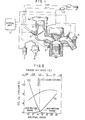
- Japanese Patent Laid-Open Nos. 69690/1977 and 72286/1977 disclose oxygen concentration measuring apparatus as generally shown in Fig. 3.
- this oxygen concentration measuring apparatus is composed of an oxygen ion-conductive solid electrolyte 11 of zirconia, first and second electrodes 12 and 13 formed on both sides of the slid electrolyte 11, a cover member 14 surrounding the first electrode 12, a gas diffusing aperture 15 and a diffusion chamber 16.
- a voltage E is applied between two electrodes such that the first electrode 12 serve as a cathode, and the quantity of flow of oxygen ions in the solid electrolyte is measured by an ampere meter 18.
- the sensor head composed of the electrolyte 11, electrodes 12, 13, cover member 14 and the gas diffusion aperture 15 is exposed to the hot gas to be examined (temperature 600 to 1000°C) and the voltage applied between both electrodes 12 and 13 is gradually increased.
- the increase of the voltage causes a corresponding increase in the electric current flowing between the electrodes 12 and 13 but this increase in the electric current is saturated and maintained constant when the voltage has been increased to a certain level.
- the relationship batweer the electric current and the voltage is shown in Fig. 3a.
- oxygen pumping phenomenon This can be attributable to a phenomenon called "oxygen pumping phenomenon" in which the oxygen introduced into the diffusion chamber 16 through the diffusion aperture 15 is reduced into oxygen ions by the first electrode 12, and the ions after being transmitted through the solid electrolyte 11 is oxidized again into oxygen upon reaching the second electrode.
- the saturation of the electric current is attributable to a restriction imposed by the diffusion aperture 15. Namely, the supply of the oxygen to be reduced into oxygen ions by the first electrode 12 is limited by the diffusion aperture 15.
- the electric current Ip changes substantially in proportion to the concentration of oxygen in the gas to be examined, as will be understood from the following formula (1).
- F represents the Faraday constant
- D represents the diffusion constant of oxygen
- R represents the gas constant
- T represents absolute temperature
- S represents the cross-sectional area of the gas diffusion aperture
- 2 represents the length of the gas diffusion aperture
- P0 2 represents the partial pressure of oxygen
- the conventional oxygen concentration measuring apparatus shown in Fig. 3 suffers from the following disadvantages.
- the cover member 14 is fixed to the zirconia solid electrolyte by bonding through a bond such as a glass flit, ceramics, glue or the like, so that the cover member 14 is liable to come off from the solid electrolyte 11 by a thermal impact, resulting in a secular change in the sensing performance.
- the sample a in which a ceramics bond is used showed a drastic increase of the output current Ip in quite a short time of use due to the separation of the cover member from the solid electrolyte which caused an increase in the gas permeation cross-sectional area equivalent to an increase in the cross-sectional area of the gas diffusion aperture 15.
- the sample a therefore, is not usable practically.
- Fig. 5 shoe's the time constant T , as measured with samples having gas-diffusion aperture diameters of 0.12 mm and 0.14 mm, while varying the depth h of the diffusion chamber.
- the diffusion chamber had equal cross-sectional area of 16 mm2 (4 mm high and 4 mm wide) and an equal diffusion aperture length of 0.4 mm.
- the time constant is on the order of several tens of microseconds (ms), and should not exceed 100 ms.
- the depth h of the diffusion chamber 16 is not greater than 50 ⁇ m which, however, is extremely difficult to attain because the thickness of the bond is not negligible.
- the practically obtainable time constant is, at the samllest, much greater than the desired value. From formula (2) mentioned before, it is readily understood that the time constant can be decreased as the diameter of the gas diffusion aperture 15 is increased.
- An experiment made by the inventors proved a fact that the effect of improvement in the response characteristic by the increase of the diameter of the diffusion aperture 15 is gradually decreased when the depth h of the diffusion chamber 16 approaches the diameter of the gas diffusion aperture 15. This may be attributed to a fact that the diffusion aperture 15 becomes close to the first electrode 12 as the-depth h of the diffusion chamber 16 is reduced so that the diffusion alor; the surface of the solid electrolyte is limited to an insufficient level.
- Fig. 6 shows the oxygene pumping current I as measured by the ampere meter 18 in relation to the voltage E applied between the first and the second electrodes 12 and 13, in the case of that the temperature of the gas to be examined is 800°C and the oxygen cocentration is 10%, for each of test sensors having diffusion aperture diameters of 0.12 mm and 0.24 mm.
- the pump current I is gradually increased as the voltage E applied between both electrodes becomes higher, and is saturated at a constant critical current Ip.
- this sensor relies upon the detection of this critical current Ip.
- a further increase in the voltage E applied causes a change from the ion-conductive state to an electron-conductive state of the zirconia solid electrolyte 11, thus allowing a drastic increase of the electric current.
- high precision of oxygen concentration measurement cannot be expected in this region where the electric current is increased drastically.
- the width Va of the region where the oxygen pumping current I is saturated and mantained substantially constant is increased as the diameter of the gas-diffusion aperture is increased, i.e., as the critical current Ip is increased.
- the margin voltage width Vb for the detection of the saturated electric current Ip becomes smaller as the diameter of the gas diffusion aperture 15 is increased. Since this margin Vb tends to become smaller due to a secular change, it is not allowed to make the margin Vb unlimitedly narrow from the view point of reliability.
- the improvement in the response characteristic by the increase of the diameter of the gas diffusion aperture 15 is limited also by this fact.
- the sensor is designed to exhibit a rather small critical current Ip. This is becuase the catalytic activities in the first and second electrodes 12 and 13 are practically limited. For information the data as shown in Fig. 6 has been obtained when the area of the electrode is 10 mm2.
- the value of the oxygen pumping current which can be converted per unit area was about 1 mA/rom2,
- the conventional oxygen concentration measuring apparatus encountered various problems coneern- ing the durability and response characteristics.
- an object of the invention is to provide an oxygen concentration measuring apparatus which does not suffer from small secular change in the output characteristics while ensuring a good response characteristics.
- the undesirable secular change in the output characteristics is avoided by a strong fixing of the cover member to the zirconia solid electrolyte attained by a process by laminating a zirconia solid electrolyte in the form of a green sheet and a cover member while they are in the un- fired state, heating and press-bonding the zirconia solid electrolyte and the cover member at a temperature of about 200°C, and effecting a firing to integrate the cover member to the zirconia solid electrolyte without using any adhesive or bond.
- the invention proposes also to form diffusion chambers of a depth not greater than several tens of micron meters (pm) by an organic binder burning method, while substituting a wide gas diffusion groove for the gas diffusion aperture in the conventional apparatus.
- Fig. 7 shows how the organic binder burning process is applied to the production of an oxygen concentration measuring apparatus of the conventional construction.
- a first electrode 12 and a second electrode 13 in the form of thick films are formed by printing on both sides of a zirconia solid electrolyte 11 in the form of a green sheet.
- an organic binder 19 containing carbon and other components is formed by printing on the electrode 12.
- a cover member 14 in the form of a green sheet having a gas diffusion aperture 15 formed therein by drilling is laminated to the electrolyte 11 through the intermediary of the organic binder 19.
- the laminated structure thus obtained is then subjected to a heat- and press-bonding conducted by means of a press at a temperature of about 200°C.
- the temperature is raised at a rate not greater than sevral degrees per minute so that the organic binder is gradually burnt and extinguished to leave a room corresponding to the diffusion chamber between two layers.
- the gases produced as a result of the burning of the organic binder is discharged to the outside through the gas diffusion aperture 15.
- the laminated structure is then subjected to a firing conducted at a temperature of about 1500°C, so that the solid electrolyte and the cover member 14 are uniformly sintered into one body.
- the boundary 20 between the zirconia solid electrolyte and the cover member is extinguished to allow a direct bonding of these two layers, while leaving a diffusion chamber 16 of a configuration substantially conforming with the form of the organic binder immediately after the heat- and press-bonding.
- the cover member 14 is made of a material having a thermal expansion coefficient substantially same as that of the zirconia solid electrolyte 11.
- the cover member 14 itself is made of the zirconia solid electrolyte.
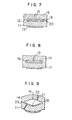
- Fig. 8 schematically show an example in which the cover member 14 is made of the ziconia solid electrolyte.
- the cross-sectional area of the gas diffusion aperture 15 is as small as 1/1000 or less of the cross-sectional area of the diffusion chamber 16, so that the rate of temperature rise during the burning of the organic binder has to be very small because otherwise the laminated structure is inflated due to a rise in the internal gas pressure in the portion corresponding to the diffusion chamber 16 during burning, resulting in the formation of pin-holes 21 and cracking 22 in the electrodes, while reducing the area of direct bond between the solid electrolyte 11 and the cover member 14 to allow an easy cracking by thermal impact, as shown in an exaggerated manner in Fig. 9.
- the sample b mentioned before in connection with Fig. 4 is an oxygen concentration sensor preapred by the methods explained above. Although this sample b exhibits a secular-change characteristics considerably improved as compared with the sample a, this sample b is still unsatisfactory from a view point of practicability.
- the secular change of this sample b is attributable to generation of micro-cracks in the bonding area and other portions due to a thermal impack as a result of an excessivee rise of the internal gas pressure during the burning of the organic binder 1 9 .
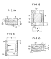
- Figs. 10 and 11 illustrate the basic arrangement for application of the organic binder burning method in the production of an oxygen concentration measuring apparatus of the invention. More specifically, Fig. 10 is a front elevational view of the arrangement, while Fig. 11 is a sectional view taken along the line XI-XI of Fig. 10.
- This arrangement is characterized in that at lease one of gas-diffusion grooves 24, 25, having a width and depth substantially equal to those of the diffusion chamber 16, is formed at both lateral sides of the electrode 12. Representing the width, length and depth of these grooves by W, L and H, respectively, the output current Ip of this sensor is about 2 times as large as that obtained by substituting L and HW for l and S in the formula (1) mentioned before.
- the diffusion chamber 16 and the diffusion 44057 grooves 24, 25 are formed by organic binder burning process similar to that explained before in connection with Fig. 7. Namely, after forming a layer of an organic binder by printing on the zirconia solid electrolyte 11 and the first electrode 12, a cover member 14 is placed and integrated with the zirconia electrolyte by heat- and press-bonding followed by burning.
- the breadth W of the gas diffusion grooves 24, 25 are substantially equal to that of the diffusion chamber 16, so that the rise of the internal gas pressure can be suppressed satisfactorily even with an appreciable rate of temperature rise during the burning.
- the depth h of the diffusion chamber is preferably around 10 micron meters ( ⁇ m), while the depth or the gas diffusion grooves 24 and 25 is about 20 micron meters ( ⁇ m) most preferably.
- the depth of the diffusion chamber is as small as several tens of micron meters ( ⁇ m) so that the internal volume Vp of the diffusion chamber can be made sufficiently small, so that a response characteristic or time constant on the order of several tens of microseconds (ms) or less, which is practically acceptable, can be obtained without substantial difficulty.
- Fig. 12 shows another embodiment of the invention in which the gas diffusion grooves 24, 25 have a width W smaller than that W * of the diffusion chamber 16. This embodiment also is free from the abnormal phenomenon encountered by the conventional arrangement during the burning of the organic binder. It has been confirmed that the products are practically usable when the width ratio W/W * is not smaller than 0.1, although this condition may varies depending on the length of the gas diffusion grooves 24, 25. Although not shown, other gas-diffusion grooves orthogonal to the grooves 24 and 25 may be formed in the portions marked by A and B in Fig. 12.
- Fig. 13 is a front elevational view of a still another embodiment of the oxygen concentration measuring apparatus of the invention.
- the gas diffusion groove 25 has a depth H which is smaller than the depth h of the diffusion chamber 16. It has been confirmed that, in the case of this embodiment, practically usable products are obtained generally on condition that the depth ratio H/h is not smaller than about 0.2.
- the zirconia solid electrolyte and the cover member are directly bonded and integrated with each other by an effective use of the organic binder burning process, regardless of any fluctuation in the burning conditions, so that oxygen concentration measuring apparatus having superior durability are produced stably.
- the internal volume of the diffusion chamber can be made sufficiently small, it is possible to obtain a high response characteristic on the order of less than several tens of microseconds (ms) in terms of time constant, cven with ;mall electric current.
Abstract
Description
- The present invention relates to an apparatus for measuring oxygen concentration and, more particularly, to an oxygen concentration measuring apparatus for measuring the oxygen concentration in exhaust gas emitted from an internal combustion engine. The invention relates also to a method of producing the oxygen concentration measuring apparatus.
- Modern internal combustion engines having an air-fuel ratio controller employ an air-fuel ratio sensor adapted to measure the oxygen concentration in the exhaust gas.
- Referring to Fig. 1, a typical air-fuel ratio controller has a
control unit 5 adapted to receive various information concerning the engine operation delivered by sensors such as an air-fuel ratio sensor 1, air-flow sensor 2, water-temperature sensor 3, and crank-position sensor 4. In response to these information, thecontrol unit 5 controls the operation of various devices such as afuel injector 6, ignition coil 7, idlespeed control valve 8, exhaust gas recirculation control valve 9 and afuel pump 10. - The air-fuel ratio sensor incorporated in this air-fuel ratio controller could measure only the stoichiometric air-fuel ratio, and the control of the air-fuel ratio is made to maintain the air-fuel ratio at the stoichiometric level, in order to reduce the noxious exhaust emissions. Fig. 2 shows how the concentrations of oxygen and carbon monoxide, as well as the combustion efficiency, are changed in relation to the air-fuel ratio. In the conventional air-fuel ratio controller, the control is made such as to maintain the stoichiometric air-fuel ratio (A/F = 14.7 excess-air ratio = 1), except the case where a specifically large power is required as in the case of acceleration in which a mixture richer than the stoichiometric one is set.
- On the other hand, it is well known that the maximum combustion efficiency is obtained by the leaner side of the stoichiometric level as will be seen from Fig. 2. From this point of view, it is desirable to control the air-fuel ratio such that the internal combustion engine operates on the leaner side of the stoichiometric air-fuel ratio. Such a control requires an air-fuel ratio sensor, i.e., an oxygen concentration measuring apparatus, capable of accurately detecting the air-fuel ratio.
- Oxygen concentration measuring apparatus have been known in which the oxygen concentration in exhaust emission is measured by making use of an oxygen pumping phenomenon exibited by an oxygen ion-conductive solid electrolyte. For instance, Japanese Patent Laid-Open Nos. 69690/1977 and 72286/1977 disclose oxygen concentration measuring apparatus as generally shown in Fig. 3.
- More specifically, this oxygen concentration measuring apparatus is composed of an oxygen ion-conductive
solid electrolyte 11 of zirconia, first andsecond electrodes slid electrolyte 11, acover member 14 surrounding thefirst electrode 12, agas diffusing aperture 15 and adiffusion chamber 16. In operation, a voltage E is applied between two electrodes such that thefirst electrode 12 serve as a cathode, and the quantity of flow of oxygen ions in the solid electrolyte is measured by anampere meter 18. - In the actual use of the oxygen concentration measuring apparatus of the type mentioned above, the sensor head composed of the
electrolyte 11,electrodes cover member 14 and thegas diffusion aperture 15 is exposed to the hot gas to be examined (temperature 600 to 1000°C) and the voltage applied between bothelectrodes electrodes - This can be attributable to a phenomenon called "oxygen pumping phenomenon" in which the oxygen introduced into the
diffusion chamber 16 through thediffusion aperture 15 is reduced into oxygen ions by thefirst electrode 12, and the ions after being transmitted through thesolid electrolyte 11 is oxidized again into oxygen upon reaching the second electrode. The saturation of the electric current is attributable to a restriction imposed by thediffusion aperture 15. Namely, the supply of the oxygen to be reduced into oxygen ions by thefirst electrode 12 is limited by thediffusion aperture 15. - According to this arrangement, when the voltage E is approximately 1 V, the electric current Ip changes substantially in proportion to the concentration of oxygen in the gas to be examined, as will be understood from the following formula (1)..

- where F represents the Faraday constant, D represents the diffusion constant of oxygen, R represents the gas constant, T represents absolute temperature, S represents the cross-sectional area of the gas diffusion aperture, 2 represents the length of the gas diffusion aperture and P02 represents the partial pressure of oxygen.
- Representing the internal volume of the diffusion chamber by Vr, the response characteristic of this senfor is approximately given by the following formula (2).

- The conventional oxygen concentration measuring apparatus shown in Fig. 3, however, suffers from the following disadvantages.
- The
cover member 14 is fixed to the zirconia solid electrolyte by bonding through a bond such as a glass flit, ceramics, glue or the like, so that thecover member 14 is liable to come off from thesolid electrolyte 11 by a thermal impact, resulting in a secular change in the sensing performance. - Fig. 4 shows the result of an experiment conducted to examine how the sensing characteristic is changed in relation to time. More specifically, this Figure shows how the output current Ip is changed in relation to time from a base level Ip = 1 obtained in the initial stage at temperature of 800°C when the oxygen concentration is 10%, for each of the samples a, b and c. The sample a in which a ceramics bond is used showed a drastic increase of the output current Ip in quite a short time of use due to the separation of the cover member from the solid electrolyte which caused an increase in the gas permeation cross-sectional area equivalent to an increase in the cross-sectional area of the
gas diffusion aperture 15. The sample a, therefore, is not usable practically. - The use of bond imposes another problem concerning the response characteristic as will be explained hereinunder with reference to Fig. 5.
- Fig. 5 shoe's the time constant T, as measured with samples having gas-diffusion aperture diameters of 0.12 mm and 0.14 mm, while varying the depth h of the diffusion chamber. In both cases, the diffusion chamber had equal cross-sectional area of 16 mm2 (4 mm high and 4 mm wide) and an equal diffusion aperture length of 0.4 mm. For attaining a high response characteristic of the control, it is desirable that the time constant is on the order of several tens of microseconds (ms), and should not exceed 100 ms. For obtaining such a small time constant, it is necessary that the depth h of the
diffusion chamber 16 is not greater than 50 µm which, however, is extremely difficult to attain because the thickness of the bond is not negligible. Consequently, the practically obtainable time constant is, at the samllest, much greater than the desired value. From formula (2) mentioned before, it is readily understood that the time constant can be decreased as the diameter of thegas diffusion aperture 15 is increased. An experiment made by the inventors, however, proved a fact that the effect of improvement in the response characteristic by the increase of the diameter of thediffusion aperture 15 is gradually decreased when the depth h of thediffusion chamber 16 approaches the diameter of thegas diffusion aperture 15. This may be attributed to a fact that thediffusion aperture 15 becomes close to thefirst electrode 12 as the-depth h of thediffusion chamber 16 is reduced so that the diffusion alor; the surface of the solid electrolyte is limited to an insufficient level. - Under these circumstances, the inventors attempted to improve the response characteristics by further increasing the diameter of the
gas diffusion aperture 15. However, as will be seen from Fig. 6 showing an E-I characteristic of the test sensor, it proved that there is a practical limit also in this method. More specifically, Fig. 6 shows the oxygene pumping current I as measured by theampere meter 18 in relation to the voltage E applied between the first and thesecond electrodes zirconia solid electrolyte 11, thus allowing a drastic increase of the electric current. Needless to say, high precision of oxygen concentration measurement cannot be expected in this region where the electric current is increased drastically. On the other hand, the width Va of the region where the oxygen pumping current I is saturated and mantained substantially constant is increased as the diameter of the gas-diffusion aperture is increased, i.e., as the critical current Ip is increased. This means that, when the voltage applied between two electrodes is maintained at a constant level of 1V, the margin voltage width Vb for the detection of the saturated electric current Ip becomes smaller as the diameter of thegas diffusion aperture 15 is increased. Since this margin Vb tends to become smaller due to a secular change, it is not allowed to make the margin Vb unlimitedly narrow from the view point of reliability. The improvement in the response characteristic by the increase of the diameter of thegas diffusion aperture 15 is limited also by this fact. As shown in Fig. 6, the sensor is designed to exhibit a rather small critical current Ip. This is becuase the catalytic activities in the first andsecond electrodes - Thus, the conventional oxygen concentration measuring apparatus encountered various problems coneern- ing the durability and response characteristics.
- Accordingly, an object of the invention is to provide an oxygen concentration measuring apparatus which does not suffer from small secular change in the output characteristics while ensuring a good response characteristics.
- To this end, according to the invention, the undesirable secular change in the output characteristics is avoided by a strong fixing of the cover member to the zirconia solid electrolyte attained by a process by laminating a zirconia solid electrolyte in the form of a green sheet and a cover member while they are in the un- fired state, heating and press-bonding the zirconia solid electrolyte and the cover member at a temperature of about 200°C, and effecting a firing to integrate the cover member to the zirconia solid electrolyte without using any adhesive or bond.
- In order to improve the response characteristics, the invention proposes also to form diffusion chambers of a depth not greater than several tens of micron meters (pm) by an organic binder burning method, while substituting a wide gas diffusion groove for the gas diffusion aperture in the conventional apparatus.
- The invention will be more fully described hereinunder with reference to the accompanying drawings.
- Fig. 1 is a schematic illustration of an air-fuel ratio controller of an internal combustion engine;
- Fig. 2 is an illustration showing how the contents of the exhaust gas and the combustion efficiency are changed in relation to the air-fuel ratio;
- Fig. 3 is an illustration of a conventional oxygen concentration measuring apparatus;
- Fig. 3a is a chart showing the current-voltage characteristics of the oxygen concentration measuring apparatus shown in Fig. 3;
- Fig. 4 is a chart showing the secular change of the operation characteristics;
- Fig. 5 is a chart showing the response characteristics of the conventional oxygen concentration measuring apparatus;
- Fig. 6 is a chart showing the E-I characteristic of a test sensor;
- Figs. 7 to 9 are illustrations of an organic binder burning process;
- Figs. 10 and 11 show the construction of an embodiment of the oxygen concentration measuring apparatus in accordance with the invention; and
- Figs. 12 and 13 are illustrations of another embodiment of the invention.
- A description will be made first as to the organic binder burning process which is used in the formation of the diffusion chamber and diffusion groove in the oxygen concentration measuring apparatus of the invention.
- Fig. 7 shows how the organic binder burning process is applied to the production of an oxygen concentration measuring apparatus of the conventional construction. A
first electrode 12 and asecond electrode 13 in the form of thick films are formed by printing on both sides of a zirconiasolid electrolyte 11 in the form of a green sheet. Then, anorganic binder 19 containing carbon and other components (thickness less than several tens of µm) is formed by printing on theelectrode 12. Acover member 14 in the form of a green sheet having agas diffusion aperture 15 formed therein by drilling is laminated to theelectrolyte 11 through the intermediary of theorganic binder 19. The laminated structure thus obtained is then subjected to a heat- and press-bonding conducted by means of a press at a temperature of about 200°C. Then, the temperature is raised at a rate not greater than sevral degrees per minute so that the organic binder is gradually burnt and extinguished to leave a room corresponding to the diffusion chamber between two layers. The gases produced as a result of the burning of the organic binder is discharged to the outside through thegas diffusion aperture 15. The laminated structure is then subjected to a firing conducted at a temperature of about 1500°C, so that the solid electrolyte and thecover member 14 are uniformly sintered into one body. Namely, theboundary 20 between the zirconia solid electrolyte and the cover member is extinguished to allow a direct bonding of these two layers, while leaving adiffusion chamber 16 of a configuration substantially conforming with the form of the organic binder immediately after the heat- and press-bonding. Taking into the thermal stress into consideration, it is necessary that thecover member 14 is made of a material having a thermal expansion coefficient substantially same as that of the zirconiasolid electrolyte 11. Preferably, thecover member 14 itself is made of the zirconia solid electrolyte. Fig. 8 schematically show an example in which thecover member 14 is made of the ziconia solid electrolyte. - The cross-sectional area of the
gas diffusion aperture 15 is as small as 1/1000 or less of the cross-sectional area of thediffusion chamber 16, so that the rate of temperature rise during the burning of the organic binder has to be very small because otherwise the laminated structure is inflated due to a rise in the internal gas pressure in the portion corresponding to thediffusion chamber 16 during burning, resulting in the formation of pin-holes 21 and cracking 22 in the electrodes, while reducing the area of direct bond between thesolid electrolyte 11 and thecover member 14 to allow an easy cracking by thermal impact, as shown in an exaggerated manner in Fig. 9. - It would be possible to suppress any exessive rise of the internal gas pressure by increasing the number of the
gas diffusion apertures 15 and the cross-sectional area thereof. In this case, however, it is not allowed to increase the number of the apertures and cross-sectional area unlimitedly because the capacity of the oxygen pumping function of the electrodes is limited. - Thus, when the organic binder burning method is applied to the conventional oxygen concentration measuring apparatus, it is quite important to stabilize the conditions or factors such as the rate of temperature rise during the burning, which is generally difficult to attain.
- The sample b mentioned before in connection with Fig. 4 is an oxygen concentration sensor preapred by the methods explained above. Although this sample b exhibits a secular-change characteristics considerably improved as compared with the sample a, this sample b is still unsatisfactory from a view point of practicability. The secular change of this sample b is attributable to generation of micro-cracks in the bonding area and other portions due to a thermal impack as a result of an excesive rise of the internal gas pressure during the burning of the organic binder 19.
- These problems, however, are overcome by the present invention as will be understood from the following description.
- Figs. 10 and 11 illustrate the basic arrangement for application of the organic binder burning method in the production of an oxygen concentration measuring apparatus of the invention. More specifically, Fig. 10 is a front elevational view of the arrangement, while Fig. 11 is a sectional view taken along the line XI-XI of Fig. 10. This arrangement is characterized in that at lease one of gas-
diffusion grooves diffusion chamber 16, is formed at both lateral sides of theelectrode 12. Representing the width, length and depth of these grooves by W, L and H, respectively, the output current Ip of this sensor is about 2 times as large as that obtained by substituting L and HW for ℓ and S in the formula (1) mentioned before. According to this arrangement, it is possible to obtain a small depth H of thediffusion groove second electrodes - The diffusion chamber 16 and the diffusion 44057
grooves solid electrolyte 11 and thefirst electrode 12, acover member 14 is placed and integrated with the zirconia electrolyte by heat- and press-bonding followed by burning. The breadth W of thegas diffusion grooves diffusion chamber 16, so that the rise of the internal gas pressure can be suppressed satisfactorily even with an appreciable rate of temperature rise during the burning. - Therefore, the undesirable effect explained before in connection with Fig. 9 such as an inflation of the diffusion chamber, pin-holes and minute cracks are eliminated regardless of any slight fluctuation in the burning conditions or factors. A sample produced by this process showed an extremely small secular change as shown by a curve c in Fig. 4.
- The thickness of printed film of organic binder can be varied within the range of between several microns to about ten of micron meters (pm) in each printing step. Therefore, the depths of the
gas diffusion grooves diffusion chamber 16 on the order of several tens of micron meters (µm) can be obtained by repeating the printing of the organic binder for several times. The first and thesecond electrodes gas diffusion grooves - According to the invention, the depth of the diffusion chamber is as small as several tens of micron meters (µm) so that the internal volume Vp of the diffusion chamber can be made sufficiently small, so that a response characteristic or time constant on the order of several tens of microseconds (ms) or less, which is practically acceptable, can be obtained without substantial difficulty.
- Fig. 12 shows another embodiment of the invention in which the
gas diffusion grooves diffusion chamber 16. This embodiment also is free from the abnormal phenomenon encountered by the conventional arrangement during the burning of the organic binder. It has been confirmed that the products are practically usable when the width ratio W/W* is not smaller than 0.1, although this condition may varies depending on the length of thegas diffusion grooves grooves - Fig. 13 is a front elevational view of a still another embodiment of the oxygen concentration measuring apparatus of the invention. In this embodiment, the
gas diffusion groove 25 has a depth H which is smaller than the depth h of thediffusion chamber 16. It has been confirmed that, in the case of this embodiment, practically usable products are obtained generally on condition that the depth ratio H/h is not smaller than about 0.2. - As will be understood from the foregoing description, according to the invention, the zirconia solid electrolyte and the cover member are directly bonded and integrated with each other by an effective use of the organic binder burning process, regardless of any fluctuation in the burning conditions, so that oxygen concentration measuring apparatus having superior durability are produced stably. In addition, since the internal volume of the diffusion chamber can be made sufficiently small, it is possible to obtain a high response characteristic on the order of less than several tens of microseconds (ms) in terms of time constant, cven with ;mall electric current.
Claims (4)
Applications Claiming Priority (2)
| Application Number | Priority Date | Filing Date | Title |
|---|---|---|---|
| JP58223941A JPH0612354B2 (en) | 1983-11-28 | 1983-11-28 | Method for manufacturing oxygen concentration measuring device |
| JP223941/83 | 1983-11-28 |
Publications (3)
| Publication Number | Publication Date |
|---|---|
| EP0144057A2 true EP0144057A2 (en) | 1985-06-12 |
| EP0144057A3 EP0144057A3 (en) | 1987-07-15 |
| EP0144057B1 EP0144057B1 (en) | 1991-04-03 |
Family
ID=16806098
Family Applications (1)
| Application Number | Title | Priority Date | Filing Date |
|---|---|---|---|
| EP84114331A Expired - Lifetime EP0144057B1 (en) | 1983-11-28 | 1984-11-27 | Apparatus for measuring oxygen concentration and method of producing the appartus |
Country Status (6)
| Country | Link |
|---|---|
| EP (1) | EP0144057B1 (en) |
| JP (1) | JPH0612354B2 (en) |
| KR (1) | KR910004156B1 (en) |
| CN (1) | CN1003541B (en) |
| CA (1) | CA1222285A (en) |
| DE (1) | DE3484383D1 (en) |
Cited By (14)
| Publication number | Priority date | Publication date | Assignee | Title |
|---|---|---|---|---|
| EP0148622A2 (en) * | 1983-12-24 | 1985-07-17 | Ngk Insulators, Ltd. | Process of manufacturing electrochemical device |
| DE3626162A1 (en) * | 1985-08-02 | 1987-02-12 | Hitachi Ltd | AIR FUEL RATIO DETECTING SYSTEM FOR AN ENGINE EXHAUST GAS |
| DE3702838A1 (en) * | 1986-02-01 | 1987-08-13 | Fuji Electric Co Ltd | OXYGEN SENSOR AND METHOD FOR THE PRODUCTION THEREOF |
| DE3707874A1 (en) * | 1986-03-11 | 1987-09-17 | Nissan Motor | AIR / FUEL RATIO SENSOR WITH AN OXYGEN SENSOR CELL AND AN OXYGEN PUMP CELL |
| EP0273304A2 (en) * | 1986-12-19 | 1988-07-06 | Matsushita Electric Industrial Co., Ltd. | Oxygen sensor |
| EP0281375A2 (en) * | 1987-03-04 | 1988-09-07 | Westinghouse Electric Corporation | Oxygen analyzer |
| FR2620868A1 (en) * | 1987-09-22 | 1989-03-24 | Thomson Csf | PROCESS FOR PRODUCING MICROCAVITIES AND APPLICATION TO AN ELECTROCHEMICAL SENSOR AND A GAS PHASE CHOMATOGRAPH |
| EP0366863A2 (en) * | 1988-10-31 | 1990-05-09 | Fujikura Ltd. | An oxygen sensor device |
| EP0516038A2 (en) * | 1991-05-27 | 1992-12-02 | Nippondenso Co., Ltd. | Oxygen concentration sensor |
| DE3990187C2 (en) * | 1988-02-24 | 1993-11-25 | Matsushita Electric Works Ltd | Electrochemical gas sensor |
| WO1994025864A1 (en) * | 1993-04-23 | 1994-11-10 | Robert Bosch Gmbh | Sensor unit for determining the gas component concentration |
| FR2710750A1 (en) * | 1993-09-30 | 1995-04-07 | Bosch Gmbh Robert | Electrochemical measuring sensor for determining the oxygen content in gases. |
| WO1995015490A1 (en) * | 1993-12-01 | 1995-06-08 | Robert Bosch Gmbh | Oxygen sensor |
| WO2006084836A1 (en) * | 2005-02-14 | 2006-08-17 | Robert Bosch Gmbh | Gas sensor |
Families Citing this family (6)
| Publication number | Priority date | Publication date | Assignee | Title |
|---|---|---|---|---|
| JPH0623727B2 (en) * | 1985-08-30 | 1994-03-30 | 日本碍子株式会社 | Electrochemical device and method for manufacturing the same |
| JPS62285055A (en) * | 1986-06-03 | 1987-12-10 | Fuji Electric Co Ltd | Oxygen sensor |
| JPS62201057U (en) * | 1986-06-13 | 1987-12-22 | ||
| JPS62285056A (en) * | 1986-06-03 | 1987-12-10 | Fuji Electric Co Ltd | Manufacture of oxygen sensor |
| JPS6383653U (en) * | 1986-11-20 | 1988-06-01 | ||
| CN115166000A (en) * | 2022-06-21 | 2022-10-11 | 湖北天瑞电子股份有限公司 | Sensor chip for fuel inerting oxygen measurement and preparation method thereof |
Citations (7)
| Publication number | Priority date | Publication date | Assignee | Title |
|---|---|---|---|---|
| FR2334101A1 (en) * | 1975-12-05 | 1977-07-01 | Westinghouse Electric Corp | GAS ANALYSIS APPARATUS |
| EP0011530A1 (en) * | 1978-11-21 | 1980-05-28 | Thomson-Csf | Electrochemical sensor of relative concentrations of reactive substances in a fluid mixture, manufacturing process of the sensor and a system comprising such a sensor, especially for control |
| EP0020938A1 (en) * | 1979-06-09 | 1981-01-07 | Robert Bosch Gmbh | Polarographic sensor for determining the oxygen content in gases, especially in exhaust gases of internal-combustion engines |
| EP0035400A1 (en) * | 1980-03-03 | 1981-09-09 | Ford Motor Company Limited | Apparatus and method for measuring the partial pressure of a gas |
| US4381224A (en) * | 1981-04-27 | 1983-04-26 | Ford Motor Company | Step function lean burn oxygen sensor |
| EP0104636A2 (en) * | 1982-09-28 | 1984-04-04 | Fuji Electric Corporate Research And Development Ltd. | Oxygen sensor and process for producing the same |
| EP0140295A2 (en) * | 1983-10-19 | 1985-05-08 | Hitachi, Ltd. | Method of operating an air-fuel ratio sensor |
Family Cites Families (4)
| Publication number | Priority date | Publication date | Assignee | Title |
|---|---|---|---|---|
| JPS5272286A (en) * | 1975-12-12 | 1977-06-16 | Toyoda Chuo Kenkyusho Kk | Oxygen concentration analyzer |
| DE3017947A1 (en) * | 1980-05-10 | 1981-11-12 | Bosch Gmbh Robert | ELECTROCHEMICAL SENSOR FOR DETERMINING THE OXYGEN CONTENT IN GAS AND METHOD FOR PRODUCING SENSOR ELEMENTS FOR SUCH SENSOR |
| DE3104986A1 (en) * | 1981-02-12 | 1982-08-19 | Bosch Gmbh Robert | Polarographic sensor for the determination of the oxygen content of gases |
| JPS58130261U (en) * | 1982-02-26 | 1983-09-02 | 日本特殊陶業株式会社 | oxygen sensor |
-
1983
- 1983-11-28 JP JP58223941A patent/JPH0612354B2/en not_active Expired - Lifetime
-
1984
- 1984-11-21 KR KR8407279A patent/KR910004156B1/en not_active IP Right Cessation
- 1984-11-27 CA CA000468718A patent/CA1222285A/en not_active Expired
- 1984-11-27 EP EP84114331A patent/EP0144057B1/en not_active Expired - Lifetime
- 1984-11-27 DE DE8484114331T patent/DE3484383D1/en not_active Expired - Lifetime
-
1985
- 1985-04-01 CN CN85101228.0A patent/CN1003541B/en not_active Expired
Patent Citations (7)
| Publication number | Priority date | Publication date | Assignee | Title |
|---|---|---|---|---|
| FR2334101A1 (en) * | 1975-12-05 | 1977-07-01 | Westinghouse Electric Corp | GAS ANALYSIS APPARATUS |
| EP0011530A1 (en) * | 1978-11-21 | 1980-05-28 | Thomson-Csf | Electrochemical sensor of relative concentrations of reactive substances in a fluid mixture, manufacturing process of the sensor and a system comprising such a sensor, especially for control |
| EP0020938A1 (en) * | 1979-06-09 | 1981-01-07 | Robert Bosch Gmbh | Polarographic sensor for determining the oxygen content in gases, especially in exhaust gases of internal-combustion engines |
| EP0035400A1 (en) * | 1980-03-03 | 1981-09-09 | Ford Motor Company Limited | Apparatus and method for measuring the partial pressure of a gas |
| US4381224A (en) * | 1981-04-27 | 1983-04-26 | Ford Motor Company | Step function lean burn oxygen sensor |
| EP0104636A2 (en) * | 1982-09-28 | 1984-04-04 | Fuji Electric Corporate Research And Development Ltd. | Oxygen sensor and process for producing the same |
| EP0140295A2 (en) * | 1983-10-19 | 1985-05-08 | Hitachi, Ltd. | Method of operating an air-fuel ratio sensor |
Cited By (23)
| Publication number | Priority date | Publication date | Assignee | Title |
|---|---|---|---|---|
| EP0148622B1 (en) * | 1983-12-24 | 1988-11-17 | Ngk Insulators, Ltd. | Process of manufacturing electrochemical device |
| EP0148622A2 (en) * | 1983-12-24 | 1985-07-17 | Ngk Insulators, Ltd. | Process of manufacturing electrochemical device |
| DE3626162A1 (en) * | 1985-08-02 | 1987-02-12 | Hitachi Ltd | AIR FUEL RATIO DETECTING SYSTEM FOR AN ENGINE EXHAUST GAS |
| DE3702838A1 (en) * | 1986-02-01 | 1987-08-13 | Fuji Electric Co Ltd | OXYGEN SENSOR AND METHOD FOR THE PRODUCTION THEREOF |
| DE3707874A1 (en) * | 1986-03-11 | 1987-09-17 | Nissan Motor | AIR / FUEL RATIO SENSOR WITH AN OXYGEN SENSOR CELL AND AN OXYGEN PUMP CELL |
| EP0273304A2 (en) * | 1986-12-19 | 1988-07-06 | Matsushita Electric Industrial Co., Ltd. | Oxygen sensor |
| EP0273304B1 (en) * | 1986-12-19 | 1992-07-15 | Matsushita Electric Industrial Co., Ltd. | Oxygen sensor |
| EP0281375A2 (en) * | 1987-03-04 | 1988-09-07 | Westinghouse Electric Corporation | Oxygen analyzer |
| EP0281375A3 (en) * | 1987-03-04 | 1989-11-29 | Westinghouse Electric Corporation | Oxygen analyzer |
| FR2620868A1 (en) * | 1987-09-22 | 1989-03-24 | Thomson Csf | PROCESS FOR PRODUCING MICROCAVITIES AND APPLICATION TO AN ELECTROCHEMICAL SENSOR AND A GAS PHASE CHOMATOGRAPH |
| EP0309334A1 (en) * | 1987-09-22 | 1989-03-29 | Thomson-Csf | Method for producing microcavities and use in an electrochemical sensor and in a gas chromatograph |
| US4956073A (en) * | 1987-09-22 | 1990-09-11 | Thomson-Csf | Method to make microcavities and its application to an electrochemical sensor |
| US5087275A (en) * | 1987-09-22 | 1992-02-11 | Thomson-Csf | Electrochemical sensor having microcavities |
| DE3990187C2 (en) * | 1988-02-24 | 1993-11-25 | Matsushita Electric Works Ltd | Electrochemical gas sensor |
| EP0366863A2 (en) * | 1988-10-31 | 1990-05-09 | Fujikura Ltd. | An oxygen sensor device |
| EP0366863A3 (en) * | 1988-10-31 | 1991-05-29 | Fujikura Ltd. | An oxygen sensor device |
| EP0516038A2 (en) * | 1991-05-27 | 1992-12-02 | Nippondenso Co., Ltd. | Oxygen concentration sensor |
| EP0516038A3 (en) * | 1991-05-27 | 1993-12-15 | Nippon Denso Co | Oxygen concentration sensor |
| WO1994025864A1 (en) * | 1993-04-23 | 1994-11-10 | Robert Bosch Gmbh | Sensor unit for determining the gas component concentration |
| US5545301A (en) * | 1993-04-23 | 1996-08-13 | Robert Bosch Gmbh | Sensor element for the determination of concentration of gas constituent(s) |
| FR2710750A1 (en) * | 1993-09-30 | 1995-04-07 | Bosch Gmbh Robert | Electrochemical measuring sensor for determining the oxygen content in gases. |
| WO1995015490A1 (en) * | 1993-12-01 | 1995-06-08 | Robert Bosch Gmbh | Oxygen sensor |
| WO2006084836A1 (en) * | 2005-02-14 | 2006-08-17 | Robert Bosch Gmbh | Gas sensor |
Also Published As
| Publication number | Publication date |
|---|---|
| KR910004156B1 (en) | 1991-06-22 |
| EP0144057B1 (en) | 1991-04-03 |
| CN85101228A (en) | 1987-01-10 |
| EP0144057A3 (en) | 1987-07-15 |
| KR850003792A (en) | 1985-06-26 |
| JPS60114762A (en) | 1985-06-21 |
| CN1003541B (en) | 1989-03-08 |
| DE3484383D1 (en) | 1991-05-08 |
| CA1222285A (en) | 1987-05-26 |
| JPH0612354B2 (en) | 1994-02-16 |
Similar Documents
| Publication | Publication Date | Title |
|---|---|---|
| EP0144057A2 (en) | Apparatus for measuring oxygen concentration and method of producing the appartus | |
| US4300991A (en) | Air-fuel ratio detecting apparatus | |
| US4304652A (en) | Device for detection of air/fuel ratio from oxygen partial pressure in exhaust gas | |
| US5288389A (en) | Oxygen sensor with higher resistance to repeated thermal-shocks and shorter warm-up time | |
| EP0142993B1 (en) | Electrochemical device | |
| EP1074834B1 (en) | Method and apparatus for measuring NOx gas concentration | |
| US4574627A (en) | Air-fuel ratio detector and method of measuring air-fuel ratio | |
| US5098549A (en) | Sensor element for limiting current sensors for determining the λ value of gas mixtures | |
| JP3107817B2 (en) | Sensor element for limiting current sensor for detection of λ value of mixed gas | |
| US4882033A (en) | Electrochemical device | |
| EP0987546B1 (en) | Gas concentration sensing apparatus | |
| EP0142992A1 (en) | Electrochemical device incorporating a sensing element | |
| KR900700879A (en) | Planar polarizer graphic probe for determining exhaust gas λ value of internal combustion engine and its manufacturing method | |
| JPS61147155A (en) | Electrochemical device | |
| US4836906A (en) | Air-fuel ratio sensor | |
| KR890000080B1 (en) | Method for detecting an air-fuel ratio | |
| CA1248198A (en) | Air-fuel ratio sensor used to control an internal combustion engine | |
| US6254765B1 (en) | Method of regulating the temperature of a sensor | |
| JPH0260142B2 (en) | ||
| JP3827721B2 (en) | Electrochemical sensor for measuring nitrogen oxides in gas mixtures | |
| Soejima et al. | Multi-layered zirconia oxygen sensor for lean burn engine application | |
| US6949175B2 (en) | Gas sensing element | |
| US4747930A (en) | Air/fuel ratio sensor | |
| EP0193379B1 (en) | Air/fuel ratio sensor | |
| US5972200A (en) | Method for driving a wide range air to fuel ratio sensor |
Legal Events
| Date | Code | Title | Description |
|---|---|---|---|
| PUAI | Public reference made under article 153(3) epc to a published international application that has entered the european phase |
Free format text: ORIGINAL CODE: 0009012 |
|
| AK | Designated contracting states |
Designated state(s): CH DE FR GB IT LI NL SE |
|
| PUAL | Search report despatched |
Free format text: ORIGINAL CODE: 0009013 |
|
| AK | Designated contracting states |
Kind code of ref document: A3 Designated state(s): CH DE FR GB IT LI NL SE |
|
| 17P | Request for examination filed |
Effective date: 19870717 |
|
| 17Q | First examination report despatched |
Effective date: 19881102 |
|
| GRAA | (expected) grant |
Free format text: ORIGINAL CODE: 0009210 |
|
| RBV | Designated contracting states (corrected) |
Designated state(s): DE FR GB |
|
| AK | Designated contracting states |
Kind code of ref document: B1 Designated state(s): DE FR GB |
|
| REF | Corresponds to: |
Ref document number: 3484383 Country of ref document: DE Date of ref document: 19910508 |
|
| ET | Fr: translation filed | ||
| PGFP | Annual fee paid to national office [announced via postgrant information from national office to epo] |
Ref country code: FR Payment date: 19910930 Year of fee payment: 8 |
|
| PGFP | Annual fee paid to national office [announced via postgrant information from national office to epo] |
Ref country code: GB Payment date: 19911115 Year of fee payment: 8 |
|
| PLBE | No opposition filed within time limit |
Free format text: ORIGINAL CODE: 0009261 |
|
| STAA | Information on the status of an ep patent application or granted ep patent |
Free format text: STATUS: NO OPPOSITION FILED WITHIN TIME LIMIT |
|
| 26N | No opposition filed | ||
| PG25 | Lapsed in a contracting state [announced via postgrant information from national office to epo] |
Ref country code: GB Effective date: 19921127 |
|
| GBPC | Gb: european patent ceased through non-payment of renewal fee |
Effective date: 19921127 |
|
| PG25 | Lapsed in a contracting state [announced via postgrant information from national office to epo] |
Ref country code: FR Effective date: 19930730 |
|
| REG | Reference to a national code |
Ref country code: FR Ref legal event code: ST |
|
| PGFP | Annual fee paid to national office [announced via postgrant information from national office to epo] |
Ref country code: DE Payment date: 20001229 Year of fee payment: 17 |
|
| PG25 | Lapsed in a contracting state [announced via postgrant information from national office to epo] |
Ref country code: DE Free format text: LAPSE BECAUSE OF NON-PAYMENT OF DUE FEES Effective date: 20020702 |