EP0366648B1 - Mecanisme d'entrainement pour laminoirs a pas de pelerin froids - Google Patents
Mecanisme d'entrainement pour laminoirs a pas de pelerin froids Download PDFInfo
- Publication number
- EP0366648B1 EP0366648B1 EP87903858A EP87903858A EP0366648B1 EP 0366648 B1 EP0366648 B1 EP 0366648B1 EP 87903858 A EP87903858 A EP 87903858A EP 87903858 A EP87903858 A EP 87903858A EP 0366648 B1 EP0366648 B1 EP 0366648B1
- Authority
- EP
- European Patent Office
- Prior art keywords
- crank
- connecting rod
- drive mechanism
- mass
- pinion
- Prior art date
- Legal status (The legal status is an assumption and is not a legal conclusion. Google has not performed a legal analysis and makes no representation as to the accuracy of the status listed.)
- Expired - Lifetime
Links
Images


Classifications
-
- B—PERFORMING OPERATIONS; TRANSPORTING
- B21—MECHANICAL METAL-WORKING WITHOUT ESSENTIALLY REMOVING MATERIAL; PUNCHING METAL
- B21B—ROLLING OF METAL
- B21B21/00—Pilgrim-step tube-rolling, i.e. pilger mills
- B21B21/005—Pilgrim-step tube-rolling, i.e. pilger mills with reciprocating stand, e.g. driving the stand
Definitions
- the invention relates to a drive for a cold pilger rolling mill with mass and moment compensation according to the preamble of claim 1.
- Such a cold pilger rolling mill is known from DE-AS-27 40 729, the crank mechanism being arranged laterally offset from the rolling mill.
- the crank is connected via a crankshaft crank to the balancing mass for torque compensation arranged above the crank mechanism. This is 90 ° out of phase with the crank, and the reciprocating movement is made possible by parallel guides.
- the rolling mill itself is coupled via a long connecting rod, which is supported on the crankshaft crank on one side.
- the object of the invention is to develop a compact, cost-effective and as little stressed design for the drive from the existing knowledge about the mass and torque compensation of the double slide.
- the overall vertical design makes it possible for the rolling stand to engage on one side and thus be guided over the entire gear unit. This eliminates the need for a connecting rod that connects the roll stand to the gear unit.
- the paddock engages the slide directly below the roll stand.
- the mass required for torque compensation is provided by the coupling itself.
- the center of gravity of the paddock was placed beyond point D of the positive guidance.
- the total mass of the coupling is reduced to point D, which in turn keeps the dimensions of the coupling small (flat design).
- the paddock rotates with it and contributes with its moment of inertia ⁇ Ko to an improved uniformity of the overall system. Due to the design and arrangement of the coupling, the focal planes of torque compensation, mass compensation and the roll stand are brought together as closely as possible. This results in a compact design and a relatively low load within the gear unit.
- the slide guide and positive guide are approximately in the same plane. This was made possible by an interruption in the forced operation.
- the positive guidance is only required in the end positions in order to maintain the direction of rotation of the coupling and crank.
- the embodiment according to claim 3 represents a modified embodiment, namely with a planetary crank gear (PKG).
- the structure of the PKG is almost identical to the previously described first version of a double slide gear (DG).
- the difference to the DG is that there is no forced guidance.
- This is replaced by a planetary gear, which consists of a pinion and an internally toothed gear.
- the pinion is firmly connected to the crank pin and rolls on the external internal teeth due to the rotating movement of the crank.
- the superimposition of the rotational movement of the pinion and crank results in an exactly opposite direction of rotation of the coupling.
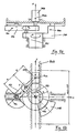
- the rolling stand (WG) can be moved in a slide guide (Sch).
- the roll stand is connected to the coupling (KO), which is arranged below the roll stand, and runs about a vertical axis via a pin.
- the coupling (KO) has a cam roller (1), by means of which the coupling (KO) is guided in positive guides (2).
- these positive guides (2) are only provided in the area of the end positions of the cam roller (1) or the coupling (KO).
- the coupling (KO) is connected to the crank (KU) via the crank pin (3).
- Figure lb shows the movements of the crank (KU), coupling (KO) and slide (4) (ie the rolling stand).
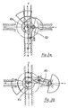
- FIGS. 3a and b which show the coupling (KO) and the crank (KU) in different positions relative to one another, also serve for a better understanding of the movement sequence.
- the crank (KU) is connected to the drive (8) (not shown) via a corresponding toothing (5-7).
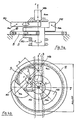
- the second embodiment shown in FIGS. 4a, b and 5 differs from the first embodiment in that a planetary crank arrangement is provided instead of the positive guides.
Landscapes
- Engineering & Computer Science (AREA)
- Mechanical Engineering (AREA)
- Transmission Devices (AREA)
- Retarders (AREA)
- Metal Rolling (AREA)
Claims (3)
caractérisé en ce que
la cage de laminoir (WG) est agencée directement au-dessus de la commande à manivelle (KU) et la bielle (KO) est montée directement sur le tourillon de manivelle (3), la bielle (KO) avec sa masse totale assumant l'équilibrage de couple et la manivelle (KU) avec sa masse totale assumant l'équilibrage de masse .
caractérisé en ce que
la bielle (KO) est guidée, dans la zone des positions extrêmes de mouvement, dans des guidages forcés.
caractérisé en ce que
la manivelle (KU) est réalisée en tant que partie d'un engrenage planétaire, en ce qu'un pignon (9) est agencé sur le tourillon de manivelle (3), en étant solidaire de celui-ci, pignon qui roule sur une roue (10) dentée intérieurement et entourant la manivelle (KU), de sorte que, par superposition du mouvement rotatif du pignon et de la manivelle (KU), la bielle (KO) conserve un mouvement rotatif opposé.
Priority Applications (2)
| Application Number | Priority Date | Filing Date | Title |
|---|---|---|---|
| AT87903858T ATE71315T1 (de) | 1986-04-15 | 1987-06-18 | Antrieb fuer ein kaltpilgerwalzwerk. |
| SU894742630A RU1799299C (ru) | 1987-06-18 | 1989-12-15 | Стан холодной прокатки труб |
Applications Claiming Priority (3)
| Application Number | Priority Date | Filing Date | Title |
|---|---|---|---|
| DE3613036A DE3613036C1 (en) | 1986-04-15 | 1986-04-15 | Drive for cold pilger roll mill |
| PCT/DE1987/000277 WO1988010160A1 (fr) | 1986-04-15 | 1987-06-18 | Mecanisme d'entrainement pour laminoirs a pas de pelerin froids |
| CA000540656A CA1327134C (fr) | 1986-04-15 | 1987-06-26 | Systeme d'entrainement pour laminoir pas de pelerin a froid |
Publications (2)
| Publication Number | Publication Date |
|---|---|
| EP0366648A1 EP0366648A1 (fr) | 1990-05-09 |
| EP0366648B1 true EP0366648B1 (fr) | 1992-01-08 |
Family
ID=25671397
Family Applications (1)
| Application Number | Title | Priority Date | Filing Date |
|---|---|---|---|
| EP87903858A Expired - Lifetime EP0366648B1 (fr) | 1986-04-15 | 1987-06-18 | Mecanisme d'entrainement pour laminoirs a pas de pelerin froids |
Country Status (5)
| Country | Link |
|---|---|
| EP (1) | EP0366648B1 (fr) |
| JP (1) | JPH07108407B2 (fr) |
| AT (1) | ATE71315T1 (fr) |
| DE (1) | DE3613036C1 (fr) |
| WO (1) | WO1988010160A1 (fr) |
Families Citing this family (9)
| Publication number | Priority date | Publication date | Assignee | Title |
|---|---|---|---|---|
| DE3613036C1 (en) * | 1986-04-15 | 1987-08-13 | Mannesmann Ag | Drive for cold pilger roll mill |
| DE3706129C1 (de) * | 1987-02-23 | 1988-03-10 | Mannesmann Ag | Antrieb fuer ein Kaltpilgerwalzwerk mit Massen- und Momentenausgleich |
| DE10147046C2 (de) * | 2001-09-25 | 2003-10-02 | Sms Meer Gmbh | Antriebssystem für ein Walzwerk |
| DE10241612B3 (de) * | 2002-09-07 | 2004-01-08 | Sms Meer Gmbh | Antriebssystem für ein Kaltpilgerwalzwerk |
| DE10311144B3 (de) * | 2003-03-14 | 2004-10-28 | Sms Meer Gmbh | Verfahren zum Herstellen eines Rohres mit einer Innenprofilierung und Vorrichtung zur Durchführung des Verfahrens |
| RU2271257C2 (ru) * | 2003-12-01 | 2006-03-10 | Открытое акционерное общество "Электростальский завод тяжелого машиностроения" | Привод стана холодной пильгерной прокатки труб |
| DE102009007465B3 (de) | 2009-02-04 | 2010-09-30 | Sms Meer Gmbh | Antriebssystem für ein Walzwerk, insbesondere für ein Kaltpilgerwalzwerk |
| RU2422221C2 (ru) * | 2009-06-15 | 2011-06-27 | Открытое акционерное общество "Электростальский завод тяжелого машиностроения" | Многовалковая клеть |
| RU2414975C1 (ru) * | 2009-09-08 | 2011-03-27 | Открытое акционерное общество "Электростальский завод тяжелого машиностроения" | Стан холодной прокатки труб |
Family Cites Families (5)
| Publication number | Priority date | Publication date | Assignee | Title |
|---|---|---|---|---|
| US2541324A (en) * | 1945-04-20 | 1951-02-13 | Bell Telephone Labor Inc | Motion translating mechanism |
| US4052898A (en) * | 1976-09-13 | 1977-10-11 | Wean United, Inc. | Crank drive system for cold pilger mills drive or the like |
| SU735342A1 (ru) * | 1977-01-28 | 1980-05-27 | Днепропетровский Ордена Трудового Красного Знамени Металлургический Институт | Привод клети стана холодной прокатки труб |
| SU956081A1 (ru) * | 1980-12-11 | 1982-09-07 | Уральский ордена Трудового Красного Знамени политехнический институт им.С.М.Кирова | Привод перемещени рабочей клети стана холодной прокатки труб |
| DE3613036C1 (en) * | 1986-04-15 | 1987-08-13 | Mannesmann Ag | Drive for cold pilger roll mill |
-
1986
- 1986-04-15 DE DE3613036A patent/DE3613036C1/de not_active Expired
-
1987
- 1987-06-18 AT AT87903858T patent/ATE71315T1/de not_active IP Right Cessation
- 1987-06-18 JP JP62503592A patent/JPH07108407B2/ja not_active Expired - Lifetime
- 1987-06-18 EP EP87903858A patent/EP0366648B1/fr not_active Expired - Lifetime
- 1987-06-18 WO PCT/DE1987/000277 patent/WO1988010160A1/fr not_active Ceased
Also Published As
| Publication number | Publication date |
|---|---|
| JPH07108407B2 (ja) | 1995-11-22 |
| ATE71315T1 (de) | 1992-01-15 |
| EP0366648A1 (fr) | 1990-05-09 |
| DE3613036C1 (en) | 1987-08-13 |
| JPH03501362A (ja) | 1991-03-28 |
| WO1988010160A1 (fr) | 1988-12-29 |
Similar Documents
| Publication | Publication Date | Title |
|---|---|---|
| DE69003281T2 (de) | Vorrichtung zum Stanzen oder Formen mit Kniehebeln für die hin- und hergehende Bewegung der Werkzeuge. | |
| EP0395964B1 (fr) | Dispositif pour l'équilibrage des forces dues aux masses dans une machine à manivelle, notamment une machine à poinçonner | |
| WO2009068484A1 (fr) | Engrenage cylindrique | |
| EP0366648B1 (fr) | Mecanisme d'entrainement pour laminoirs a pas de pelerin froids | |
| DD241224A5 (de) | Industrie-roboter | |
| EP0724953A1 (fr) | Poinçonneuse avec espace allongé pour le montage de poinçons | |
| EP1396292B1 (fr) | Système d'entraînement pour un laminoir à pas de pèlerin à froid | |
| DE2720219A1 (de) | Antriebsvorrichtung fuer eine am mantel angetriebene walze | |
| DE2742427A1 (de) | Zahnstangenlenkung, insbesondere fuer kraftfahrzeuge | |
| DE3141650C2 (de) | Schmiedemaschine | |
| EP0733175A1 (fr) | Transmission a courroie dentee | |
| DE68902077T2 (de) | Mechanische lenkvorrichtung fuer die hinterraeder eines kraftfahrzeuges mit vierrad-lenkung. | |
| EP0637508A1 (fr) | Presse à colonnes multiples ou installation de presse similaire pour le façonnage de tôles | |
| WO2003028913A1 (fr) | Systeme d'entrainement pour laminoir | |
| EP0254847B1 (fr) | Dispositif d'entraînement des pinces oscillantes d'une machine à imprimer | |
| EP0331869A2 (fr) | Dispositif pour la commande de la position d'outil en fonction de la position de la course | |
| DD257215A5 (de) | Antrieb fuer ein kaltpilgerwalzwerk | |
| DD155886A1 (de) | Pressenantrieb | |
| DE3137934A1 (de) | Massenausgleichseinrichtung | |
| AT14047U1 (de) | Vorrichtung zum Ausgleichen eines Drehmoments | |
| EP0249704B1 (fr) | Tête porte-broche | |
| DD297085A5 (de) | Werkstuecktransfereinrichtung | |
| EP4522420A1 (fr) | Dispositif d'entraînement pour un palier excentré, et calandre correspondante | |
| DE2511660B1 (de) | Mechanisches Untersetzungsgetriebe zum Umwandeln einer drehenden in eine hin- und hergehende Bewegung mit einem Plantengetriebe | |
| DE4013034A1 (de) | Kurbelantrieb mit planetendrehzapfen |
Legal Events
| Date | Code | Title | Description |
|---|---|---|---|
| PUAI | Public reference made under article 153(3) epc to a published international application that has entered the european phase |
Free format text: ORIGINAL CODE: 0009012 |
|
| 17P | Request for examination filed |
Effective date: 19891116 |
|
| AK | Designated contracting states |
Kind code of ref document: A1 Designated state(s): AT FR GB IT SE |
|
| 17Q | First examination report despatched |
Effective date: 19910222 |
|
| GRAA | (expected) grant |
Free format text: ORIGINAL CODE: 0009210 |
|
| AK | Designated contracting states |
Kind code of ref document: B1 Designated state(s): AT FR GB IT SE |
|
| REF | Corresponds to: |
Ref document number: 71315 Country of ref document: AT Date of ref document: 19920115 Kind code of ref document: T |
|
| ITF | It: translation for a ep patent filed | ||
| ET | Fr: translation filed | ||
| GBT | Gb: translation of ep patent filed (gb section 77(6)(a)/1977) | ||
| PLBE | No opposition filed within time limit |
Free format text: ORIGINAL CODE: 0009261 |
|
| STAA | Information on the status of an ep patent application or granted ep patent |
Free format text: STATUS: NO OPPOSITION FILED WITHIN TIME LIMIT |
|
| 26N | No opposition filed | ||
| PGFP | Annual fee paid to national office [announced via postgrant information from national office to epo] |
Ref country code: GB Payment date: 19930512 Year of fee payment: 7 |
|
| PGFP | Annual fee paid to national office [announced via postgrant information from national office to epo] |
Ref country code: AT Payment date: 19930524 Year of fee payment: 7 |
|
| PG25 | Lapsed in a contracting state [announced via postgrant information from national office to epo] |
Ref country code: GB Effective date: 19940618 Ref country code: AT Effective date: 19940618 |
|
| EAL | Se: european patent in force in sweden |
Ref document number: 87903858.6 |
|
| GBPC | Gb: european patent ceased through non-payment of renewal fee |
Effective date: 19940618 |
|
| PGFP | Annual fee paid to national office [announced via postgrant information from national office to epo] |
Ref country code: SE Payment date: 20060614 Year of fee payment: 20 |
|
| PGFP | Annual fee paid to national office [announced via postgrant information from national office to epo] |
Ref country code: FR Payment date: 20060619 Year of fee payment: 20 |
|
| PGFP | Annual fee paid to national office [announced via postgrant information from national office to epo] |
Ref country code: IT Payment date: 20060630 Year of fee payment: 20 |
|
| EUG | Se: european patent has lapsed |