EP0366556B1 - Mehrzweckverbindungseinrichtung, um eine Datenverarbeitungsendstation an ein Übertragungsnetz anzuschliessen - Google Patents
Mehrzweckverbindungseinrichtung, um eine Datenverarbeitungsendstation an ein Übertragungsnetz anzuschliessen Download PDFInfo
- Publication number
- EP0366556B1 EP0366556B1 EP19890402961 EP89402961A EP0366556B1 EP 0366556 B1 EP0366556 B1 EP 0366556B1 EP 19890402961 EP19890402961 EP 19890402961 EP 89402961 A EP89402961 A EP 89402961A EP 0366556 B1 EP0366556 B1 EP 0366556B1
- Authority
- EP
- European Patent Office
- Prior art keywords
- female connector
- connection
- terminals
- network
- group
- Prior art date
- Legal status (The legal status is an assumption and is not a legal conclusion. Google has not performed a legal analysis and makes no representation as to the accuracy of the status listed.)
- Expired - Lifetime
Links
Images


Classifications
-
- H—ELECTRICITY
- H01—ELECTRIC ELEMENTS
- H01R—ELECTRICALLY-CONDUCTIVE CONNECTIONS; STRUCTURAL ASSOCIATIONS OF A PLURALITY OF MUTUALLY-INSULATED ELECTRICAL CONNECTING ELEMENTS; COUPLING DEVICES; CURRENT COLLECTORS
- H01R9/00—Structural associations of a plurality of mutually-insulated electrical connecting elements, e.g. terminal strips or terminal blocks; Terminals or binding posts mounted upon a base or in a case; Bases therefor
- H01R9/03—Connectors arranged to contact a plurality of the conductors of a multiconductor cable, e.g. tapping connections
-
- H—ELECTRICITY
- H01—ELECTRIC ELEMENTS
- H01R—ELECTRICALLY-CONDUCTIVE CONNECTIONS; STRUCTURAL ASSOCIATIONS OF A PLURALITY OF MUTUALLY-INSULATED ELECTRICAL CONNECTING ELEMENTS; COUPLING DEVICES; CURRENT COLLECTORS
- H01R24/00—Two-part coupling devices, or either of their cooperating parts, characterised by their overall structure
- H01R24/60—Contacts spaced along planar side wall transverse to longitudinal axis of engagement
- H01R24/62—Sliding engagements with one side only, e.g. modular jack coupling devices
-
- H—ELECTRICITY
- H01—ELECTRIC ELEMENTS
- H01R—ELECTRICALLY-CONDUCTIVE CONNECTIONS; STRUCTURAL ASSOCIATIONS OF A PLURALITY OF MUTUALLY-INSULATED ELECTRICAL CONNECTING ELEMENTS; COUPLING DEVICES; CURRENT COLLECTORS
- H01R9/00—Structural associations of a plurality of mutually-insulated electrical connecting elements, e.g. terminal strips or terminal blocks; Terminals or binding posts mounted upon a base or in a case; Bases therefor
-
- H—ELECTRICITY
- H01—ELECTRIC ELEMENTS
- H01R—ELECTRICALLY-CONDUCTIVE CONNECTIONS; STRUCTURAL ASSOCIATIONS OF A PLURALITY OF MUTUALLY-INSULATED ELECTRICAL CONNECTING ELEMENTS; COUPLING DEVICES; CURRENT COLLECTORS
- H01R12/00—Structural associations of a plurality of mutually-insulated electrical connecting elements, specially adapted for printed circuits, e.g. printed circuit boards [PCB], flat or ribbon cables, or like generally planar structures, e.g. terminal strips, terminal blocks; Coupling devices specially adapted for printed circuits, flat or ribbon cables, or like generally planar structures; Terminals specially adapted for contact with, or insertion into, printed circuits, flat or ribbon cables, or like generally planar structures
- H01R12/70—Coupling devices
- H01R12/77—Coupling devices for flexible printed circuits, flat or ribbon cables or like structures
- H01R12/771—Details
- H01R12/775—Ground or shield arrangements
-
- H—ELECTRICITY
- H01—ELECTRIC ELEMENTS
- H01R—ELECTRICALLY-CONDUCTIVE CONNECTIONS; STRUCTURAL ASSOCIATIONS OF A PLURALITY OF MUTUALLY-INSULATED ELECTRICAL CONNECTING ELEMENTS; COUPLING DEVICES; CURRENT COLLECTORS
- H01R13/00—Details of coupling devices of the kinds covered by groups H01R12/70 or H01R24/00 - H01R33/00
- H01R13/648—Protective earth or shield arrangements on coupling devices, e.g. anti-static shielding
- H01R13/658—High frequency shielding arrangements, e.g. against EMI [Electro-Magnetic Interference] or EMP [Electro-Magnetic Pulse]
- H01R13/6581—Shield structure
-
- H—ELECTRICITY
- H01—ELECTRIC ELEMENTS
- H01R—ELECTRICALLY-CONDUCTIVE CONNECTIONS; STRUCTURAL ASSOCIATIONS OF A PLURALITY OF MUTUALLY-INSULATED ELECTRICAL CONNECTING ELEMENTS; COUPLING DEVICES; CURRENT COLLECTORS
- H01R13/00—Details of coupling devices of the kinds covered by groups H01R12/70 or H01R24/00 - H01R33/00
- H01R13/66—Structural association with built-in electrical component
- H01R13/70—Structural association with built-in electrical component with built-in switch
- H01R13/703—Structural association with built-in electrical component with built-in switch operated by engagement or disengagement of coupling parts, e.g. dual-continuity coupling part
-
- H—ELECTRICITY
- H01—ELECTRIC ELEMENTS
- H01R—ELECTRICALLY-CONDUCTIVE CONNECTIONS; STRUCTURAL ASSOCIATIONS OF A PLURALITY OF MUTUALLY-INSULATED ELECTRICAL CONNECTING ELEMENTS; COUPLING DEVICES; CURRENT COLLECTORS
- H01R31/00—Coupling parts supported only by co-operation with counterpart
Definitions
- the present invention relates to a universal connection assembly, for connecting a processing terminal to a data transmission network.
- This invention applies to data transmission networks using multiline cables and more particularly so-called "twisted pair" multiline cables comprising a mass shielding suppressing parasitic noise in transmissions.
- data transmission takes place in one direction in one of the lines of each pair, and in an opposite direction, in the other line of this pair.
- networks can be local or not and allow computer data transmissions (networks known for example under the names STARLAN, ETHERNET, TOKEN RING, etc.) or digital telephone data transmissions (for example the network ISDN integrated service digital network); it is essential to be able to connect in branch on each network, and in a simple way, one or more "terminal data processing equipment” (abbreviated as DTE), IT and / or telephone, depending on the type of network considered. These terminal data processing equipment are also called “Data Terminal Equipment” in English (or abbreviated to DTE), or terminal or station.
- DTE terminal data processing equipment
- connection of a terminal to a network poses problems specific to each network, which are due in particular to the architecture of the network considered (star, bus, tree architecture, etc.) and the type of link interface used in the network (standardized links V11 or V24 for example).
- the connection of a terminal to a network is effected by means of an appropriate connection assembly, comprising a female connector connected to two successive sections of this network, and a male connector connected to the terminal.
- connection assembly must ensure the continuity of data transmissions on the network, before connecting the terminal by inserting the male connector into the female connector, and, depending on the network architecture and the type of interface, allow when this insertion, a total or partial cut of the transmissions on the network to totally or partially divert these transmissions to the terminal, or on the contrary, does not cause any cut of the transmissions on the network.
- connection assemblies usable in networks defines in particular for each assembly the location of the connection terminals of the female connector and the male connector, the external shape of the male connector and the shape of an entry window on a front face of the female connector, allowing the insertion of the male connector.
- connections which can be described as universal, that is to say which allows the connection of a terminal on a network with total or partial interruption, or without interruption of transmissions on the network. , which ensures continuity of the shields of the network communication cables and terminal connection as well as the shields of the male and female connectors.
- connection assembly with all the transmission characteristics and shielding continuity mentioned above, while respecting ISO8877 standard.
- connection assembly comprising coding means making it possible to avoid the connection of a computer terminal to a telephone type socket.
- the object of the invention is to remedy these drawbacks by means of a universal connection assembly, adapting to any type of network, allowing connection of a branch terminal, to the network with total or partial interruption, or without interruption. transmissions on the network.
- connection assembly also makes it possible, in the case where the network transmission cables and the terminal connection cable comprise a ground shield, to ensure continuity of this shield with shields of the connection terminals of the male connectors and female. Finally, this connection assembly, while having these characteristics, obeys the ISO8877 standard.
- the mobile means of electrical connections comprise a mobile support pushed by the male connector during the invention, and a group of jumpers of electrical connections, each jumper having two branches respectively in contact with a terminal of the first group and with a corresponding terminal of the second group of the female connector, before insertion, these jumpers all having branches of a first length, or all of a second length less than the first length, or this group of jumpers forming a first set of jumpers having branches of the first length and a second set of jumpers having branches of the second length.
- FIG. 1 schematically represents a network 1 for transmitting data between two stations 2, 3 communicating by means of a multi-line cable having for example a ground shield.
- This cable will be described later in detail.
- the connection assembly 4 of the invention makes it possible to connect, in diversion to this network, by a connection cable 5, another terminal or another station 6.
- This connection assembly comprises a female connector connected to two successive sections 7 , 8 of the network communications cable, and a male connector connected to the connection cable 5.
- the connection cable 5, like the sections of network transmission cables 7, 8, is preferably a multiline cable with ground shielding.
- FIG. 2 is a schematic cross section of one of the sections 7 or 8 of the network transmission cable, or of the connection cable 5.
- This cable here comprises eight conductive lines such as line 9, each consisting of a conductor 10 surrounded by an insulating sheath 11.
- This cable can be described as a cable with four twisted pairs.
- he also comprises a ground shield 12, constituted for example by a metallic casing wound around the lines 9.
- An insulating sheath 14 surrounds the shielding envelope 12 and the shielding conducting line 13.
- ground shield line is generally connected to the ground of the terminal or station connected to this cable. However, this shielding line can in certain cases convey a signal.
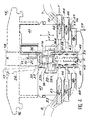
- FIG 3 is a schematic cross section of a connection assembly according to the invention.
- This connection assembly comprises a female connector 15 and a male connector 18.
- the female connector comprises a housing 16 provided with an inlet window 17 allowing the insertion of a male connector 18.
- This window 17 is located on one side front of the housing 16.
- the latter can be fixed by snap-fastening, on a support 22 shown in non-detailed manner in the figure.
- the support 22 can for example be fixed to a partition in a building.
- the female connector also includes, inside this housing and facing the window, a first group of connection terminals such as 28 and a second group of connection terminals such as 29, respectively connected, as will be seen more far in detail, at the corresponding ends of lines such as 32, 33 of the first and second successive sections 7, 8 of the network cable of FIG. 1.
- the male connector 18 is shown at 26 in its insertion position in the female connector.
- This male connector has connection terminals 21 which come into sliding contact with the corresponding connection terminals 28 of the female connector.
- connection terminals 21 make it possible to connect a terminal to the sections 7, 8 of the network, by a multiline connection cable 5 with ground shielding.
- the terminals 21 are of the "insulation piercing" type; they are in contact with each conductor 10 of the connection cable of the additional unit or apparatus, by virtue of the piercing of the insulating sheath 11 surrounding the conductor 10.
- the retractable movable means 35 give the connector, as will be seen in detail below, its universal character. They make it possible to ensure the continuity of the transmissions on the network, in particular between the stations or terminals connected to the sections 7, 8 of cable of this network, before the insertion of the male connector; they also make it possible to manage the connections of the lines of the connection cable 5 with the lines of the cable sections 7, 8 of the network, as well as the interconnections between the lines of the network cable sections, after insertion of the male connector into the female connector . Other lines of the network cable sections, and other contacts not referenced, are represented in FIG. 3.
- connection assembly further comprises a shield 23 of the connection terminals of the female connector.
- This shield forms a sheath at least partially enveloping a first and a second group of connection terminals 28, 29 of the female connector located opposite the window 17, inside the housing 15.
- the male connector 18 also includes a shield. external 24 which forms a sheath at least partially enveloping the connection terminals 21 of this connector.
- This sheath can for example be a metallized layer deposited on the insulating support 25 of the connection terminals 21.
- This support is moreover provided with an elastic lever 26 allowing the male connector to be held in position in the female connector, thanks to its snap-fastening on the front face of the housing 16.
- the metallized sheath 24 is brought into contact, by crimping, in a manner not shown in the figure, with the shielding 13, 14 (FIG. 2) of the connection cable 5.
- the shielding sheath 24 of the male connector comes into contact, during insertion, with the shielding sheath 23 of the female connector. Good electrical contact between these two sleeves is ensured, for example, by means of two elastic tabs such as 27 and 75, as will be seen more clearly with reference to the description of FIG. 6, produced in the sleeve 23 and based on the shield sheath 24 of the male connector, on either side of the latter.
- connection assembly also includes means which will be described later in relation to FIG. 5, to ensure electrical continuity between the shield 23 of the female connector and the shield of each section of the network.
- These means notably comprise connection terminals of the female connector, contacts connected to these terminals and respectively connected to conductive shielding lines of the cable sections 7, 8 of the network, and an electrical connection jumper belonging to retractable mobile means 35 internal to the female connector.
- Figure 4 is a more detailed schematic cross section of the connection assembly of the invention. This figure will allow better understand the structure of the retractable mobile means 35 which make it possible to ensure the continuity of the transmissions on the network before insertion of the male connector and the establishment of the connections between the network and the terminal connected to the male connector, during the insertion of that -this in the female connector. The same elements have the same references in this figure and in Figure 3.
- the terminals 28 of the first group of connection terminals of the female connector are connected respectively by first connection means, at the ends of lines, such as line 32, of the first section 7 of the network cable. These first connection means will be described later in detail.
- the terminals 29 of the second group of connection terminals of the female connector are respectively connected by second connection means which will be described later in detail, at the ends of lines, such as line 33, of the second section 8 of the network cable. .
- the terminals 28, 29 of the first and second groups are located respectively opposite each other.
- each cable section such as that which has been described in FIG. 2 has eight lines
- the first and second groups of terminals 28, 29 respectively comprise eight terminals. Only one terminal of each group is shown in this figure.
- the electrical connection means 35 mobile and retractable move by sliding between the first and second groups of terminals 28, 29, under the thrust of the male connector 18, during insertion.
- These retractable means comprise an insulating support 36 and a group of jumpers for electrical connections such as 37, 38, in the form of a U for example.
- Each rider has two branches of identical lengths. Before complete insertion of the male connector 18 into the female connector, the two branches 37A and 37B or 38A and 38B of each jumper such as 37 or 38 are respectively in contact with a terminal such as 28 of the first group and a terminal such as 29 of the second group, whatever the length L1 or L2 of the branches of the jumper considered, this length being measured parallel to the longitudinal axis X′X of the female connector.
- the branches of all the riders of the group can all have the same first length L1 (such as the jumper 37 in the figure), or all have the same second length L2 (such as the jumper 38) less than the first length L1. It is also possible that for the group of jumpers held by the insulating support 36, jumpers of a first set have branches having the first length L1 and jumpers of a second set have branches having the second length L2. This possibility of choosing the lengths of the branches of the jumpers gives the connection assembly its universal character.
- the terminals 21 of the male connector respectively come into sliding contact with the terminals 28 of the first group of the female connector, at the time of insertion of the male connector.
- the retractable movable means 35 are shown in this figure in the retracted position, the male connector 18 being inserted into the female connector. (These retractable means are in the so-called “free” or “not pressed in” position, when the male connector is not inserted). They are pushed by a spring 39 bearing on the bottom of a housing 40 made in two insulating support blocks 41, 47 whose structure will be described later in detail.
- the first connection means comprise a first group of line contacts such as the contact 43, passing through a first insulating support block 41 made integral with the housing 16 by means which are not shown in detail in the figure. These line contacts of the first group lead respectively to a first and a second face 44, 45 of this first support block.
- the second connection means comprise a second group of line contacts, such as the contact 46, which pass through the second insulating support block 47, which can be joined to the housing 16. These contacts 46 of the second group, respectively lead to first and second faces 48, 49 of the second support block 47.
- the contacts 43 of the first group are respectively connected on the side of the first face 44 of the first support block 41, at the ends of the lines, such as 32, of the first section of the network cable 7.
- the contacts 46 of the second group are respectively connected on the side of the first face 48 of the second support block 47, at the ends of lines such as 33 of the second section of cable 8 of the network.
- the contacts 43 of the first group are connected, on the side of the second face 45 of the first support block 41, to a first circuit 50.
- This first circuit is a printed circuit having tracks respectively connected to the connection terminals 28 of the first group and to the ends of the contacts 43 so as to ensure the electrical connection between the terminals 28 of the first group and the lines 32 of the first section 7 of the network cable.
- the contacts 46 of the second group are connected respectively, on the side of the first face 48 of the second support block 47, to the line ends 33 of the second cable section 8 of the network. These contacts are also connected, on the side of the second face 49 of the second support block 47, to a second circuit 51 which is a printed circuit having tracks respectively connected to the terminals 29 of connection of the second group. In this way the electrical connection is ensured between the connection terminals 29 of the second group 29 and the lines 33 of the second section of cable 8 of the network.
- the first faces 44, 48 of the first and second support blocks 41, 47 are located respectively opposite two internal lateral faces of the housing 16.
- the second faces 45, 49 of the first and second support blocks 41, 47 are located opposite one from the other.
- the housing 40 contains the two printed circuits and the two blocks can be assembled and positioned by means of positioning pins not referenced.
- Each line contact such as the contacts 43, 46 of the first and second groups, is a self-stripping contact with a cutting fork 55.
- the end of each line such as 32, of the first or second section is inserted into this fork which cuts the insulating sheath surrounding the conductor of this line; electrical contact is ensured by pinching the driver in the fork.
- insulating insertion pushers such as the pushbutton 56 which has an opening 57 having a dimension close to that of the insulating sheath of line 32
- the end of line 32 is introduced into this opening which is thus made integral with the pusher.
- the insertion of this pusher into a housing 58 surrounding the contact in the corresponding support block 41 or 47, on the side of the first face 44 or 48 of this support block, causes the insulating sheath to be cut by the cutting fork 55 , as well as the pinching of the conductor surrounded by it.
- the housings 58 of the pushers 56 extend towards the rear face of the housing 16, in the direction of the arrow 59, by gutters not shown in this figure; they respectively make it possible to contain the lines of the considered section of each cable, in the vicinity of their ends.
- Figure 5 shows schematically and in cross section a partial view of the female connector in the vicinity of the shielding sleeve 23.
- the same elements have the same references in this figure and in the previous figures.
- the means which make it possible to ensure electrical continuity between the shield 23 of the female connector and the shield of each section of the network comprise in each of the two support blocks 41, 47, an additional contact and push button, of structure and arrangement identical to those of each push button and line contact described above.
- FIG. 5 This figure does not show the additional pushers which are identical to the pushers 56 of the previous figure.
- Contacts additional are shown at 60, 61 in FIG. 5.
- Each contact is connected on the side of the first face of the support block which corresponds to it to a screen line in contact with the screen of the corresponding section of cable of the network.
- the additional contact 60 is connected to a line 62 of the first section 7 of the network (FIG. 4). This line in fact corresponds to line 13 in FIG. 2.
- the additional contact 61 of the second support block 47 is connected to a screen line 63 in contact with the screen of the second section of cable 8 of the network. (figure 2).
- Each additional contact is connected on the side of the second face 45 or 49 of the support block 41 or 47 which corresponds to it, to an additional track of the corresponding printed circuit.
- the additional contact 60 is connected, on the side of the second face 45 of the first support block 41, to an additional track 65 of the first printed circuit 50.
- the additional contact 61 is connected, on the side of the second face 49 of the second block 47, to an additional track 66 of the second printed circuit 51.
- the additional track 65 of the first printed circuit 50 is connected to the shielding sheath 23 of the female connector, for example by a metal tongue 67 having a fork at its end 68; this fork clamps the additional track 65, so as to ensure electrical continuity between the shielding line 62 of the first network section 7 and the shielding sheath 23, via the additional contact 60.
- the additional track 66 connected to the shielding line 63 of the second section 8 of the network cable is here connected to the shielding sheath 23 of the female connector by an assembly which comprises: a additional terminal 70 of the second group of connection terminals of the female connector, an additional connection jumper 71 of the retractable mobile means 35, and an additional terminal 72 of the first group of connection terminals of the female connector, connected to the additional track 65 of the first printed circuit 50.
- the additional jumper 71 is in permanent contact, before and after insertion, with the additional terminals 70 and 72, whether the male connector is inserted or not in the female connector.
- Shielding continuity is thus permanently ensured between the shielding of the female connector and the shields of the network cable sections when the male connector is inserted into the female connector, the outer shielding 24 (FIG. 3) of this connector comes into contact with the shield 23 of the female connector; the retractable means 35 are pushed by the male connector and ensure, thanks to the additional jumper 71, the electrical continuity between the shield 24 of the male connector, the shield 23 of the female connector, and the shield lines 62, 63 of the sections network cable.
- the additional jumper 71 has a shape identical to that of the connecting jumpers 37 in FIG. 4.
- the continuity of the shielding between the shielding sheath 23 and the shielding lines 62, 63 of the network cables, could be ensured without using additional connection terminals and additional jumper; it would be possible, for example, to implement a second tongue of the sheath 23, comparable to the tongue 67, and having a fork in contact with the additional track 66 of the second printed circuit 50. It would also be possible to ensure the continuity of the shields thanks to connection wires connecting the sheath 23 to each of the additional tracks 65, 66 of the first and second printed circuits 50, 51.
- FIG. 6 is a schematic longitudinal section which represents the interior of the female connector, in a plane close to the second face 45 of the first support block 41 and mobile means 35.
- the same elements have the same references in this figure and on the previous figures. It is assumed that the male connector 18 is not completely inserted into the female connector. We can see in this figure the shielding sheath 23 of the female connector, the first group of connection terminals 28 and the contact tabs 27, 75. The mobile means have also been shown in their two positions, retracted A or free B 35. A distinction is also made in this figure, for example a first set of link jumpers 37 having the first length L1, a second set of link jumpers 38 having the second length L2, less than the first length.
- connection between the ends of terminals 28 of the first group and connection pads 73 of the first printed circuit 50 We also distinguish the connection between the ends of terminals 28 of the first group and connection pads 73 of the first printed circuit 50.
- additional track 65 of the first printed circuit 50 in contact with the tongue 67 which electrically connects this track additional with the shielding sheath 23.
- the connecting tracks 74 of the printed circuit Partially shown are the connecting tracks 74 of the printed circuit, which make it possible to connect the terminals 28 of the first group with the contacts 43 which ensure the connection with the lines of the first section of cable 7.
- the additional track 65 is connected to the additional terminal 72 of the first group; there is also shown the additional jumper 71 ensuring electrical continuity between the additional terminal 72 of the first group and the additional terminal 70 of the second group ( Figure 5).
- connection assembly of the invention also comprises in the window 17, which allows the insertion of the male connector, polarizing means whose role will be better understood with the aid of FIGS. 7 and 8.
- the window 17 is shown face on these two figures while the male connector is shown very schematically at 18. The same elements have the same references in these figures and in the previous figures.
- the male connector is a connector intended for the connection of a telephone terminal for example, on a telephone network.
- the connector is intended for the connection of a data processing terminal on a computer network.
- the cross section of the male connector has a keying boss 80, flowing in a corresponding slide 81 of the window 17, while in Figure 7 the cross section of the male connector does not have this keying boss .
- a keying means constituted for example by an elastic jumper 82 is therefore introduced into the slide 81 shown in FIG.
- window 17 includes a retractable shutter at the time of insertion of the male connector.
- This retractable shutter can be constituted by a sliding shutter 83, pushed by a spring 84, integral with the housing 16. This spring makes it possible to close the window 17 using the shutter 83, in the absence of a male connector and can open this window when a male connector is to be inserted into the female connector.
- connection assembly of the invention makes possible, which depend on the lengths of the connection jumpers used in the retractable mobile means 35, will be better understood with the aid of FIGS. 9A, 9B, ... , 11B, 11C. These various figures make it possible in particular to show the universal appearance of this connection assembly. The same elements have the same references in these figures and in the previous figures.
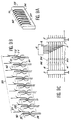
- FIG. 9A shows schematically and in perspective, a first embodiment of the retractable mobile means 35 of FIG. 4.
- the insulating support 36 carries a group 90 of identical jumpers 37, identical.
- Each rider has the shape of a U whose two branches have the same first length L1; there is also shown an additional jumper 71 which ensures, as indicated above, the continuity of the mass shields and whose branches also have the first length L1.
- FIG. 9B shows schematically and in perspective, the group 90 of jumpers 37 in FIG. 9A, the first group 91 of connection terminals 28 and the second group 92 of connection terminals 29 of the female connector.
- the additional terminal 72 of the first group and the additional terminal 70 of the second group; these additional terminals ensure, by contact with the additional jumper 71, the electrical continuity of the earth shields.
- the jumpers 37 of the group 90, as well as the additional jumper 71 are shown in solid lines when the support 36 is in the free position (that is to say not pressed into the female connector, before insertion of the male connector). These jumpers are shown in broken lines when the support 36 is in the retracted position (that is to say pressed into the female connector, after insertion of the male connector).
- connection terminals 21 of the male connector has also been shown diagrammatically, which when inserted, are respectively in contact with the corresponding terminals 28 of the first group of the female connector.
- the terminals 28 of the first group 90, and all the corresponding terminals 29 respectively of the second group 91 are in permanent electrical connection, whatever the free or retracted position of the support 36, the first length of the connecting jumpers being chosen accordingly. It is the same for the additional terminals 70 and 72 which ensure the continuity of the ground shields, by permanent contact with the additional jumper 72.
- the connections obtained in this embodiment are shown diagrammatically in FIG. 9C.
- the connection assembly 4 is represented schematically by a group 96 of switches 94 connected respectively to the cable sections 7, 8 of the network.
- the additional switch 95 is connected to the shielding lines of each section.
- the stations 2 and 3 of the network have also been represented, as well as the terminal 6 connected to the network by the multiline cable. 5, also comprising a ground shielding line.
- the insertion of the male connector does not cause any break in the connections between the lines of sections 7, 8 of the network.
- the switches 94 of the group 96 are therefore all in the closed position and schematically represent the continuity of the electrical connections respectively between the terminals 28 of the first group 91 and the terminals 29 of the second group 92; the continuity of the earth shields is represented by the closed position of the switch 95.
- connection cable 5 and the additional screen line of this cable are respectively connected, to the transmission lines and to the screen line of each cable section. There is no break in the links on the network.
- FIG. 10A shows schematically and in perspective, a second embodiment of the retractable mobile means 35 of FIG. 4.
- the insulating support 36 carries a group 90 of link jumpers 37, which are identical.
- Each jumper has the shape of a U, the two branches of which have the same second length L2, less than the first length L1 of the jumpers of FIG. 9A.
- the additional jumper 71 which ensures, as indicated above, the continuity of the ground shields.
- the branches of this additional jumper are of first length L1, greater than the second length L2.
- FIG. 10B shows schematically and in perspective, the group 90 of jumpers 38 of FIG. 10A, the first group 91 of connection terminals 28, the second group 92 of connection terminals 29 of the female connector.
- the additional terminal 72 of the first group and the additional terminal 70 of the second group of terminals which ensure, by contact with the additional jumper 71, the electrical continuity of the earth shields.
- the jumpers 38 of the group 90, as well as the additional jumper 71 are shown in solid lines when the support 36 is in the free position (that is to say not pressed into the female connector, before insertion of the male connector). These jumpers are shown in broken lines when the support 36 is in the retracted position (that is to say pressed into the female connector, after insertion of the male connector).
- connection terminals 21 of the male connector has also been shown diagrammatically, which when inserted, are respectively in contact with the corresponding terminals 28 of the first group of the female connector.
- the terminals 28 of the first group 90, and all the corresponding terminals 29 respectively of the second group 91 are in permanent electrical connection, the support 36 not being pressed into the female connector . It is the same for the additional terminals 70 and 72 which ensure the continuity of the ground shields, by permanent contact with the additional jumper 72 whose branches are of first length (length of the branches of the jumpers of FIG. 9A). After insertion, due to the shorter length L2 of the jumpers 38, there is a break in all the links in the network, with the exception of the ground shielding link.
- Connection assembly 4 is shown schematically by a group 96 of switches 94 respectively connected to the cable sections 7, 8 of the network.
- the additional switch 95 is connected to the shielding lines of each section.
- the switches 94 of group 96 are therefore all in the open position and schematically represent the interruption of the electrical connections, respectively between the terminals 28 of the first group 91 and the terminals 29 of the second group 92; the continuity of the earth shields is represented by the closed position of the switch 95.
- connection cable 5 on insertion, the transmission lines of the connection cable 5 are respectively connected to the lines of the cable section 7.
- the electrical shielding continuity is ensured between the cable sections 7, 8, and the cable 5.
- the terminal 6 is therefore connected to all the lines of the cable section 7 of the network and can communicate with the station 2, while the communication is interrupted on the network, between the stations 2 and 3.
- FIG. 11A shows schematically and in perspective, a third embodiment of the retractable mobile means 35 of FIG. 4.
- the insulating support 36 carries a group 90 of connecting jumpers which comprises a first set of jumpers 37 having branches of first length L1 (length of the branches of the jumpers of FIG. 9A), and a second set of jumpers 38 having branches of second length L2 (length of the branches of the jumpers of FIG. 10A).
- FIG. 11B schematically and in perspective represents the group 90 comprising a set of jumpers 37 of first length L1 and a set of jumpers 38 of second length L2, the first group 91 of connection terminals 28 and the second group 92 of connection terminals 29 of the female connector. Also shown in this figure is the additional terminal 72 of the first group and the additional terminal 70 of the second group of terminals which ensure, by contact with the additional jumper 71, the electrical continuity of the ground shields.
- jumpers 37 and 38 of each set of the group of jumpers 90, as well as the additional jumper 71 are shown in solid lines when the support 36 is in the free position (that is to say not pressed into the female connector, before insertion male connector). These jumpers are shown in broken lines when the support 36 is in the retracted position (that is to say pressed into the female connector, after insertion of the male connector).
- connection terminals 21 of the male connector has also been shown diagrammatically, which when inserted, are respectively in contact with the corresponding terminals 28 of the first group of the female connector.
- the terminals 28 of the first group 90, and all the corresponding terminals 29 of the second group 91 respectively are in permanent electrical connection. It is the same for the additional terminals 70 and 72 which ensure the continuity of the earth shields, by permanent contact with the additional jumper 72.
- the connections are interrupted on the lines of the network which are connected to the connection terminals of the female connector which respectively correspond to the jumpers 38 of the second set.
- the links are maintained on the lines of the network connected to the connection terminals of the female connector, which respectively correspond to the jumpers 37 of the first set.
- connection assembly 4 is represented diagrammatically by a group 96 of switches connected respectively to the cable sections 7, 8 of the network.
- the additional switch 95 is connected to the shielding lines of each section.
- the insertion of the male connector cuts the connections between the lines of the sections 7, 8 of the network which correspond respectively to the jumpers 38, which is shown diagrammatically in the figure by a set of open switches 98.
- connections are on the contrary maintained on the lines of the network which respectively correspond to the jumpers 37, which is shown diagrammatically on the figure by a set of closed switches 99.
- the continuity of the ground shields is represented by the closed position of the switch 95 .
- terminal 6 is connected to all lines of section 7, and partially connected to lines of section 8.
- the support 36 includes notches and openings not referenced, making it possible to maintain the jumpers on this support.
- connection assembly which has just been described does indeed have a universality character since it allows all the possible combinations of connections of a terminal on a network, while providing the possibility of obtaining continuity of the ground shields. .
Landscapes
- Details Of Connecting Devices For Male And Female Coupling (AREA)
- Coupling Device And Connection With Printed Circuit (AREA)
- Computer And Data Communications (AREA)
- Shielding Devices Or Components To Electric Or Magnetic Fields (AREA)
Claims (16)
- Mehrzweckverbindungseinrichtung um ein Verarbeitungsterminal über ein mehradriges Kabel an ein Datenübertragungsnetz anzuschließen, enthaltend:- eine Steckbuchse (15) die ein Gehäuse (16) enthält, das auf der Vorderseite dieses Gehäuses ein Eingangsfenster (17) aufweist, Verbindungskontaktelemente (28, 29), jeweils verbunden mit den Enden (32, 33) von Übertragungsleitungen eines ersten und, anschließend, eines zweiten Teilstücks (7, 8) von Netzwerkkabeln;- ein Stecker (18), der Verbindungskontaktelemente (21) enthält, die jeweils verbunden sind mit den Leitungen eines mehradrigen Verbindungskabels (5) des genannten Terminals (6), wobei die jeweiligen Verbindungskontaktelemente (21) des Steckers durch Hineingleiten in Kontakt kommen mit den entsprechenden Kontaktelementen (28) der Steckbuchse während des Einführens des Steckers in das genannte Fenster, um das Terminal an das Netz anzuschließen;- eine erste Gruppe von Kontaktelementen (28) der Steckbuchse jeweils verbunden durch erste Verbindungsmittel (43, 50) mit den entsprechenden Enden der Adern des Kabels des ersten Teilstücks (7), die jeweils in Kontakt kommen mit den Verbindungskontaktelementen (21) des Steckers während des genannten Einführens;- eine zweite Gruppe von Kontaktelementen (29) der Steckbuchse, jeweils verbunden durch zweite Verbindungsmittel (46, 51) mit den entsprechenden Enden der Adern des Kabels des zweiten Teilstücks (8) ;- und elektrische Verbindungsmittel (35), beweglich und verschiebbar während des Einführens des Steckers, innerhalb der Steckbuchse und sich zwischen den Kontaktelementen (28, 29) der ersten und der zweiten Gruppe der Steckbuchse bewegend, um die Kontinuität der Kommunikationen im Netz vor dem genannten Einführen zu gewährleisten und um den Anschluß des Terminals ans Netz zu gewährleisten, nach dem Einführen.
- Mehrzweckverbindungseinrichtung nach Anspruch 1, dadurch gekennzeichnet, daß die beweglichen Mittel der elektrischen Verbindungen (35) einen beweglichen Träger (36) enthalten, der vom Stecker (18) während dem Einführen verschoben wird, und eine Gruppe (90) von Reitern für elektrische Verbindungen, wobei jeder Reiter zwei Schenkel aufweist, jeweils in Kontakt mit einem Kontaktelement (28) der ersten Gruppe und mit einem entsprechenden Kontaktelement (29) der zweiten Gruppe der Steckbuchse, vor dem Einführen, wobei alle oder ein Teil der Reiter der genannten Gruppe Schenkel (37A, 37B - 38A, 38B) einer ersten und/oder einer zweiten Länge (L1, L2) haben.
- Mehrzweckverbindungseinrichtung nach Anspruch 2, dadurch gekennzeichnet, daß die Reiter (37) alle Schenkel (37A, 37B) der ersten Länge (L1) haben, um die Kontinuität der elektrischen Verbindung nach dem Einführen zu gewährleisten zwischen den Kontaktelementen (28) der ersten Gruppe der Steckbuchse und den jeweils entsprechenden Kontaktelementen (29) der zweiten Gruppe der Steckbuchse.
- Mehrzweckverbindungseinrichtung nach Anspruch 2, dadurch gekennzeichnet, daß die Reiter (38) alle Schenkel (38A, 38B) der zweiten Länge (L2) haben, damit, nach dem Einführen, die elektrischen Verbindungen unterbrochen sind zwischen den Kontaktelementen (28) der ersten Gruppe der Steckbuchse und den jeweils entsprechenden Kontaktelementen (29) der zweiten Gruppe der Steckbuchse.
- Mehrzweckverbindungseinrichtung nach Anspruch 2, dadurch gekennzeichnet, daß die Reiter (37) der ersten Einheit Schenkel (37A, 37B) der ersten Länge (L1) haben und die Reiter (38) der zweiten Gruppe Schenkel (38A, 38B) der zweiten Länge (L2) haben, um nach dem Einführen die Kontinuität der elektrischen Verbindungen zwischen den Kontaktelementen einer ersten Einheit von Kontaktelementen (28, 29) der ersten und zweiten Gruppe der Steckbuchse zu gewährleisten, und um die jeweiligen elektrischen Verbindungen zu unterbrechen zwischen den Kontaktelementen einer zweiten Kontaktelementeeinheit (28, 29) der ersten und zweiten Gruppe der Steckbuchse.
- Mehrzweckverbindungseinrichtung nach Anspruch 2, dadurch gekennzeichnet, daß sie enthält:- eine Abschirmung (23) der Verbindungskontaktelemente (28, 29) der Steckbuchse, die eine Umhüllung bildet, die zumindest teilweise die Verbindungskontaktelemente der Steckbuchse im Innern des genannten Gehäuses umgibt und Mittel (61, 62, 65, 67, 70, 71, 72, 66) um die elektrische Kontinuität der Abschirmung der Steckbuchse mit den jeweiligen Abschirmungsadern (62, 63) des ersten und zweiten Kabelteilstücks des Netzkabels zu gewährleisten.- eine äußere Abschirmung (24) am Stecker, die eine weitere Umhüllung bildet, die teilweise die Kontaktelemente (21) des Steckers umgeben, wobei diese Umhüllung in Kontakt ist mit einer Abschirmungsader des genannten Verbindungskabels (5) des Terminals (6) und in Kontakt kommt mit der Abschirmung (23) der Steckbuchse während des Einfügens.
- Mehrzweckverbindungseinrichtung nach irgendeinem der Ansprüche 2 bis 6, dadurch gekennzeichnet, daß die ersten und zweiten Verbindungsmittel jeweils eine erste und eine zweite Gruppe (43, 46) von Leitungskontakten enthalten, die jeweils einen ersten und einen zweiten isolierenden, ins Gehäuse einsetzbaren Trägerblock durchqueren, wobei diese Kontakte jeweils an einer ersten und einer zweiten Seite (44, 45, oder 48, 49) jedes Trägerblocks austreten, wobei die Leitungskontakte (43, 46) der ersten und zweiten Gruppe jeweils verbunden sind, auf der ersten Seite (44, 48) von jedem Trägerblock (41 oder 47) mit den Enden der Leitungen (32, 33) des ersten und zweiten Teilstücks (7, 8) des Netzes, und auf der zweiten Seite (45 oder 49) jedes Trägerblocks jeweils verbunden sind mit einem ersten und einem zweiten Schaltkreis (50, 51), der jeweils die Kontaktelemente (28) der ersten Gruppe mit den Leitungskontakten (43) der ersten Gruppe, und die Kontaktelemente (29) der zweiten Gruppe mit den Leitungskontakten (46) der zweiten Gruppe verbindet.
- Mehrzweckverbindungseinrichtung nach Anspruch 7, dadurch gekennzeichnet, daß die ersten Seiten (44, 48) des ersten und zweiten Trägerblocks (41, 47) jeweils den beiden inneren Seitenflächen des Gehäuses (16) gegenüberliegen und die zweiten Seiten (45, 49) des ersten und zweiten Trägerblocks sich einander gegenüberliegen, wobei der erste und der zweite Schaltkreis (50, 51) gedruckte Schaltkreise sind, deren Leiterbahnen jeweils verbunden sind mit den Kontaktelementen (28, 29) der ersten und zweiten Kontaktelementengruppe der Steckbuchse.
- Mehrzweckverbindungseinrichtung nach Anspruch 4, dadurch gekennzeichnet, daß jeder Leitungskontakt (43, 46) der ersten und zweiten Gruppe ein selbstabisolierender Gabelkontakt (55) ist, in den das Ende der entsprechenden Ader des Teilstücks des Netzkabels eingeführt wird, wobei jede Ader ein Leiter (10) ist, der von einer isolierenden Hülle (11) umgeben ist, wobei das Einführen der Ader in den Leitungskontakt das Durchschneiden der isolierenden Hülle und das Klemmen des Leiters durch die Gabel bewirkt.
- Mehrzweckverbindungseinrichtung nach Anspruch 9, dadurch gekennzeichnet, daß jeder Leitungskontakt (43 oder 46) versehen ist mit einem isolierten Drücker (56) für das Einführen der entsprechenden Leitungsenden des Netzkabelteilstücks, wobei dieser Drücker fest verbunden ist mit dem genannten Leitungsende und eingedrückt wird in einen Sitz (58), der den Leitungskontakt im Trägerblock umgibt, an der ersten Seite (44 oder 48) von diesem Trägerblock um das Durchschneiden der genannten Hülle und die Klemmung des genannten Leiters am Ende der Ader zu bewirken, wobei jeder Trägerblock an der ersten Seite (44 oder 48) Kabelführungen enthält für die Unterbringung der Leitungen des entsprechenden Kabelteilstücks, in der Nähe der Enden dieser Leitungen , wobei diese Kabelführungen nach einer Rückwand des Gehäuses (16) ausgerichtet sind.
- Mehrzweckverbindungseinrichtung nach Anspruch 10, dadurch gekennzeichnet, daß die Mittel zur Gewährleistung der elektrischen Kontinuität zwischen der Abschirmung der Steckbuchse und der Abschirmungsader jedes Netzkabelteilstücks in jedem der Trägerblöcke (41, 47) einen Kontakt (60 oder 61) enthält und einen zusätzlichen isolierenden Drücker, der in Struktur und Anordnung identisch ist mit jedem Drücker (56) und Leitungskontakt (43), wobei dieser Kontakt an der ersten Seite des entsprechenden Trägerblocks verbunden ist mit der Abschirmungsader (62 oder 63) des entsprechenden Netzteilstücks (7 oder 8), und an der zweiten Seite (45 oder 49) mit einer zusätzlichen Leiterbahn (65 oder 66) der entsprechenden gedruckten Schaltung (50 oder 51), wobei diese zusätzliche Leiterbahn verbunden ist mit der Abschirmung (23) der Steckbuchse.
- Mehrzweckverbindungseinrichtung nach Anspruch 11, dadurch gekennzeichnet, daß die zusätzliche Leiterbahn (65) der ersten gedruckten Schaltung (50) verbunden ist mit der Abschirmung (23) der Steckbuchse durch direkten Kontakt mit dieser Abschirmung, wobei die zusätzliche Leiterbahn (66) der zweiten gedruckten Schaltung (51) verbunden ist mit der Abschirmung (23) der Steckbuchse durch ein zusätzliches Kontaktelement (72) der ersten Gruppe, verbunden mit der zusätzlichen Leiterbahn (65) der ersten gedruckten Schaltung durch ein zusätzliches Kontaktelement (70) der zweiten Gruppe, verbunden mit der zusätzlichen Leiterbahn (66) der zweiten gedruckten Schaltung (51), und durch einen zusätzlichen Verbindungsreiter (71) der verschiebbaren Verbindungsmittel (35), wobei dieser zusätzliche Reiter Kontakt hat mit den zusätzlichen Kontaktelementen (70, 72) der ersten und der zweiten Gruppe, vor und nach dem Einführen des Steckers (18) .
- Mehrzweckverbindungseinrichtung nach irgendeinem der Ansprüche 1 bis 6, dadurch gekennzeichnet, daß das genannte Fenster (17) Unverwechselbarkeitsmittel (81, 82) aufweist, die den Anschluß eines Informatikterminals an ein Telefondaten-Übertragungsnetz nicht zulassen.
- Mehrzweckverbindungseinrichtung nach irgendeinem der Ansprüche 1 bis 6 und 13, dadurch gekennzeichnet, daß das genannte Fenster (17) einen Verschluß (83) enthält, der zurückziehbar ist beim Einführen des Steckers (18) .
- Datenübertragungsnetz, dadurch gekennzeichnet, daß es zumindest eine Verbindungseinheit enthält, die irgendeinem der Ansprüche 1 bis 14 entspricht.
- Mehrzweckverbindungseinrichtung um ein Verarbeitungsterminal an ein mehradriges Datenübertragungsnetz anzuschließen, enthaltend:- eine Steckbuchse (15), bestehend aus einem Gehäuse (16) versehen mit einem Eingangsfenster (17) auf einer vorderen Seite dieses Gehäuses und, im Innern dieses Gehäuses und dem Fenster gegenüber, Kontaktelemente (28, 29) jeweils verbunden mit den entsprechenden Enden (32, 33) der Übertragungsleitungen von zumindest einem Teilstück (7) des Netzkabels;- einen Stecker (18) mit Kontaktelementen (21), jeweils verbunden mit den Leitungen eines mehradrigen Verbindungskabels (5) des genannten Terminals (6) , wobei die Kontaktelemente (21) jeweils durch Hineingleiten in Kontakt kommen mit den entsprechenden Kontaktelementen (28) der Steckbuchse, während des Einführens des Steckers in das genannte Fenster, um das Terminal an das Netz anzuschließen;- mindestens eine Gruppe von Verbindungskontaktelementen der Steckbuchse, jeweils durch Verbindungsmittel (43, 50) verbunden mit den entsprechenden Enden der Adern des Netzkabels (7) und jeweils in Kontakt tretend mit den Kontaktelementen (21) des Steckers während des genannten Einführens;- elektrische Verbindungsmittel (35) , innerhalb der Steckbuchse, um die Kontinuität der Verbindungen im Netz nach dem genannten Einführen aufrechtzuerhalten;- eine Abschirmung (23) der Verbindungskontaktelemente (28, 29) der Steckbuchse, die eine Umhüllung bildet, die zumindest teilweise die Verbindungskontaktelemente innerhalb des genannten Gehäuses umgibt, und Mittel (61, 62, 65, 67, 70, 71, 72, 66) um die elektrische Kontinuität der Abschirmung der Steckbuchse mit den Abschirmleitungen (62) des Netzkabels zu gewährleisten;- eine Abschirmung (24) außerhalb des Steckers, die eine weitere Umhüllung bildet, die zumindest teilweise die Kontaktelemente (21) des Steckers umgibt, wobei diese Umhüllung Kontakt hat mit einer Abschirmleitung des genannten Verbindungskabels (5) des Terminals (6) und in Kontakt kommt mit der Abschirmung (23) der Steckbuchse, während des Einführens.
Applications Claiming Priority (2)
| Application Number | Priority Date | Filing Date | Title |
|---|---|---|---|
| FR8814043 | 1988-10-27 | ||
| FR8814043A FR2638576B1 (fr) | 1988-10-27 | 1988-10-27 | Ensemble universel de connexion, pour raccorder un terminal de traitement a un reseau de transmission de donnees |
Publications (2)
| Publication Number | Publication Date |
|---|---|
| EP0366556A1 EP0366556A1 (de) | 1990-05-02 |
| EP0366556B1 true EP0366556B1 (de) | 1993-03-17 |
Family
ID=9371330
Family Applications (1)
| Application Number | Title | Priority Date | Filing Date |
|---|---|---|---|
| EP19890402961 Expired - Lifetime EP0366556B1 (de) | 1988-10-27 | 1989-10-26 | Mehrzweckverbindungseinrichtung, um eine Datenverarbeitungsendstation an ein Übertragungsnetz anzuschliessen |
Country Status (10)
| Country | Link |
|---|---|
| US (1) | US4969836A (de) |
| EP (1) | EP0366556B1 (de) |
| JP (1) | JPH02210777A (de) |
| KR (1) | KR900007133A (de) |
| CN (1) | CN1022721C (de) |
| AU (1) | AU626328B2 (de) |
| CA (1) | CA2001601A1 (de) |
| DE (1) | DE68905434T2 (de) |
| ES (1) | ES2040486T3 (de) |
| FR (1) | FR2638576B1 (de) |
Families Citing this family (19)
| Publication number | Priority date | Publication date | Assignee | Title |
|---|---|---|---|---|
| FR2664754B1 (fr) * | 1990-07-11 | 1992-10-16 | Interconnection Inf | Connecteur male pour reseau de communication informatique et/ou telephonique. |
| US5035635A (en) * | 1990-09-04 | 1991-07-30 | Tsai Shiang Shiun | Revolving safety socket |
| GB2255694A (en) * | 1991-05-10 | 1992-11-11 | British Telecomm | Convertible line jack unit |
| GB2264843B (en) * | 1992-02-28 | 1995-09-20 | Texas Instruments Ltd | An interface device for coupling a host device having a network interface to a computer network having a predetermined communications medium |
| JP2842063B2 (ja) * | 1992-07-30 | 1998-12-24 | 株式会社村田製作所 | モジュラーコネクタ |
| FR2694456B1 (fr) * | 1992-07-31 | 1994-09-09 | Pouyet Int | Prise femelle de type "modular jack" et à connectique intégrée. |
| FR2701605B1 (fr) * | 1993-02-10 | 1995-03-31 | Interconnection Inf | Connecteur mâle déconnectable pour réseau de communication. |
| FR2708821A1 (fr) * | 1993-07-30 | 1995-02-10 | Amp France | Boîte d'interface d'abonné. |
| DE4403730A1 (de) * | 1994-02-07 | 1995-08-10 | Daetwyler System Und Netzwerk | Vorrichtung zur Verbindung von Datennetzverkabelungen |
| US5619684A (en) * | 1994-07-25 | 1997-04-08 | International Business Machines Corporation | Method and apparatus for consistent user interface in a multiple application personal communications device |
| US5568536A (en) * | 1994-07-25 | 1996-10-22 | International Business Machines Corporation | Selective reconfiguration method and apparatus in a multiple application personal communications device |
| US5590373A (en) * | 1994-07-25 | 1996-12-31 | International Business Machines Corporation | Field programming apparatus and method for updating programs in a personal communications device |
| JPH11195468A (ja) * | 1998-01-06 | 1999-07-21 | Sumitomo Wiring Syst Ltd | ストレート/クロス切替ジャック |
| US6350156B1 (en) | 2000-04-24 | 2002-02-26 | Tyco Electronics Corporation | Modular jack with deflectable plug-blocking member |
| US6612856B1 (en) * | 2001-12-17 | 2003-09-02 | 3Com Corporation | Apparatus and methods for preventing cable-discharge damage to electronic equipment |
| EP1685630A2 (de) * | 2003-11-18 | 2006-08-02 | Tyco Electronics AMP GmbH | Verbindersockel |
| CN100539323C (zh) * | 2004-06-10 | 2009-09-09 | 北卡罗来纳科姆斯科普公司 | 插座组件和用于制作该插座组件的方法 |
| US7033219B2 (en) * | 2004-06-10 | 2006-04-25 | Commscope Solutions Properties, Llc | Modular plug assemblies, terminated cable assemblies and methods for forming the same |
| US7083472B2 (en) * | 2004-06-10 | 2006-08-01 | Commscope Solutions Properties, Llc | Shielded jack assemblies and methods for forming a cable termination |
Family Cites Families (6)
| Publication number | Priority date | Publication date | Assignee | Title |
|---|---|---|---|---|
| CA1021421A (en) * | 1973-05-25 | 1977-11-22 | Leroy W. Fairbairn | Electrical connector for tape type electrical cables |
| JPH0785429B2 (ja) * | 1987-04-15 | 1995-09-13 | 松下電工株式会社 | テレホンモジユラ−ジヤツク |
| US4767357A (en) * | 1987-06-10 | 1988-08-30 | E. I. Du Pont De Nemours And Company | Daisy chain connector |
| US4772215A (en) * | 1987-10-15 | 1988-09-20 | Hubbell Incorporated | Electrical connector with enclosed internal switch |
| US4790767A (en) * | 1987-11-16 | 1988-12-13 | Prestolite Wire Corporation | Electrical connector for a distributorless ignition system |
| DK456788A (da) * | 1987-12-03 | 1989-06-04 | Evaristo Garcia Ramos | Datamatkoblingsorgan med automatisk sloejfelukning |
-
1988
- 1988-10-27 FR FR8814043A patent/FR2638576B1/fr not_active Expired - Lifetime
-
1989
- 1989-10-17 AU AU42988/89A patent/AU626328B2/en not_active Ceased
- 1989-10-26 CA CA002001601A patent/CA2001601A1/en not_active Abandoned
- 1989-10-26 ES ES198989402961T patent/ES2040486T3/es not_active Expired - Lifetime
- 1989-10-26 US US07/426,753 patent/US4969836A/en not_active Expired - Fee Related
- 1989-10-26 EP EP19890402961 patent/EP0366556B1/de not_active Expired - Lifetime
- 1989-10-26 DE DE8989402961T patent/DE68905434T2/de not_active Expired - Fee Related
- 1989-10-26 CN CN89108941A patent/CN1022721C/zh not_active Expired - Fee Related
- 1989-10-27 KR KR1019890015605A patent/KR900007133A/ko not_active Application Discontinuation
- 1989-10-27 JP JP1281606A patent/JPH02210777A/ja active Pending
Also Published As
| Publication number | Publication date |
|---|---|
| ES2040486T3 (es) | 1993-10-16 |
| CA2001601A1 (en) | 1990-04-27 |
| EP0366556A1 (de) | 1990-05-02 |
| FR2638576B1 (fr) | 1990-12-14 |
| AU626328B2 (en) | 1992-07-30 |
| JPH02210777A (ja) | 1990-08-22 |
| AU4298889A (en) | 1990-05-31 |
| KR900007133A (ko) | 1990-05-09 |
| CN1042453A (zh) | 1990-05-23 |
| US4969836A (en) | 1990-11-13 |
| DE68905434T2 (de) | 1993-09-02 |
| FR2638576A1 (fr) | 1990-05-04 |
| CN1022721C (zh) | 1993-11-10 |
| DE68905434D1 (de) | 1993-04-22 |
Similar Documents
| Publication | Publication Date | Title |
|---|---|---|
| EP0366556B1 (de) | Mehrzweckverbindungseinrichtung, um eine Datenverarbeitungsendstation an ein Übertragungsnetz anzuschliessen | |
| EP0585179B1 (de) | Steckdose von Typ "Modular Jack" mit integrierten Anschlüssen | |
| FR2689987A1 (fr) | Système de connexion, en tant qu'interface, pour la connexion directe de supports d'informations, tels que des cartes de communication, à des moyens de communication. | |
| EP0635167B1 (de) | Trennbarer steckverbinder für kommunikationsnetz | |
| EP0911907B1 (de) | Verbindungsmodul für zwei einpaarige Leitungen | |
| WO2007122350A1 (fr) | Connecteur pour liaison a haut debit | |
| EP1271713B1 (de) | Schwachstrom-Modular Jackverbinder | |
| EP0474184B1 (de) | Verbinder für geschirmtes Zweileiterkabel mit Erdungsdrain | |
| EP1081808A1 (de) | Verbindungsvorrichtung für ein Mehrpaarkabel mit reduziertem Übersprechen zwischen den Paaren | |
| FR2517476A1 (fr) | Systeme de raccordement electrique et element de connecteur | |
| FR2566967A1 (fr) | Borne pour connexion de conducteur electrique par ressort de pressage | |
| WO1996019020A1 (fr) | Dispositif de derivation pour un cable blinde | |
| EP0537444B1 (de) | Vorrichtung zum Verbinden eines Übertragungsnetzes mit einer Vielzahl von Teilnehmern | |
| FR2562337A1 (fr) | Dispositif de connexion-deconnexion | |
| EP4270700A1 (de) | Verbindungsgehäuse für einpaar-ethernet-kabel und zugehörige verdrahtete ethernet-netzwerke | |
| EP1311024B1 (de) | Kamm und Verfahren zur Abzweigung für eine bestehende Leitung | |
| EP0157060A1 (de) | Selbstabisolierende Verbindungsvorrichtung für elektrische Leiter | |
| EP0902501B1 (de) | Anschlussmodul für Fernmeldekabel und Anschlusselement mit einem solchen Anschlussmodul | |
| FR2553940A1 (fr) | Dispositif pour la connexion electrique de conducteurs metalliques non denudes | |
| FR2692408A1 (fr) | Connecteur mâle pour réseau de communication informatique et/ou téléphonique. | |
| FR2714219A1 (fr) | Bornier pour connecteur de distribution et connecteur de distribution correspondant. | |
| FR2659514A1 (fr) | Cordon en y pour l'adjonction d'un ecouteur supplementaire a un poste telephonique non prevu pour en comporter un. | |
| EP0911910A1 (de) | Verfahren und Anordnung zum Füllen einer Draht oder Stecker aufnehmenden Kammer mit einem Dichtungsgel order Fett | |
| FR2858059A1 (fr) | Module de raccordement pour chaine de securite | |
| FR2602921A1 (fr) | Bloc connecteur de telephone de type laminaire |
Legal Events
| Date | Code | Title | Description |
|---|---|---|---|
| PUAI | Public reference made under article 153(3) epc to a published international application that has entered the european phase |
Free format text: ORIGINAL CODE: 0009012 |
|
| AK | Designated contracting states |
Kind code of ref document: A1 Designated state(s): CH DE ES FR GB IT LI NL |
|
| 17P | Request for examination filed |
Effective date: 19901006 |
|
| 17Q | First examination report despatched |
Effective date: 19920504 |
|
| GRAA | (expected) grant |
Free format text: ORIGINAL CODE: 0009210 |
|
| AK | Designated contracting states |
Kind code of ref document: B1 Designated state(s): CH DE ES FR GB IT LI NL |
|
| REF | Corresponds to: |
Ref document number: 68905434 Country of ref document: DE Date of ref document: 19930422 |
|
| GBT | Gb: translation of ep patent filed (gb section 77(6)(a)/1977) |
Effective date: 19930401 |
|
| ITF | It: translation for a ep patent filed |
Owner name: JACOBACCI CASETTA & PERANI S.P.A. |
|
| RAP4 | Party data changed (patent owner data changed or rights of a patent transferred) |
Owner name: INTERCONNECTION INFORMATIQUE Owner name: BULL S.A. |
|
| REG | Reference to a national code |
Ref country code: CH Ref legal event code: PFA Free format text: BULL S.A. |
|
| REG | Reference to a national code |
Ref country code: ES Ref legal event code: FG2A Ref document number: 2040486 Country of ref document: ES Kind code of ref document: T3 |
|
| PLBE | No opposition filed within time limit |
Free format text: ORIGINAL CODE: 0009261 |
|
| STAA | Information on the status of an ep patent application or granted ep patent |
Free format text: STATUS: NO OPPOSITION FILED WITHIN TIME LIMIT |
|
| K2C1 | Correction of patent specification (title page) published |
Effective date: 19930317 |
|
| 26N | No opposition filed | ||
| PGFP | Annual fee paid to national office [announced via postgrant information from national office to epo] |
Ref country code: DE Payment date: 19941004 Year of fee payment: 6 |
|
| PGFP | Annual fee paid to national office [announced via postgrant information from national office to epo] |
Ref country code: ES Payment date: 19941011 Year of fee payment: 6 |
|
| PGFP | Annual fee paid to national office [announced via postgrant information from national office to epo] |
Ref country code: CH Payment date: 19941014 Year of fee payment: 6 |
|
| PGFP | Annual fee paid to national office [announced via postgrant information from national office to epo] |
Ref country code: GB Payment date: 19941018 Year of fee payment: 6 |
|
| PGFP | Annual fee paid to national office [announced via postgrant information from national office to epo] |
Ref country code: FR Payment date: 19941027 Year of fee payment: 6 |
|
| PGFP | Annual fee paid to national office [announced via postgrant information from national office to epo] |
Ref country code: NL Payment date: 19941031 Year of fee payment: 6 |
|
| PG25 | Lapsed in a contracting state [announced via postgrant information from national office to epo] |
Ref country code: GB Effective date: 19951026 |
|
| PG25 | Lapsed in a contracting state [announced via postgrant information from national office to epo] |
Ref country code: ES Free format text: LAPSE BECAUSE OF THE APPLICANT RENOUNCES Effective date: 19951027 |
|
| PG25 | Lapsed in a contracting state [announced via postgrant information from national office to epo] |
Ref country code: LI Effective date: 19951031 Ref country code: CH Effective date: 19951031 |
|
| PG25 | Lapsed in a contracting state [announced via postgrant information from national office to epo] |
Ref country code: NL Effective date: 19960501 |
|
| REG | Reference to a national code |
Ref country code: CH Ref legal event code: PL |
|
| GBPC | Gb: european patent ceased through non-payment of renewal fee |
Effective date: 19951026 |
|
| PG25 | Lapsed in a contracting state [announced via postgrant information from national office to epo] |
Ref country code: FR Effective date: 19960628 |
|
| PG25 | Lapsed in a contracting state [announced via postgrant information from national office to epo] |
Ref country code: DE Effective date: 19960702 |
|
| NLV4 | Nl: lapsed or anulled due to non-payment of the annual fee |
Effective date: 19960501 |
|
| REG | Reference to a national code |
Ref country code: FR Ref legal event code: ST |
|
| REG | Reference to a national code |
Ref country code: ES Ref legal event code: FD2A Effective date: 19991007 |
|
| PG25 | Lapsed in a contracting state [announced via postgrant information from national office to epo] |
Ref country code: IT Free format text: LAPSE BECAUSE OF NON-PAYMENT OF DUE FEES;WARNING: LAPSES OF ITALIAN PATENTS WITH EFFECTIVE DATE BEFORE 2007 MAY HAVE OCCURRED AT ANY TIME BEFORE 2007. THE CORRECT EFFECTIVE DATE MAY BE DIFFERENT FROM THE ONE RECORDED. Effective date: 20051026 |