EP0366556B1 - Versatile connection assembly for linking a data-processing terminal to a transmission network - Google Patents
Versatile connection assembly for linking a data-processing terminal to a transmission network Download PDFInfo
- Publication number
- EP0366556B1 EP0366556B1 EP19890402961 EP89402961A EP0366556B1 EP 0366556 B1 EP0366556 B1 EP 0366556B1 EP 19890402961 EP19890402961 EP 19890402961 EP 89402961 A EP89402961 A EP 89402961A EP 0366556 B1 EP0366556 B1 EP 0366556B1
- Authority
- EP
- European Patent Office
- Prior art keywords
- female connector
- connection
- terminals
- network
- group
- Prior art date
- Legal status (The legal status is an assumption and is not a legal conclusion. Google has not performed a legal analysis and makes no representation as to the accuracy of the status listed.)
- Expired - Lifetime
Links
Images


Classifications
-
- H—ELECTRICITY
- H01—ELECTRIC ELEMENTS
- H01R—ELECTRICALLY-CONDUCTIVE CONNECTIONS; STRUCTURAL ASSOCIATIONS OF A PLURALITY OF MUTUALLY-INSULATED ELECTRICAL CONNECTING ELEMENTS; COUPLING DEVICES; CURRENT COLLECTORS
- H01R9/00—Structural associations of a plurality of mutually-insulated electrical connecting elements, e.g. terminal strips or terminal blocks; Terminals or binding posts mounted upon a base or in a case; Bases therefor
- H01R9/03—Connectors arranged to contact a plurality of the conductors of a multiconductor cable, e.g. tapping connections
-
- H—ELECTRICITY
- H01—ELECTRIC ELEMENTS
- H01R—ELECTRICALLY-CONDUCTIVE CONNECTIONS; STRUCTURAL ASSOCIATIONS OF A PLURALITY OF MUTUALLY-INSULATED ELECTRICAL CONNECTING ELEMENTS; COUPLING DEVICES; CURRENT COLLECTORS
- H01R24/00—Two-part coupling devices, or either of their cooperating parts, characterised by their overall structure
- H01R24/60—Contacts spaced along planar side wall transverse to longitudinal axis of engagement
- H01R24/62—Sliding engagements with one side only, e.g. modular jack coupling devices
-
- H—ELECTRICITY
- H01—ELECTRIC ELEMENTS
- H01R—ELECTRICALLY-CONDUCTIVE CONNECTIONS; STRUCTURAL ASSOCIATIONS OF A PLURALITY OF MUTUALLY-INSULATED ELECTRICAL CONNECTING ELEMENTS; COUPLING DEVICES; CURRENT COLLECTORS
- H01R9/00—Structural associations of a plurality of mutually-insulated electrical connecting elements, e.g. terminal strips or terminal blocks; Terminals or binding posts mounted upon a base or in a case; Bases therefor
-
- H—ELECTRICITY
- H01—ELECTRIC ELEMENTS
- H01R—ELECTRICALLY-CONDUCTIVE CONNECTIONS; STRUCTURAL ASSOCIATIONS OF A PLURALITY OF MUTUALLY-INSULATED ELECTRICAL CONNECTING ELEMENTS; COUPLING DEVICES; CURRENT COLLECTORS
- H01R12/00—Structural associations of a plurality of mutually-insulated electrical connecting elements, specially adapted for printed circuits, e.g. printed circuit boards [PCB], flat or ribbon cables, or like generally planar structures, e.g. terminal strips, terminal blocks; Coupling devices specially adapted for printed circuits, flat or ribbon cables, or like generally planar structures; Terminals specially adapted for contact with, or insertion into, printed circuits, flat or ribbon cables, or like generally planar structures
- H01R12/70—Coupling devices
- H01R12/77—Coupling devices for flexible printed circuits, flat or ribbon cables or like structures
- H01R12/771—Details
- H01R12/775—Ground or shield arrangements
-
- H—ELECTRICITY
- H01—ELECTRIC ELEMENTS
- H01R—ELECTRICALLY-CONDUCTIVE CONNECTIONS; STRUCTURAL ASSOCIATIONS OF A PLURALITY OF MUTUALLY-INSULATED ELECTRICAL CONNECTING ELEMENTS; COUPLING DEVICES; CURRENT COLLECTORS
- H01R13/00—Details of coupling devices of the kinds covered by groups H01R12/70 or H01R24/00 - H01R33/00
- H01R13/648—Protective earth or shield arrangements on coupling devices, e.g. anti-static shielding
- H01R13/658—High frequency shielding arrangements, e.g. against EMI [Electro-Magnetic Interference] or EMP [Electro-Magnetic Pulse]
- H01R13/6581—Shield structure
-
- H—ELECTRICITY
- H01—ELECTRIC ELEMENTS
- H01R—ELECTRICALLY-CONDUCTIVE CONNECTIONS; STRUCTURAL ASSOCIATIONS OF A PLURALITY OF MUTUALLY-INSULATED ELECTRICAL CONNECTING ELEMENTS; COUPLING DEVICES; CURRENT COLLECTORS
- H01R13/00—Details of coupling devices of the kinds covered by groups H01R12/70 or H01R24/00 - H01R33/00
- H01R13/66—Structural association with built-in electrical component
- H01R13/70—Structural association with built-in electrical component with built-in switch
- H01R13/703—Structural association with built-in electrical component with built-in switch operated by engagement or disengagement of coupling parts, e.g. dual-continuity coupling part
-
- H—ELECTRICITY
- H01—ELECTRIC ELEMENTS
- H01R—ELECTRICALLY-CONDUCTIVE CONNECTIONS; STRUCTURAL ASSOCIATIONS OF A PLURALITY OF MUTUALLY-INSULATED ELECTRICAL CONNECTING ELEMENTS; COUPLING DEVICES; CURRENT COLLECTORS
- H01R31/00—Coupling parts supported only by co-operation with counterpart
Definitions
- the present invention relates to a universal connection assembly, for connecting a processing terminal to a data transmission network.
- This invention applies to data transmission networks using multiline cables and more particularly so-called "twisted pair" multiline cables comprising a mass shielding suppressing parasitic noise in transmissions.
- data transmission takes place in one direction in one of the lines of each pair, and in an opposite direction, in the other line of this pair.
- networks can be local or not and allow computer data transmissions (networks known for example under the names STARLAN, ETHERNET, TOKEN RING, etc.) or digital telephone data transmissions (for example the network ISDN integrated service digital network); it is essential to be able to connect in branch on each network, and in a simple way, one or more "terminal data processing equipment” (abbreviated as DTE), IT and / or telephone, depending on the type of network considered. These terminal data processing equipment are also called “Data Terminal Equipment” in English (or abbreviated to DTE), or terminal or station.
- DTE terminal data processing equipment
- connection of a terminal to a network poses problems specific to each network, which are due in particular to the architecture of the network considered (star, bus, tree architecture, etc.) and the type of link interface used in the network (standardized links V11 or V24 for example).
- the connection of a terminal to a network is effected by means of an appropriate connection assembly, comprising a female connector connected to two successive sections of this network, and a male connector connected to the terminal.
- connection assembly must ensure the continuity of data transmissions on the network, before connecting the terminal by inserting the male connector into the female connector, and, depending on the network architecture and the type of interface, allow when this insertion, a total or partial cut of the transmissions on the network to totally or partially divert these transmissions to the terminal, or on the contrary, does not cause any cut of the transmissions on the network.
- connection assemblies usable in networks defines in particular for each assembly the location of the connection terminals of the female connector and the male connector, the external shape of the male connector and the shape of an entry window on a front face of the female connector, allowing the insertion of the male connector.
- connections which can be described as universal, that is to say which allows the connection of a terminal on a network with total or partial interruption, or without interruption of transmissions on the network. , which ensures continuity of the shields of the network communication cables and terminal connection as well as the shields of the male and female connectors.
- connection assembly with all the transmission characteristics and shielding continuity mentioned above, while respecting ISO8877 standard.
- connection assembly comprising coding means making it possible to avoid the connection of a computer terminal to a telephone type socket.
- the object of the invention is to remedy these drawbacks by means of a universal connection assembly, adapting to any type of network, allowing connection of a branch terminal, to the network with total or partial interruption, or without interruption. transmissions on the network.
- connection assembly also makes it possible, in the case where the network transmission cables and the terminal connection cable comprise a ground shield, to ensure continuity of this shield with shields of the connection terminals of the male connectors and female. Finally, this connection assembly, while having these characteristics, obeys the ISO8877 standard.
- the mobile means of electrical connections comprise a mobile support pushed by the male connector during the invention, and a group of jumpers of electrical connections, each jumper having two branches respectively in contact with a terminal of the first group and with a corresponding terminal of the second group of the female connector, before insertion, these jumpers all having branches of a first length, or all of a second length less than the first length, or this group of jumpers forming a first set of jumpers having branches of the first length and a second set of jumpers having branches of the second length.
- FIG. 1 schematically represents a network 1 for transmitting data between two stations 2, 3 communicating by means of a multi-line cable having for example a ground shield.
- This cable will be described later in detail.
- the connection assembly 4 of the invention makes it possible to connect, in diversion to this network, by a connection cable 5, another terminal or another station 6.
- This connection assembly comprises a female connector connected to two successive sections 7 , 8 of the network communications cable, and a male connector connected to the connection cable 5.
- the connection cable 5, like the sections of network transmission cables 7, 8, is preferably a multiline cable with ground shielding.
- FIG. 2 is a schematic cross section of one of the sections 7 or 8 of the network transmission cable, or of the connection cable 5.
- This cable here comprises eight conductive lines such as line 9, each consisting of a conductor 10 surrounded by an insulating sheath 11.
- This cable can be described as a cable with four twisted pairs.
- he also comprises a ground shield 12, constituted for example by a metallic casing wound around the lines 9.
- An insulating sheath 14 surrounds the shielding envelope 12 and the shielding conducting line 13.
- ground shield line is generally connected to the ground of the terminal or station connected to this cable. However, this shielding line can in certain cases convey a signal.
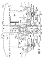
- FIG 3 is a schematic cross section of a connection assembly according to the invention.
- This connection assembly comprises a female connector 15 and a male connector 18.
- the female connector comprises a housing 16 provided with an inlet window 17 allowing the insertion of a male connector 18.
- This window 17 is located on one side front of the housing 16.
- the latter can be fixed by snap-fastening, on a support 22 shown in non-detailed manner in the figure.
- the support 22 can for example be fixed to a partition in a building.
- the female connector also includes, inside this housing and facing the window, a first group of connection terminals such as 28 and a second group of connection terminals such as 29, respectively connected, as will be seen more far in detail, at the corresponding ends of lines such as 32, 33 of the first and second successive sections 7, 8 of the network cable of FIG. 1.
- the male connector 18 is shown at 26 in its insertion position in the female connector.
- This male connector has connection terminals 21 which come into sliding contact with the corresponding connection terminals 28 of the female connector.
- connection terminals 21 make it possible to connect a terminal to the sections 7, 8 of the network, by a multiline connection cable 5 with ground shielding.
- the terminals 21 are of the "insulation piercing" type; they are in contact with each conductor 10 of the connection cable of the additional unit or apparatus, by virtue of the piercing of the insulating sheath 11 surrounding the conductor 10.
- the retractable movable means 35 give the connector, as will be seen in detail below, its universal character. They make it possible to ensure the continuity of the transmissions on the network, in particular between the stations or terminals connected to the sections 7, 8 of cable of this network, before the insertion of the male connector; they also make it possible to manage the connections of the lines of the connection cable 5 with the lines of the cable sections 7, 8 of the network, as well as the interconnections between the lines of the network cable sections, after insertion of the male connector into the female connector . Other lines of the network cable sections, and other contacts not referenced, are represented in FIG. 3.
- connection assembly further comprises a shield 23 of the connection terminals of the female connector.
- This shield forms a sheath at least partially enveloping a first and a second group of connection terminals 28, 29 of the female connector located opposite the window 17, inside the housing 15.
- the male connector 18 also includes a shield. external 24 which forms a sheath at least partially enveloping the connection terminals 21 of this connector.
- This sheath can for example be a metallized layer deposited on the insulating support 25 of the connection terminals 21.
- This support is moreover provided with an elastic lever 26 allowing the male connector to be held in position in the female connector, thanks to its snap-fastening on the front face of the housing 16.
- the metallized sheath 24 is brought into contact, by crimping, in a manner not shown in the figure, with the shielding 13, 14 (FIG. 2) of the connection cable 5.
- the shielding sheath 24 of the male connector comes into contact, during insertion, with the shielding sheath 23 of the female connector. Good electrical contact between these two sleeves is ensured, for example, by means of two elastic tabs such as 27 and 75, as will be seen more clearly with reference to the description of FIG. 6, produced in the sleeve 23 and based on the shield sheath 24 of the male connector, on either side of the latter.
- connection assembly also includes means which will be described later in relation to FIG. 5, to ensure electrical continuity between the shield 23 of the female connector and the shield of each section of the network.
- These means notably comprise connection terminals of the female connector, contacts connected to these terminals and respectively connected to conductive shielding lines of the cable sections 7, 8 of the network, and an electrical connection jumper belonging to retractable mobile means 35 internal to the female connector.
- Figure 4 is a more detailed schematic cross section of the connection assembly of the invention. This figure will allow better understand the structure of the retractable mobile means 35 which make it possible to ensure the continuity of the transmissions on the network before insertion of the male connector and the establishment of the connections between the network and the terminal connected to the male connector, during the insertion of that -this in the female connector. The same elements have the same references in this figure and in Figure 3.
- the terminals 28 of the first group of connection terminals of the female connector are connected respectively by first connection means, at the ends of lines, such as line 32, of the first section 7 of the network cable. These first connection means will be described later in detail.
- the terminals 29 of the second group of connection terminals of the female connector are respectively connected by second connection means which will be described later in detail, at the ends of lines, such as line 33, of the second section 8 of the network cable. .
- the terminals 28, 29 of the first and second groups are located respectively opposite each other.
- each cable section such as that which has been described in FIG. 2 has eight lines
- the first and second groups of terminals 28, 29 respectively comprise eight terminals. Only one terminal of each group is shown in this figure.
- the electrical connection means 35 mobile and retractable move by sliding between the first and second groups of terminals 28, 29, under the thrust of the male connector 18, during insertion.
- These retractable means comprise an insulating support 36 and a group of jumpers for electrical connections such as 37, 38, in the form of a U for example.
- Each rider has two branches of identical lengths. Before complete insertion of the male connector 18 into the female connector, the two branches 37A and 37B or 38A and 38B of each jumper such as 37 or 38 are respectively in contact with a terminal such as 28 of the first group and a terminal such as 29 of the second group, whatever the length L1 or L2 of the branches of the jumper considered, this length being measured parallel to the longitudinal axis X′X of the female connector.
- the branches of all the riders of the group can all have the same first length L1 (such as the jumper 37 in the figure), or all have the same second length L2 (such as the jumper 38) less than the first length L1. It is also possible that for the group of jumpers held by the insulating support 36, jumpers of a first set have branches having the first length L1 and jumpers of a second set have branches having the second length L2. This possibility of choosing the lengths of the branches of the jumpers gives the connection assembly its universal character.
- the terminals 21 of the male connector respectively come into sliding contact with the terminals 28 of the first group of the female connector, at the time of insertion of the male connector.
- the retractable movable means 35 are shown in this figure in the retracted position, the male connector 18 being inserted into the female connector. (These retractable means are in the so-called “free” or “not pressed in” position, when the male connector is not inserted). They are pushed by a spring 39 bearing on the bottom of a housing 40 made in two insulating support blocks 41, 47 whose structure will be described later in detail.
- the first connection means comprise a first group of line contacts such as the contact 43, passing through a first insulating support block 41 made integral with the housing 16 by means which are not shown in detail in the figure. These line contacts of the first group lead respectively to a first and a second face 44, 45 of this first support block.
- the second connection means comprise a second group of line contacts, such as the contact 46, which pass through the second insulating support block 47, which can be joined to the housing 16. These contacts 46 of the second group, respectively lead to first and second faces 48, 49 of the second support block 47.
- the contacts 43 of the first group are respectively connected on the side of the first face 44 of the first support block 41, at the ends of the lines, such as 32, of the first section of the network cable 7.
- the contacts 46 of the second group are respectively connected on the side of the first face 48 of the second support block 47, at the ends of lines such as 33 of the second section of cable 8 of the network.
- the contacts 43 of the first group are connected, on the side of the second face 45 of the first support block 41, to a first circuit 50.
- This first circuit is a printed circuit having tracks respectively connected to the connection terminals 28 of the first group and to the ends of the contacts 43 so as to ensure the electrical connection between the terminals 28 of the first group and the lines 32 of the first section 7 of the network cable.
- the contacts 46 of the second group are connected respectively, on the side of the first face 48 of the second support block 47, to the line ends 33 of the second cable section 8 of the network. These contacts are also connected, on the side of the second face 49 of the second support block 47, to a second circuit 51 which is a printed circuit having tracks respectively connected to the terminals 29 of connection of the second group. In this way the electrical connection is ensured between the connection terminals 29 of the second group 29 and the lines 33 of the second section of cable 8 of the network.
- the first faces 44, 48 of the first and second support blocks 41, 47 are located respectively opposite two internal lateral faces of the housing 16.
- the second faces 45, 49 of the first and second support blocks 41, 47 are located opposite one from the other.
- the housing 40 contains the two printed circuits and the two blocks can be assembled and positioned by means of positioning pins not referenced.
- Each line contact such as the contacts 43, 46 of the first and second groups, is a self-stripping contact with a cutting fork 55.
- the end of each line such as 32, of the first or second section is inserted into this fork which cuts the insulating sheath surrounding the conductor of this line; electrical contact is ensured by pinching the driver in the fork.
- insulating insertion pushers such as the pushbutton 56 which has an opening 57 having a dimension close to that of the insulating sheath of line 32
- the end of line 32 is introduced into this opening which is thus made integral with the pusher.
- the insertion of this pusher into a housing 58 surrounding the contact in the corresponding support block 41 or 47, on the side of the first face 44 or 48 of this support block, causes the insulating sheath to be cut by the cutting fork 55 , as well as the pinching of the conductor surrounded by it.
- the housings 58 of the pushers 56 extend towards the rear face of the housing 16, in the direction of the arrow 59, by gutters not shown in this figure; they respectively make it possible to contain the lines of the considered section of each cable, in the vicinity of their ends.
- Figure 5 shows schematically and in cross section a partial view of the female connector in the vicinity of the shielding sleeve 23.
- the same elements have the same references in this figure and in the previous figures.
- the means which make it possible to ensure electrical continuity between the shield 23 of the female connector and the shield of each section of the network comprise in each of the two support blocks 41, 47, an additional contact and push button, of structure and arrangement identical to those of each push button and line contact described above.
- FIG. 5 This figure does not show the additional pushers which are identical to the pushers 56 of the previous figure.
- Contacts additional are shown at 60, 61 in FIG. 5.
- Each contact is connected on the side of the first face of the support block which corresponds to it to a screen line in contact with the screen of the corresponding section of cable of the network.
- the additional contact 60 is connected to a line 62 of the first section 7 of the network (FIG. 4). This line in fact corresponds to line 13 in FIG. 2.
- the additional contact 61 of the second support block 47 is connected to a screen line 63 in contact with the screen of the second section of cable 8 of the network. (figure 2).
- Each additional contact is connected on the side of the second face 45 or 49 of the support block 41 or 47 which corresponds to it, to an additional track of the corresponding printed circuit.
- the additional contact 60 is connected, on the side of the second face 45 of the first support block 41, to an additional track 65 of the first printed circuit 50.
- the additional contact 61 is connected, on the side of the second face 49 of the second block 47, to an additional track 66 of the second printed circuit 51.
- the additional track 65 of the first printed circuit 50 is connected to the shielding sheath 23 of the female connector, for example by a metal tongue 67 having a fork at its end 68; this fork clamps the additional track 65, so as to ensure electrical continuity between the shielding line 62 of the first network section 7 and the shielding sheath 23, via the additional contact 60.
- the additional track 66 connected to the shielding line 63 of the second section 8 of the network cable is here connected to the shielding sheath 23 of the female connector by an assembly which comprises: a additional terminal 70 of the second group of connection terminals of the female connector, an additional connection jumper 71 of the retractable mobile means 35, and an additional terminal 72 of the first group of connection terminals of the female connector, connected to the additional track 65 of the first printed circuit 50.
- the additional jumper 71 is in permanent contact, before and after insertion, with the additional terminals 70 and 72, whether the male connector is inserted or not in the female connector.
- Shielding continuity is thus permanently ensured between the shielding of the female connector and the shields of the network cable sections when the male connector is inserted into the female connector, the outer shielding 24 (FIG. 3) of this connector comes into contact with the shield 23 of the female connector; the retractable means 35 are pushed by the male connector and ensure, thanks to the additional jumper 71, the electrical continuity between the shield 24 of the male connector, the shield 23 of the female connector, and the shield lines 62, 63 of the sections network cable.
- the additional jumper 71 has a shape identical to that of the connecting jumpers 37 in FIG. 4.
- the continuity of the shielding between the shielding sheath 23 and the shielding lines 62, 63 of the network cables, could be ensured without using additional connection terminals and additional jumper; it would be possible, for example, to implement a second tongue of the sheath 23, comparable to the tongue 67, and having a fork in contact with the additional track 66 of the second printed circuit 50. It would also be possible to ensure the continuity of the shields thanks to connection wires connecting the sheath 23 to each of the additional tracks 65, 66 of the first and second printed circuits 50, 51.
- FIG. 6 is a schematic longitudinal section which represents the interior of the female connector, in a plane close to the second face 45 of the first support block 41 and mobile means 35.
- the same elements have the same references in this figure and on the previous figures. It is assumed that the male connector 18 is not completely inserted into the female connector. We can see in this figure the shielding sheath 23 of the female connector, the first group of connection terminals 28 and the contact tabs 27, 75. The mobile means have also been shown in their two positions, retracted A or free B 35. A distinction is also made in this figure, for example a first set of link jumpers 37 having the first length L1, a second set of link jumpers 38 having the second length L2, less than the first length.
- connection between the ends of terminals 28 of the first group and connection pads 73 of the first printed circuit 50 We also distinguish the connection between the ends of terminals 28 of the first group and connection pads 73 of the first printed circuit 50.
- additional track 65 of the first printed circuit 50 in contact with the tongue 67 which electrically connects this track additional with the shielding sheath 23.
- the connecting tracks 74 of the printed circuit Partially shown are the connecting tracks 74 of the printed circuit, which make it possible to connect the terminals 28 of the first group with the contacts 43 which ensure the connection with the lines of the first section of cable 7.
- the additional track 65 is connected to the additional terminal 72 of the first group; there is also shown the additional jumper 71 ensuring electrical continuity between the additional terminal 72 of the first group and the additional terminal 70 of the second group ( Figure 5).
- connection assembly of the invention also comprises in the window 17, which allows the insertion of the male connector, polarizing means whose role will be better understood with the aid of FIGS. 7 and 8.
- the window 17 is shown face on these two figures while the male connector is shown very schematically at 18. The same elements have the same references in these figures and in the previous figures.
- the male connector is a connector intended for the connection of a telephone terminal for example, on a telephone network.
- the connector is intended for the connection of a data processing terminal on a computer network.
- the cross section of the male connector has a keying boss 80, flowing in a corresponding slide 81 of the window 17, while in Figure 7 the cross section of the male connector does not have this keying boss .
- a keying means constituted for example by an elastic jumper 82 is therefore introduced into the slide 81 shown in FIG.
- window 17 includes a retractable shutter at the time of insertion of the male connector.
- This retractable shutter can be constituted by a sliding shutter 83, pushed by a spring 84, integral with the housing 16. This spring makes it possible to close the window 17 using the shutter 83, in the absence of a male connector and can open this window when a male connector is to be inserted into the female connector.
- connection assembly of the invention makes possible, which depend on the lengths of the connection jumpers used in the retractable mobile means 35, will be better understood with the aid of FIGS. 9A, 9B, ... , 11B, 11C. These various figures make it possible in particular to show the universal appearance of this connection assembly. The same elements have the same references in these figures and in the previous figures.
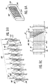
- FIG. 9A shows schematically and in perspective, a first embodiment of the retractable mobile means 35 of FIG. 4.
- the insulating support 36 carries a group 90 of identical jumpers 37, identical.
- Each rider has the shape of a U whose two branches have the same first length L1; there is also shown an additional jumper 71 which ensures, as indicated above, the continuity of the mass shields and whose branches also have the first length L1.
- FIG. 9B shows schematically and in perspective, the group 90 of jumpers 37 in FIG. 9A, the first group 91 of connection terminals 28 and the second group 92 of connection terminals 29 of the female connector.
- the additional terminal 72 of the first group and the additional terminal 70 of the second group; these additional terminals ensure, by contact with the additional jumper 71, the electrical continuity of the earth shields.
- the jumpers 37 of the group 90, as well as the additional jumper 71 are shown in solid lines when the support 36 is in the free position (that is to say not pressed into the female connector, before insertion of the male connector). These jumpers are shown in broken lines when the support 36 is in the retracted position (that is to say pressed into the female connector, after insertion of the male connector).
- connection terminals 21 of the male connector has also been shown diagrammatically, which when inserted, are respectively in contact with the corresponding terminals 28 of the first group of the female connector.
- the terminals 28 of the first group 90, and all the corresponding terminals 29 respectively of the second group 91 are in permanent electrical connection, whatever the free or retracted position of the support 36, the first length of the connecting jumpers being chosen accordingly. It is the same for the additional terminals 70 and 72 which ensure the continuity of the ground shields, by permanent contact with the additional jumper 72.
- the connections obtained in this embodiment are shown diagrammatically in FIG. 9C.
- the connection assembly 4 is represented schematically by a group 96 of switches 94 connected respectively to the cable sections 7, 8 of the network.
- the additional switch 95 is connected to the shielding lines of each section.
- the stations 2 and 3 of the network have also been represented, as well as the terminal 6 connected to the network by the multiline cable. 5, also comprising a ground shielding line.
- the insertion of the male connector does not cause any break in the connections between the lines of sections 7, 8 of the network.
- the switches 94 of the group 96 are therefore all in the closed position and schematically represent the continuity of the electrical connections respectively between the terminals 28 of the first group 91 and the terminals 29 of the second group 92; the continuity of the earth shields is represented by the closed position of the switch 95.
- connection cable 5 and the additional screen line of this cable are respectively connected, to the transmission lines and to the screen line of each cable section. There is no break in the links on the network.
- FIG. 10A shows schematically and in perspective, a second embodiment of the retractable mobile means 35 of FIG. 4.
- the insulating support 36 carries a group 90 of link jumpers 37, which are identical.
- Each jumper has the shape of a U, the two branches of which have the same second length L2, less than the first length L1 of the jumpers of FIG. 9A.
- the additional jumper 71 which ensures, as indicated above, the continuity of the ground shields.
- the branches of this additional jumper are of first length L1, greater than the second length L2.
- FIG. 10B shows schematically and in perspective, the group 90 of jumpers 38 of FIG. 10A, the first group 91 of connection terminals 28, the second group 92 of connection terminals 29 of the female connector.
- the additional terminal 72 of the first group and the additional terminal 70 of the second group of terminals which ensure, by contact with the additional jumper 71, the electrical continuity of the earth shields.
- the jumpers 38 of the group 90, as well as the additional jumper 71 are shown in solid lines when the support 36 is in the free position (that is to say not pressed into the female connector, before insertion of the male connector). These jumpers are shown in broken lines when the support 36 is in the retracted position (that is to say pressed into the female connector, after insertion of the male connector).
- connection terminals 21 of the male connector has also been shown diagrammatically, which when inserted, are respectively in contact with the corresponding terminals 28 of the first group of the female connector.
- the terminals 28 of the first group 90, and all the corresponding terminals 29 respectively of the second group 91 are in permanent electrical connection, the support 36 not being pressed into the female connector . It is the same for the additional terminals 70 and 72 which ensure the continuity of the ground shields, by permanent contact with the additional jumper 72 whose branches are of first length (length of the branches of the jumpers of FIG. 9A). After insertion, due to the shorter length L2 of the jumpers 38, there is a break in all the links in the network, with the exception of the ground shielding link.
- Connection assembly 4 is shown schematically by a group 96 of switches 94 respectively connected to the cable sections 7, 8 of the network.
- the additional switch 95 is connected to the shielding lines of each section.
- the switches 94 of group 96 are therefore all in the open position and schematically represent the interruption of the electrical connections, respectively between the terminals 28 of the first group 91 and the terminals 29 of the second group 92; the continuity of the earth shields is represented by the closed position of the switch 95.
- connection cable 5 on insertion, the transmission lines of the connection cable 5 are respectively connected to the lines of the cable section 7.
- the electrical shielding continuity is ensured between the cable sections 7, 8, and the cable 5.
- the terminal 6 is therefore connected to all the lines of the cable section 7 of the network and can communicate with the station 2, while the communication is interrupted on the network, between the stations 2 and 3.
- FIG. 11A shows schematically and in perspective, a third embodiment of the retractable mobile means 35 of FIG. 4.
- the insulating support 36 carries a group 90 of connecting jumpers which comprises a first set of jumpers 37 having branches of first length L1 (length of the branches of the jumpers of FIG. 9A), and a second set of jumpers 38 having branches of second length L2 (length of the branches of the jumpers of FIG. 10A).
- FIG. 11B schematically and in perspective represents the group 90 comprising a set of jumpers 37 of first length L1 and a set of jumpers 38 of second length L2, the first group 91 of connection terminals 28 and the second group 92 of connection terminals 29 of the female connector. Also shown in this figure is the additional terminal 72 of the first group and the additional terminal 70 of the second group of terminals which ensure, by contact with the additional jumper 71, the electrical continuity of the ground shields.
- jumpers 37 and 38 of each set of the group of jumpers 90, as well as the additional jumper 71 are shown in solid lines when the support 36 is in the free position (that is to say not pressed into the female connector, before insertion male connector). These jumpers are shown in broken lines when the support 36 is in the retracted position (that is to say pressed into the female connector, after insertion of the male connector).
- connection terminals 21 of the male connector has also been shown diagrammatically, which when inserted, are respectively in contact with the corresponding terminals 28 of the first group of the female connector.
- the terminals 28 of the first group 90, and all the corresponding terminals 29 of the second group 91 respectively are in permanent electrical connection. It is the same for the additional terminals 70 and 72 which ensure the continuity of the earth shields, by permanent contact with the additional jumper 72.
- the connections are interrupted on the lines of the network which are connected to the connection terminals of the female connector which respectively correspond to the jumpers 38 of the second set.
- the links are maintained on the lines of the network connected to the connection terminals of the female connector, which respectively correspond to the jumpers 37 of the first set.
- connection assembly 4 is represented diagrammatically by a group 96 of switches connected respectively to the cable sections 7, 8 of the network.
- the additional switch 95 is connected to the shielding lines of each section.
- the insertion of the male connector cuts the connections between the lines of the sections 7, 8 of the network which correspond respectively to the jumpers 38, which is shown diagrammatically in the figure by a set of open switches 98.
- connections are on the contrary maintained on the lines of the network which respectively correspond to the jumpers 37, which is shown diagrammatically on the figure by a set of closed switches 99.
- the continuity of the ground shields is represented by the closed position of the switch 95 .
- terminal 6 is connected to all lines of section 7, and partially connected to lines of section 8.
- the support 36 includes notches and openings not referenced, making it possible to maintain the jumpers on this support.
- connection assembly which has just been described does indeed have a universality character since it allows all the possible combinations of connections of a terminal on a network, while providing the possibility of obtaining continuity of the ground shields. .
Description
La présente invention concerne un ensemble universel de connexion, pour raccorder un terminal de traitement à un réseau de transmissions de données.The present invention relates to a universal connection assembly, for connecting a processing terminal to a data transmission network.
Cette invention s'applique aux réseaux de transmissions de données utilisant des câbles multilignes et plus particulièrement des câbles multilignes dits à "paires torsadées" comportant un blindage de masse supprimant les bruits parasites dans les transmissions. Dans ce type de câble, la transmission de données s'effectue dans un sens dans l'une des lignes de chaque paire, et dans un sens opposé, dans l'autre ligne de cette paire.This invention applies to data transmission networks using multiline cables and more particularly so-called "twisted pair" multiline cables comprising a mass shielding suppressing parasitic noise in transmissions. In this type of cable, data transmission takes place in one direction in one of the lines of each pair, and in an opposite direction, in the other line of this pair.
On sait que les réseaux peuvent être locaux ou non et permettent des transmissions de données informatiques (les réseaux connus par exemple sous les dénominations STARLAN, ETHERNET, TOKEN RING, etc...) ou des transmissions de données téléphoniques numériques (par exemple le réseau RNIS de réseau numérique à intégration de service) ; il est indispensable de pouvoir raccorder en dérivation sur chaque réseau, et de façon simple, un ou plusieurs "équipements terminaux de traitement de données" (en abrégé ETTD), informatiques et/ ou téléphoniques, selon le type de réseau considéré. Ces équipements terminaux de traitements de données sont aussi appelés "Data Terminal Equipment" en anglais (ou en abrégé DTE), ou encore terminal ou encore station.We know that networks can be local or not and allow computer data transmissions (networks known for example under the names STARLAN, ETHERNET, TOKEN RING, etc.) or digital telephone data transmissions (for example the network ISDN integrated service digital network); it is essential to be able to connect in branch on each network, and in a simple way, one or more "terminal data processing equipment" (abbreviated as DTE), IT and / or telephone, depending on the type of network considered. These terminal data processing equipment are also called "Data Terminal Equipment" in English (or abbreviated to DTE), or terminal or station.
Ce raccordement d'un terminal à un réseau pose des problèmes spécifiques à chaque réseau, qui sont dus notamment à l'architecture du réseau considéré (architecture en étoile, en bus, en arbre, ...etc) et au type d'interface de liaison utilisé dans le réseau (liaisons normalisées V11 ou V24 par exemple). En effet, le raccordement d'un terminal à un réseau s'effectue grâce à un ensemble de connexion approprié, comportant un connecteur femelle relié à deux tronçons successifs de ce réseau, et un connecteur mâle relié au terminal. Cet ensemble de connexion doit assurer la continuité des transmissions de données sur le réseau, avant le raccordement du terminal par insertion du connecteur mâle dans le connecteur femelle, et, selon l'architecture du réseau et le type d'interface, permettre au moment de cette insertion, une coupure totale ou partielle des transmissions sur le réseau pour dévier totalement ou partiellement ces transmissions vers le terminal, ou au contraire, ne provoquer aucune coupure des transmissions sur le réseau.This connection of a terminal to a network poses problems specific to each network, which are due in particular to the architecture of the network considered (star, bus, tree architecture, etc.) and the type of link interface used in the network (standardized links V11 or V24 for example). Indeed, the connection of a terminal to a network is effected by means of an appropriate connection assembly, comprising a female connector connected to two successive sections of this network, and a male connector connected to the terminal. This connection assembly must ensure the continuity of data transmissions on the network, before connecting the terminal by inserting the male connector into the female connector, and, depending on the network architecture and the type of interface, allow when this insertion, a total or partial cut of the transmissions on the network to totally or partially divert these transmissions to the terminal, or on the contrary, does not cause any cut of the transmissions on the network.
Un autre problème apparaît lorsque les tronçons de câbles multilignes utilisés pour les transmissions sur le réseau, et pour la connexion d'un terminal sur ce réseau, sont pourvus d'un blindage de masse. Il est en effet indispensable dans ce cas, d'assurer une continuité électrique des blindages des tronçons de câbles du réseau et du câble de connexion. Il est aussi indispensable de prévoir un blindage de bornes de connexion du connecteur mâle, externe à ce connecteur, et un blindage des bornes de connexion du connecteur femelle, interne à ce connecteur, ces blindages externe et interne devant être reliés aux blindages des câbles du réseau et au blindage du câble de connexion du terminal.Another problem arises when the multi-line cable sections used for transmissions on the network, and for the connection of a terminal on this network, are provided with ground shielding. It is indeed essential in this case to ensure electrical continuity of the shields of the sections of network cables and of the connection cable. It is also essential to provide a shield for connection terminals of the male connector, external to this connector, and a shield for the connection terminals of the female connector, internal to this connector, these external and internal shields having to be connected to the shields of the cables of the network and shielding of the terminal connection cable.
Enfin un autre problème apparaît du fait qu'une norme internationale récente dite ISO8877, relative aux ensembles de connexion utilisables dans les réseaux, définit notamment pour chaque ensemble l'emplacement des bornes de connexion du connecteur femelle et du connecteur mâle, la forme externe du connecteur mâle et la forme d'une fenêtre d'entrée sur une face avant du connecteur femelle, permettant l'insertion du connecteur mâle.Finally, another problem appears from the fact that a recent international standard known as ISO8877, relating to connection assemblies usable in networks, defines in particular for each assembly the location of the connection terminals of the female connector and the male connector, the external shape of the male connector and the shape of an entry window on a front face of the female connector, allowing the insertion of the male connector.
Il n'existe actuellement aucun ensemble de connexion, qui puisse être qualifié d'universel, c'est-à-dire qui permette le branchement d'un terminal sur un réseau avec coupure totale ou partielle, ou sans coupure des transmissions sur le réseau, qui assure une continuité des blindages des câbles de transmissions du réseau et de connexion du terminal ainsi que des blindages des connecteurs mâle et femelle. Il n'existe pas non plus d'ensemble de connexion présentant toutes les caractéristiques de transmissions et de continuité de blindages mentionnées plus haut, tout en respectant la norme ISO8877. Il n'existe pas non plus d'ensemble de connexion comportant des moyens de détrompage permettant d'éviter le branchement d'un terminal informatique sur une prise de type téléphonique.There is currently no set of connections, which can be described as universal, that is to say which allows the connection of a terminal on a network with total or partial interruption, or without interruption of transmissions on the network. , which ensures continuity of the shields of the network communication cables and terminal connection as well as the shields of the male and female connectors. There is also no connection assembly with all the transmission characteristics and shielding continuity mentioned above, while respecting ISO8877 standard. There is also no connection assembly comprising coding means making it possible to avoid the connection of a computer terminal to a telephone type socket.
L'invention a pour but de remédier à ces inconvénients grâce à un ensemble de connexion universel, s'adaptant à tout type de réseau, permettant un branchement d'un terminal en dérivation, sur le réseau avec coupure totale ou partielle, ou sans coupure des transmissions sur le réseau.The object of the invention is to remedy these drawbacks by means of a universal connection assembly, adapting to any type of network, allowing connection of a branch terminal, to the network with total or partial interruption, or without interruption. transmissions on the network.
Cet ensemble de connexion permet en outre, dans le cas où les câbles de transmission du réseau et le câble de connexion du terminal comportent un blindage de masse, d'assurer une continuité de ce blindage avec des blindages des bornes de connexion des connecteurs mâle et femelle. Enfin, cet ensemble de connexion, tout en ayant ces caractéristiques, obéit à la norme ISO8877.This connection assembly also makes it possible, in the case where the network transmission cables and the terminal connection cable comprise a ground shield, to ensure continuity of this shield with shields of the connection terminals of the male connectors and female. Finally, this connection assembly, while having these characteristics, obeys the ISO8877 standard.
L'invention a plus précisément pour objet un ensemble universel de connexion, pour raccorder un terminal de traitement à un réseau de transmissions de données par câble multilignes, comportant :
- un connecteur femelle comprenant un boîtier muni d'une fenêtre d'entrée sur une face avant de ce boîtier et, à l'intérieur de ce boîtier et en regard de la fenêtre, des bornes de connexion respectivement reliées à des extrémités correspondantes de lignes de transmission d'un premier et d'un deuxième tronçons successifs de câbles du réseau ;
- un connecteur mâle comportant des bornes de connexion respectivement reliées à des lignes d'un câble de connexion multilignes dudit terminal, les bornes de connexion du connecteur mâle entrant respectivement en contact, par glissement, avec des bornes correspondantes du connecteur femelle, lors de l'insertion du connecteur mâle dans ladite fenêtre, pour raccorder le terminal au réseau;
- un premier groupe de bornes de connexion du connecteur femelle respectivement reliées par des premiers moyens de connexion avec les extrémités correspondantes des lignes du câble du premier tronçon et entrant respectivement en contact avec les bornes de connexion du connecteur mâle lors de ladite insertion ;
- un deuxième groupe de bornes de connexion du connecteur femelle respectivement reliées par des seconds moyens de connexion, avec des extrémités correspondantes des lignes du câble du deuxième tronçon ;
- et des moyens de liaisons électriques, mobiles et rétractables sous la poussée du connecteur mâle à l'insertion, internes au connecteur femelle et se déplaçant entre les bornes des premier et deuxième groupes du connecteur femelle, pour assurer la continuité des communications sur le réseau avant ladite insertion et pour assurer le raccordement du terminal avec le réseau, après ladite insertion.
- a female connector comprising a housing provided with an input window on a front face of this housing and, inside this housing and facing the window, connection terminals respectively connected to corresponding ends of lines of transmission of first and second successive sections of network cables;
- a male connector comprising connection terminals respectively connected to lines of a multiline connection cable of said terminal, the connection terminals of the male connector respectively coming into contact, by sliding, with corresponding terminals of the female connector, during the insertion of the male connector in said window, for connecting the terminal to the network;
- a first group of connection terminals of the female connector respectively connected by first connection means with the corresponding ends of the lines of the cable of the first section and respectively coming into contact with the connection terminals of the male connector during said insertion;
- a second group of connection terminals of the female connector respectively connected by second connection means, with corresponding ends of the lines of the cable of the second section;
- and means of electrical connections, mobile and retractable under the push of the male connector on insertion, internal to the female connector and moving between the terminals of the first and second female connector groups, to ensure continuity of communications on the network before said insertion and to ensure the connection of the terminal with the network, after said insertion.
Selon un mode de réalisation de l'invention, les moyens mobiles de liaisons électriques comportent un support mobile poussé par le connecteur mâle lors de l'invention, et un groupe de cavaliers de liaisons électriques, chaque cavalier ayant deux branches respectivement en contact avec une borne du premier groupe et avec une borne correspondante du deuxième groupe du connecteur femelle, avant l'insertion, ces cavaliers ayant tous des branches d'une première longueur, ou tous d'une deuxième longueur inférieure à la première longueur, ou ce groupe de cavaliers formant un premier ensemble de cavaliers ayant des branches de la première longueur et un deuxième ensemble de cavaliers ayant des branches de la deuxième longueur.According to one embodiment of the invention, the mobile means of electrical connections comprise a mobile support pushed by the male connector during the invention, and a group of jumpers of electrical connections, each jumper having two branches respectively in contact with a terminal of the first group and with a corresponding terminal of the second group of the female connector, before insertion, these jumpers all having branches of a first length, or all of a second length less than the first length, or this group of jumpers forming a first set of jumpers having branches of the first length and a second set of jumpers having branches of the second length.
Selon un autre mode de réalisation, l'ensemble de connexion comporte :
- un blindage des bornes de connexion du connecteur femelle formant un fourreau enveloppant au moins partiellement les bornes de connexion du connecteur femelle à l'intérieur dudit boîtier et des moyens pour assurer la continuité électrique du blindage du connecteur femelle avec des lignes de blindage respectives des premier et deuxième tronçons de câbles du réseau,
- un blindage externe au connecteur mâle formant un autre fourreau enveloppant partiellement les bornes du connecteur mâle, ce fourreau étant en contact avec une ligne de blindage dudit câble de connexion du terminal et entrant en contact avec le blindage du connecteur femelle, lors de l'insertion.
- a shielding of the connection terminals of the female connector forming a sheath at least partially enveloping the connection terminals of the female connector inside said housing and means for ensuring the electrical continuity of the shielding of the female connector with respective shielding lines of the first and second sections of network cables,
- a shield external to the male connector forming another sheath partially enveloping the terminals of the male connector, this sheath being in contact with a shield line of said terminal connection cable and coming into contact with the shield of the female connector, during insertion .
D'autres caractéristiques et avantages de l'invention ressortiront mieux de la description qui va suivre, donnée en référence aux dessins annexés dans lesquels :
- la figure 1 représente schématiquement un réseau de transmission de données dans lequel intervient un ensemble de connexion conforme à l'invention,
- la figure 2 représente schématiquement et en coupe transversale un câble multi-lignes avec blindage de masse, utilisé dans un réseau de communications dans lequel intervient l'ensemble de connexion de l'invention,
- la figure 3 représente schématiquement et en coupe transversale un ensemble de connexion conforme à l'invention, le connecteur mâle étant inséré dans le connecteur femelle,
- la figure 4 représente schématiquement et en coupe transversale, un ensemble de connexion conforme à l'invention, le connecteur mâle n'étant pas inséré dans le connecteur femelle,
- la figure 5 représente schématiquement et en coupe transversale, l'intérieur du connecteur femelle, au voisinage des moyens de blindage internes,
- la figure 6 représente schématiquement et en coupe longitudinale les moyens de liaisons mobiles et rétractables intervenant dans le connecteur femelle de l'invention,
- les figures 7 et 8 représentent schématiquement la fenêtre d'insertion apparaissant sur une face avant du connecteur femelle, cette fenêtre étant pourvue de moyens de détrompage, pour des applications différentes de l'ensemble de connexion,
- les figures 9A, 10A, 11A représentent schématiquement et en perspective différents modes de réalisation des moyens de liaison rétractables de l'ensemble de connexion de l'invention, qui permettent de rendre cet ensemble universel dans ses applications,
- les figures 9B, 10B, 11B représentent schématiquement et en perspective, respectivement pour les modes de réalisation précédents, les cavaliers de liaisons utilisés dans les moyens mobiles rétractables, et leurs positions vis-à-vis des bornes de connexion du connecteur femelle, lorsque les moyens mobiles sont en position rétractée ou en position libre,
- les figures 11A, 11B, 11C représentent schématiquement, respectivement pour les modes de réalisation précédents, les différents types de raccordement d'un terminal avec le réseau, obtenus pour chaque mode de réalisation.
- FIG. 1 diagrammatically represents a data transmission network in which a connection assembly according to the invention operates,
- FIG. 2 schematically represents in cross section a multi-line cable with ground shielding, used in a communications network in which the connection assembly of the invention operates,
- FIG. 3 shows schematically and in cross section a connection assembly in accordance with the invention, the male connector being inserted into the female connector,
- FIG. 4 diagrammatically shows in cross section a connection assembly in accordance with the invention, the male connector not being inserted in the female connector,
- FIG. 5 shows diagrammatically and in cross section, the interior of the female connector, in the vicinity of the internal shielding means,
- FIG. 6 schematically represents in longitudinal section the means of mobile and retractable connections intervening in the female connector of the invention,
- FIGS. 7 and 8 schematically represent the insertion window appearing on a front face of the female connector, this window being provided with polarizing means, for applications different from the connection assembly,
- FIGS. 9A, 10A, 11A show schematically and in perspective different embodiments of the retractable connecting means of the connection assembly of the invention, which make this assembly universal in its applications,
- FIGS. 9B, 10B, 11B show schematically and in perspective, respectively for the preceding embodiments, the jumpers for connections used in the retractable movable means, and their positions with respect to the connection terminals of the female connector, when the mobile means are in the retracted position or in the free position,
- FIGS. 11A, 11B, 11C schematically represent, respectively for the previous embodiments, the different types of connection of a terminal with the network, obtained for each embodiment.
La figure 1 représente schématiquement un réseau 1 de transmission de données entre deux stations 2, 3 communiquant au moyen d'un câble multilignes ayant par exemple un blindage de masse. Ce câble sera décrit plus loin en détail. L'ensemble de connexion 4 de l'invention permet de brancher, en dérivation sur ce réseau, par un câble de connexion 5, un autre terminal ou une autre station 6. Cet ensemble de connexion comporte un connecteur femelle relié à deux tronçons successifs 7, 8 du câble de communications du réseau, et un connecteur mâle relié au câble de connexion 5. Le câble de connexion 5, comme les tronçons de câbles 7, 8 de transmission du réseau, est de préférence un câble multilignes avec blindage de masse.FIG. 1 schematically represents a
La figure 2 est une coupe schématique transversale de l'un des tronçons 7 ou 8 du câble de transmissions du réseau, ou du câble de connexion 5. Ce câble comporte ici huit lignes conductrices telles que la ligne 9, constituées chacune d'un conducteur 10 entouré d'une gaine isolante 11. Ce câble peut être qualifié de câble à quatre paires torsadées. Il comporte aussi un blindage de masse 12, constitué par exemple par une enveloppe métallique enroulée autour des lignes 9. Au moins une ligne conductrice 13 de blindage, en contact avec l'enveloppe métallique 12, facilite l'interconnexion des blindages de masse de différents tronçons du câble. Une gaine isolante 14 entoure l'enveloppe de blindage 12 et la ligne conductrice de blindage 13. Dans ce type de câble multilignes, comme indiqué plus haut, certaines lignes sont destinées à assurer des transmissions dans un premier sens, tandis que d'autres lignes sont destinées à assurer des transmissions dans un sens opposé. La ligne de blindage de masse est généralement reliée à la masse du terminal ou de la station connecté à ce câble. Toutefois cette ligne de blindage peut dans certains cas, véhiculer un signal.Figure 2 is a schematic cross section of one of the
La figure 3 est une coupe schématique transversale d'un ensemble de connexion conforme à l'invention. Cet ensemble de connexion comporte un connecteur femelle 15 et un connecteur mâle 18. Le connecteur femelle comprend un boîtier 16 muni d'une fenêtre d'entrée 17 permettant l'insertion d'un connecteur mâle 18. Cette fenêtre 17 est située sur une face avant du boîtier 16. Ce dernier peut être fixé par encliquetage, sur un support 22 représenté de manière non détaillée sur la figure. Le support 22 peut être par exemple, fixé à une cloison dans un immeuble. Le connecteur femelle comprend aussi, à l'intérieur de ce boîtier et en regard de la fenêtre, un premier groupe de bornes de connexion telles que 28 et un deuxième groupe de bornes de connexion telles que 29, respectivement reliées, comme on le verra plus loin en détail, aux extrémités correspondantes de lignes telles que 32, 33 du premier et du deuxième tronçons successifs 7, 8 du câble du réseau de la figure 1.Figure 3 is a schematic cross section of a connection assembly according to the invention. This connection assembly comprises a
Le connecteur mâle 18 est représenté en 26 dans sa position d'insertion dans le connecteur femelle. Ce connecteur mâle comporte des bornes de connexion 21 qui entrent en contact par glissement avec les bornes de connexion 28 correspondantes du connecteur femelle. Ces bornes de connexion 21 permettent de relier un terminal aux tronçons 7, 8 du réseau, par un câble de connexion multilignes 5 à blindage de masse. Les bornes 21 sont du type "à percement d'isolant" ; elles sont en contact avec chaque conducteur 10 du câble de connexion de l'unité ou appareil supplémentaire, grâce au percement de la gaine isolante 11 entourant le conducteur 10.The
Les moyens mobiles rétractables 35 confèrent au connecteur comme on le verra plus loin en détail, son caractère universel. Ils permettent d'assurer la continuité des transmissions sur le réseau, notamment entre les stations ou terminaux reliés aux tronçons 7, 8 de câble de ce réseau, avant l'insertion du connecteur mâle ; ils permettent aussi de gérer les connexions des lignes du câble de connexions 5 avec les lignes des tronçons de câble 7, 8 du réseau, ainsi que les interconnexions entre les lignes des tronçons de câble du réseau, après insertion du connecteur mâle dans le connecteur femelle. D'autres lignes des tronçons de câble du réseau, et d'autres contacts non référencés, sont représentés sur la figure 3.The retractable movable means 35 give the connector, as will be seen in detail below, its universal character. They make it possible to ensure the continuity of the transmissions on the network, in particular between the stations or terminals connected to the
Dans un mode de réalisation de l'invention, l'ensemble de connexion comporte en outre un blindage 23 des bornes de connexion du connecteur femelle. Ce blindage forme un fourreau enveloppant au moins partiellement un premier et un deuxième groupes de bornes de connexion 28,29 du connecteur femelle situées en regard de la fenêtre 17, à l'intérieur du boîtier 15. Le connecteur mâle 18 comporte lui aussi un blindage externe 24 qui forme un fourreau enveloppant au moins partiellement les bornes de connexion 21 de ce connecteur. Ce fourreau peut être par exemple une couche métallisée déposée sur le support isolant 25 des bornes de connexion 21. Ce support est d'ailleurs muni d'un levier élastique 26 permettant le maintien en position du connecteur mâle dans le connecteur femelle, grâce à son encliquetage sur la face avant du boîtier 16. Le fourreau métallisé 24 est mis en contact, par sertissage, de manière non représentée sur la figure, avec le blindage 13, 14 (figure 2) du câble de connexion 5.In one embodiment of the invention, the connection assembly further comprises a
Le fourreau de blindage 24 du connecteur mâle entre en contact, lors de l'insertion, avec le fourreau de blindage 23 du connecteur femelle. Un bon contact électrique entre ces deux fourreaux est assuré par exemple, grâce à deux languettes élastiques telles que 27 et 75, comme on le verra mieux en se référant à la description de la figure 6, réalisées dans le fourreau 23 et s'appuyant sur le fourreau de blindage 24 du connecteur mâle, de part et d'autre de celui-ci.The shielding
L'ensemble de connexion comporte aussi des moyens qui seront décrits plus loin en relation avec la figure 5, pour assurer la continuité électrique entre le blindage 23 du connecteur femelle et le blindage de chaque tronçon du réseau. Ces moyens comportent notamment des bornes de connexion du connecteur femelle, des contacts reliés à ces bornes et reliés respectivement à des lignes de blindage conductrices des tronçons de câble 7, 8 du réseau, et un cavalier de liaison électrique appartenant à des moyens mobiles rétractables 35 internes au connecteur femelle.The connection assembly also includes means which will be described later in relation to FIG. 5, to ensure electrical continuity between the
La figure 4 est une coupe schématique transversale, plus détaillée, de l'ensemble de connexion de l'invention. Cette figure va permettre de mieux comprendre la structure des moyens mobiles rétractables 35 qui permettent d'assurer la continuité des transmissions sur le réseau avant insertion du connecteur mâle et l'établissement des liaisons entre le réseau et le terminal relié au connecteur mâle, lors de l'insertion de celui-ci dans le connecteur femelle. Les mêmes éléments portent les mêmes références sur cette figure et sur la figure 3.Figure 4 is a more detailed schematic cross section of the connection assembly of the invention. This figure will allow better understand the structure of the retractable mobile means 35 which make it possible to ensure the continuity of the transmissions on the network before insertion of the male connector and the establishment of the connections between the network and the terminal connected to the male connector, during the insertion of that -this in the female connector. The same elements have the same references in this figure and in Figure 3.
Les bornes 28 du premier groupe de bornes de connexion du connecteur femelle sont reliées respectivement par des premiers moyens de connexion, aux extrémités de lignes, telles que la ligne 32, du premier tronçon 7 du câble du réseau. Ces premiers moyens de connexion seront décrits plus loin en détail.The
Les bornes 29 du deuxième groupe de bornes de connexion du connecteur femelle, sont respectivement reliées par des seconds moyens de connexion qui seront décrits plus loin en détail, aux extrémités de lignes, telles que la ligne 33, du deuxième tronçon 8 du câble du réseau. Les bornes 28, 29 des premier et deuxième groupes sont situées respectivement en regard les unes des autres.The
Si chaque tronçon de câble, tel que celui qui a été décrit à la figure 2 comporte huit lignes, les premier et deuxième groupes de bornes 28, 29 comportent respectivement huit bornes. Une seule borne de chaque groupe est représentée sur cette figure.If each cable section, such as that which has been described in FIG. 2, has eight lines, the first and second groups of
Les moyens de liaisons électriques 35, mobiles et rétractables se déplacent par glissement entre les premier et deuxième groupes de bornes 28, 29, sous la poussée du connecteur mâle 18, lors de l'insertion. Ces moyens rétractables comportent un support isolant 36 et un groupe de cavaliers de liaisons électriques tels que 37, 38, en forme de U par exemple. Chaque cavalier comporte deux branches de longueurs identiques. Avant insertion complète du connecteur mâle 18 dans le connecteur femelle, les deux branches 37A et 37B ou 38A et 38B de chaque cavalier tel que 37 ou 38 sont respectivement en contact avec une borne telle que 28 du premier groupe et une borne telle que 29 du deuxième groupe, quelle que soit la longueur L1 ou L2 des branches du cavalier considéré, cette longueur étant mesurée parallèlement à l'axe longitudinal X′X du connecteur femelle. En effet, pour des raisons qui seront indiquées plus loin les branches de tous les cavaliers du groupe peuvent toutes présenter une même première longueur L1 (tel que le cavalier 37 sur la figure), ou toutes présenter une même deuxième longueur L2 (tel que le cavalier 38) inférieure à la première longueur L1. Il est également possible que pour le groupe de cavaliers maintenus par le support isolant 36, des cavaliers d'un premier ensemble présentent des branches ayant la première longueur L1 et des cavaliers d'un deuxième ensemble présentent des branches ayant la deuxième longueur L2. Cette possibilité de choix de longueurs des branches des cavaliers confère à l'ensemble de connexion son caractère universel. En effet, c'est grâce à ce choix, comme on le verra plus loin en détail, qu'il est possible après insertion du connecteur mâle d'assurer les transmissions de données au terminal et d'assurer aussi une continuité des transmissions sur toutes les lignes du réseau reliées au connecteur femelle, ou au contraire une coupure totale ou partielle des transmissions sur les lignes du réseau.The electrical connection means 35, mobile and retractable move by sliding between the first and second groups of
Comme représenté sur la figure, les bornes 21 du connecteur mâle entrent respectivement en contact par glissement, avec les bornes 28 du premier groupe du connecteur femelle, au moment de l'insertion du connecteur mâle.As shown in the figure, the
Les moyens mobiles rétractables 35 sont représentés sur cette figure en position rétractée, le connecteur mâle 18 étant inséré dans le connecteur femelle. (Ces moyens rétractables sont en position dite "libre" ou "non enfoncé", lorsque le connecteur mâle n'est pas inséré). Ils sont poussés par un ressort 39 prenant appui sur le fond d'un logement 40 réalisé dans deux blocs supports isolants 41, 47 dont la structure sera décrite plus loin en détail.The retractable
Les premiers moyens de connexion comportent un premier groupe de contacts de lignes tels que le contact 43, traversant un premier bloc-support isolant 41 rendu solidarisable du boîtier 16 par des moyens qui ne sont pas représentés en détail sur la figure. Ces contacts de ligne du premier groupe débouchent respectivement sur une première et une deuxième faces 44, 45 de ce premier bloc-support. De la même manière, les deuxièmes moyens de connexion comportent un deuxième groupe de contacts de lignes, tels que le contact 46, qui traversent le deuxième bloc-support isolant 47, solidarisable du boîtier 16. Ces contacts 46 du deuxième groupe, débouchent respectivement sur une première et une deuxième faces 48, 49 du deuxième bloc-support 47.The first connection means comprise a first group of line contacts such as the
Les contacts 43 du premier groupe sont respectivement reliés du côté de la première face 44 du premier bloc-support 41, aux extrémités des lignes, telles que 32, du premier tronçon du câble 7 du réseau. De la même manière, les contacts 46 du deuxième groupe sont respectivement reliés du côté de la première face 48 du deuxième bloc-support 47, aux extrémités de lignes telles que 33 du deuxième tronçon de câble 8 du réseau.The
Les contacts 43 du premier groupe sont reliés, du côté de la deuxième face 45 du premier bloc-support 41, à un premier circuit 50. Ce premier circuit est un circuit imprimé ayant des pistes respectivement reliées aux bornes de connexion 28 du premier groupe et aux extrémités des contacts 43 de façon à assurer la liaison électrique entre les bornes 28 du premier groupe et les lignes 32 du premier tronçon 7 de câble du réseau.The
De la même manière, les contacts 46 du deuxième groupe, sont reliés respectivement, du côté de la première face 48 du deuxième bloc-support 47, aux extrémités de ligne 33 du deuxième tronçon de câble 8 du réseau. Ces contacts sont d'autre part reliés, du côté de la deuxième face 49 du deuxième bloc-support 47, à un deuxième circuit 51 qui est un circuit imprimé présentant des pistes respectivement reliées aux bornes 29 de connexion du deuxième groupe. De cette manière la liaison électrique est assurée entre les bornes de connexion 29 du deuxième groupe 29 et les lignes 33 du deuxième tronçon de câble 8 du réseau.Likewise, the
Les premières faces 44, 48 des premier et deuxième blocs-supports 41, 47 sont situées respectivement en regard de deux faces latérales internes du boîtier 16. Les deuxièmes faces 45, 49 des premier et deuxième blocs-supports 41, 47 sont situées en regard l'une de l'autre. Le logement 40 contient les deux circuits imprimés et les deux blocs peuvent être assemblés et positionnés grâce à des pions de positionnement non référencés.The first faces 44, 48 of the first and second support blocks 41, 47 are located respectively opposite two internal lateral faces of the
Chaque contact de ligne, tel que les contacts 43, 46 des premier et deuxième groupes, est un contact auto-dénudant à fourche coupante 55. L'extrémité de chaque ligne telle que 32, du premier ou deuxième tronçon est insérée dans cette fourche qui découpe la gaine isolante entourant le conducteur de cette ligne ; le contact électrique est assuré par pincement du conducteur dans la fourche.Each line contact, such as the
Cette insertion, ainsi que le maintien en position de chaque ligne, sont facilités par l'utilisation de poussoirs isolants d'insertion, tels que le poussoir 56 qui comporte une ouverture 57 ayant une dimension voisine de celle de la gaine isolante de la ligne 32. L'extrémité de la ligne 32 est introduite dans cette ouverture qui est ainsi rendue solidaire du poussoir. L'enfoncement de ce poussoir dans un logement 58 entourant le contact dans le bloc-support correspondant 41 ou 47, du côté de la première face 44 ou 48 de ce bloc-support, provoque le découpage de la gaine isolante par la fourche coupante 55, ainsi que le pincement du conducteur entouré par celle-ci. Les logements 58 des poussoirs 56 se prolongent vers la face arrière du boîtier 16, dans le sens de la flèche 59, par des gouttières non représentées sur cette figure ; elles permettent respectivement de contenir les lignes du tronçon considéré de chaque câble, au voisinage de leurs extrémités.This insertion, as well as the maintenance in position of each line, are facilitated by the use of insulating insertion pushers, such as the
La figure 5 représente schématiquement et en coupe transversale une vue partielle du connecteur femelle au voisinage du fourreau de blindage 23. Les mêmes éléments portent les mêmes références sur cette figure et sur les figures précédentes. Les moyens qui permettent d'assurer la continuité électrique entre le blindage 23 du connecteur femelle et le blindage de chaque tronçon du réseau comportent dans chacun des deux bloc-supports 41, 47, un contact et un poussoir supplémentaires, de structure et d'agencement identiques à ceux de chaque poussoir et contact de ligne décrits plus haut.Figure 5 shows schematically and in cross section a partial view of the female connector in the vicinity of the shielding
Sur cette figure, on n'a pas représenté les poussoirs supplémentaires qui sont identiques aux poussoirs 56 de la figure précédente. Les contacts supplémentaire sont représentés en 60, 61 sur la figure 5. Chaque contact est relié du côté de la première face du bloc-support qui lui correspond à une ligne de blindage en contact avec le blindage du tronçon de câble correspondant du réseau. C'est ainsi par exemple que le contact suppplémentaire 60 est relié à une ligne 62 du premier tronçon 7 du réseau (figure 4). Cette ligne correspond en fait à la ligne 13 de la figure 2. De la même manière, le contact supplémentaire 61 du deuxième bloc-support 47 est relié à une ligne de blindage 63 en contact avec le blindage du deuxième tronçon de câble 8 du réseau (figure 2).This figure does not show the additional pushers which are identical to the
Chaque contact supplémentaire est relié du côté de la deuxième face 45 ou 49 du bloc-support 41 ou 47 qui lui correspond, à une piste supplémentaire du circuit imprimé correspondant. C'est ainsi par exemple que le contact supplémentaire 60 est relié, du côté de la deuxième face 45 du premier bloc-support 41, à une piste supplémentaire 65 du premier circuit imprimé 50. De la même manière le contact supplémentaire 61 est relié, du côté de la deuxième face 49 du deuxième bloc 47, à une piste supplémentaire 66 du deuxième circuit imprimé 51. La piste supplémentaire 65 du premier circuit imprimé 50 est reliée au fourreau de blindage 23 du connecteur femelle, par exemple par une languette métallique 67 présentant une fourche à son extrémité 68 ; cette fourche pince la piste supplémentaire 65, de manière à assurer la continuité électrique entre la ligne 62 de blindage du premier tronçon de réseau 7 et le fourreau de blindage 23, par l'intermédiaire du contact supplémentaire 60.Each additional contact is connected on the side of the
La piste supplémentaire 66 reliée à la ligne de blindage 63 du deuxième tronçon 8 de câble du réseau, est reliée ici au fourreau de blindage 23 du connecteur femelle par un montage qui comporte : une borne supplémentaire 70 du deuxième groupe de bornes de connexion du connecteur femelle, un cavalier de liaison supplémentaire 71 des moyens mobiles rétractable 35, et une borne suppplémentaire 72 du premier groupe de borne de connexion du connecteur femelle, reliée à la piste supplémentaire 65 du premier circuit imprimé 50. Le cavalier supplémentaire 71 est en contact permanent, avant et après insertion, avec les bornes supplémentaires 70 et 72, que le connecteur mâle soit inséré ou non dans le connecteur femelle. Une continuité de blindage est ainsi assurée en permanence entre le blindage du connecteur femelle et les blindages des tronçons de câble du réseau lorsque le connecteur mâle est inséré dans le connecteur femelle, le blindage extérieur 24 (figure 3) de ce connecteur entre en contact avec le blindage 23 du connecteur femelle ; les moyens rétractables 35 sont poussés par le connecteur mâle et permettent d'assurer, grâce au cavalier supplémentaire 71, la continuité électrique entre le blindage 24 du connecteur mâle, le blindage 23 du connecteur femelle, et les lignes de blindage 62, 63 des tronçons de câble du réseau. Le cavalier supplémentaire 71 présente une forme identique à celle des cavaliers de liaison 37 de la figure 4.The
La continuité du blindage entre le fourreau de blindage 23 et les lignes de blindage 62, 63 des câbles du réseau, pourrait être assurée sans utiliser de bornes de connexion supplémentaires et de cavalier supplémentaire ; il serait possible par exemple, de mettre en oeuvre une deuxième languette du fourreau 23, comparable à la languette 67, et présentant une fourche en contact avec la piste supplémentaire 66 du deuxième circuit imprimé 50. Il serait également possible d'assurer la continuité des blindages grâce à des fils de connexion reliant le fourreau 23 à chacune des pistes supplémentaires 65, 66 des premier et second circuits imrimés 50, 51.The continuity of the shielding between the shielding
La figure 6 est une coupe schématique longitudinale qui représente l'intérieur du connecteur femelle, dans un plan voisin de la deuxième face 45 du premier bloc-support 41 et des moyens mobiles 35. Les mêmes éléments portent les mêmes références sur cette figure et sur les figures précédentes. On suppose que le connecteur mâle 18 n'est pas complètement inséré dans le connecteur femelle. On distingue sur cette figure le fourreau de blindage 23 du connecteur femelle, le premier groupe de bornes de connexion 28 et les languettes de contact 27, 75. On a également représenté dans leurs deux positions, rétractée A, ou libre B, les moyens mobiles 35. On distingue aussi sur cette figure, par exemple un premier ensemble de cavalier 37 de liaison ayant la première longueur L1, un deuxième ensemble de cavaliers de liaison 38 ayant la deuxième longueur L2, inférieure à la première longueur. On distingue également la liaison entre les extrémités des bornes 28 du premier groupe et des plots de connexion 73 du premier circuit imprimé 50. On remarque également la piste supplémentaire 65 du premier circuit imprimé 50, en contact avec la languette 67 qui relie électriquement cette piste supplémentaire avec le fourreau de blindage 23. On a représenté partiellement les pistes de liaison 74 du circuit imprimé, qui permettent de relier les bornes 28 du premier groupe avec les contacts 43 qui assurent la liaison avec les lignes du premier tronçon de câble 7. Comme représenté schématiquement en traits interrompus 76, la piste supplémentaire 65 est reliée à la borne supplémentaire 72 du premier groupe ; on a également représenté le cavalier supplémentaire 71 assurant la continuité électrique entre la borne supplémentaire 72 du premier groupe et la borne supplémentaire 70 du deuxième groupe (figure 5).FIG. 6 is a schematic longitudinal section which represents the interior of the female connector, in a plane close to the
L'ensemble de connexion de l'invention comporte aussi dans la fenêtre 17, qui permet l'insertion du connecteur mâle, des moyens de détrompage dont le rôle sera mieux compris à l'aide des figures 7 et 8. La fenêtre 17 est représentée de face sur ces deux figures tandis que le connecteur mâle est représenté très schématiquement en 18. Les mêmes éléments portent les mêmes références sur ces figures et sur les figures précédentes.The connection assembly of the invention also comprises in the
Sur la figure 7 le connecteur mâle est un connecteur destiné au branchement d'un terminal téléphonique par exemple, sur un réseau téléphonique. Sur la figure 8 le connecteur est destiné au branchement d'un terminal de traitement de données sur un réseau informatique. On voit sur la figure 8 que la section transversale du connecteur mâle présente un bossage de détrompage 80, circulant dans une glissière correspondante 81 de la fenêtre 17, alors que sur la figure 7 la section transversale du connecteurr mâle ne possède pas ce bossage de détrompage. Pour éviter le branchement d'un terminal de traitement de données informatiques sur un réseau de transmissions de données téléphoniques par exemple, on introduit donc dans la glissière 81 représentée sur la figure 7, un moyen de détrompage constitué par exemple par un cavalier élastique 82, occupant cette glissière ; ce cavalier interdit le branchement, sur un réseau téléphonique par exemple, d'un terminal informatique relié à un connecteur mâle présentant un bossage de détrompage 80. Il est également possible de coller sur la face avant du boîtier 16, une étiquette indiquant le type de réseau auquel le connecteur femelle est relié.In FIG. 7, the male connector is a connector intended for the connection of a telephone terminal for example, on a telephone network. In FIG. 8, the connector is intended for the connection of a data processing terminal on a computer network. We see in Figure 8 that the cross section of the male connector has a keying
Enfin, et tel que représenté sur la figure 3, la fenêtre 17 comporte un obturateur rétractable au moment de l'insertion du connecteur mâle. Cet obturateur rétractable peut être constitué par un volet à glissière 83, poussé par un ressort 84, solidaire du boîtier 16. Ce ressort permet de fermer la fenêtre 17 à l'aide du volet 83, en l'absence de connecteur mâle et peuvent ouvrir cette fenêtre lorsqu'un connecteur mâle doit être inséré dans le connecteur femelle.Finally, and as shown in Figure 3,
Les différents branchements que permet d'effectuer l'ensemble de connexion de l'invention, qui dépendent des longueurs des cavaliers de liaisons utilisés dans les moyens mobiles rétractables 35, seront mieux compris à l'aide des figures 9A, 9B, ..., 11B, 11C. Ces différentes figures permettent notamment de faire apparaître l'aspect universel de cet ensemble de connexion. Les mêmes éléments portent les mêmes références sur ces figures et sur les figures précédentes.The different connections which the connection assembly of the invention makes possible, which depend on the lengths of the connection jumpers used in the retractable mobile means 35, will be better understood with the aid of FIGS. 9A, 9B, ... , 11B, 11C. These various figures make it possible in particular to show the universal appearance of this connection assembly. The same elements have the same references in these figures and in the previous figures.
La figure 9A représente schématiquement et en perspective, un premier mode de réalisation des moyens mobiles rétractables 35 de la figure 4. Dans ce mode de réalisation, le support isolant 36 porte un groupe 90 de cavaliers de liaison 37, identiques. Chaque cavalier a la forme d'un U dont les deux branches ont la même première longueur L1 ; on a également représenté un cavalier supplémentaire 71 qui permet d'assurer comme indiqué plus haut, la continuité des blindages de masse et dont les branches ont elles aussi, la première longueur L1. La figure 9B représente schématiquement et en perspective, le groupe 90 de cavaliers 37 de la figure 9A, le premier groupe 91 de bornes de connexion 28 et le deuxième groupe 92 de bornes de connexion 29 du connecteur femelle. On a aussi représenté sur cette figure, la borne supplémentaire 72 du premier groupe et la borne supplémentaire 70 du deuxième groupe ; ces bornes supplémentaires assurent, par contact avec le cavalier supplémentaire 71, la continuité électrique des blindages de masse. Les cavaliers 37 du groupe 90, ainsi que le cavalier supplémentaire 71 sont représentés en traits pleins lorsque le support 36 est en position libre (c'est-à-dire non enfoncé dans le connecteur femelle, avant insertion du connecteur mâle). Ces cavaliers sont représentés en traits interrompus lorsque le support 36 est en position rétractée (c'est-à-dire enfoncé dans le connecteur femelle, après insertion du connecteur mâle).FIG. 9A shows schematically and in perspective, a first embodiment of the retractable mobile means 35 of FIG. 4. In this embodiment, the insulating
On a aussi représenté schématiquement le groupe 93 de bornes de connexion 21 du connecteur mâle, qui à l'insertion, sont respectivement en contact avec les bornes correspondantes 28 du premier groupe du connecteur femelle.The
Dans ce mode de réalisation, avant et après insertion du connecteur mâle, les bornes 28 du premier groupe 90, et toutes les bornes 29 respectivement correspondantes du deuxième groupe 91, sont en liaison électrique permanente, quelle que soit la position libre ou rétractée du support 36, la première longueur des cavaliers de liaison étant choisie en conséquence. Il en est de même pour les bornes supplémentaires 70 et 72 qui assurent la continuité des blindages de masse, par contact permanent avec le cavalier supplémentaire 72. Les branchements obtenus dans ce mode de réalisation sont schématisés sur la figure 9C. L'ensemble de connexion 4 est représenté schématiquement par un groupe 96 d'interrupteurs 94 reliés respectivement aux tronçons de câble 7, 8 du réseau. L'interrupteur supplémentaire 95 est relié aux lignes de blindage de chaque tronçon. On a aussi représenté les stations 2 et 3 du réseau, ainsi que le terminal 6 raccordé au réseau par le câble multilignes 5, comportant lui aussi une ligne de blindage de masse. Comme indiqué plus haut, l'insertion du connecteur mâle ne provoque aucune coupure des liaisons entre les lignes des tronçons 7, 8 du réseau. Les interrupteurs 94 du groupe 96, sont donc tous en position fermée et représentent schématiquement la continuité des liaisons électriques respectivement entre les bornes 28 du premier groupe 91 et les bornes 29 du second groupe 92 ; la continuité des blindages de masse est représentée par la position fermée de l'interrupteur 95.In this embodiment, before and after insertion of the male connector, the
Dans ce mode de réalisation, à l'insertion, les lignes de transmission du câble de connexion 5 et la ligne supplémentaire de blindage de ce câble, sont respectivement connectées, aux lignes de transmission et à la ligne de blindage de chaque tronçon de câble. Il n'y a aucune coupure des liaisons sur le réseau.In this embodiment, on insertion, the transmission lines of the
La figure 10A représente schématiquement et en perspective, un deuxième mode de réalisation des moyens mobiles rétractables 35 de la figure 4. Dans ce mode de réalisation, le support isolant 36 porte un groupe 90 des cavaliers de liaison 37, identiques. Chaque cavalier a la forme d'un U dont les deux branches ont la même deuxième longueur L2, inférieure à la première longueur L1 des cavaliers de la figure 9A. On a également représenté le cavalier supplémentaire 71 qui permet d'assurer comme indiqué plus haut, la continuité des blindages de masse. Les branches de ce cavalier supplémentaire sont de première longueur L1, supérieure à la deuxième longueur L2.FIG. 10A shows schematically and in perspective, a second embodiment of the retractable mobile means 35 of FIG. 4. In this embodiment, the insulating
La figure 10B représente schématiquement et en perspective, le groupe 90 de cavaliers 38 de la figure 10A, le premier groupe 91 de bornes de connexion 28, le deuxième groupe 92 de bornes de connexion 29 du connecteur femelle. On a aussi représenté sur cette figure, la borne supplémentaire 72 du premier groupe et la borne supplémentaire 70 du deuxième groupe de bornes qui assurent, par contact avec le cavalier supplémentaire 71, la continuité électrique des blindages de masse. Les cavaliers 38 du groupe 90, ainsi que le cavalier supplémentaire 71 sont représentés en traits pleins lorsque le support 36 est en position libre (c'est-à-dire non enfoncé dans le connecteur femelle, avant insertion du connecteur mâle). Ces cavaliers sont représentés en traits interrompus lorsque le support 36 est en position rétractée (c'est-à-dire enfoncé dans le connecteur femelle, après insertion du connecteur mâle).FIG. 10B shows schematically and in perspective, the
On a aussi représenté schématiquement le groupe 93 de bornes de connexion 21 du connecteur mâle, qui à l'insertion, sont respectivement en contact avec les bornes correspondantes 28 du premier groupe du connecteur femelle.The
Dans ce mode de réalisation, avant insertion du connecteur mâle, les bornes 28 du premier groupe 90, et toutes les bornes 29 respectivement correspondantes du deuxième groupe 91, sont en liaison électrique permanente, le support 36 n'étant pas enfoncé dans le connecteur femelle. Il en est de même pour les bornes supplémentaires 70 et 72 qui assurent la continuité des blindages de masse, par contact permanent avec le cavalier supplémentaire 72 dont les branches sont de première longueur (longueur des branches des cavaliers de la figure 9A). Après insertion, du fait de la plus faible longueur L2 des cavaliers 38, il y a coupure de toutes les liaisons du réseau, à l'exception de la liaison de blindage de masse.In this embodiment, before insertion of the male connector, the
Les branchements obenus dans ce mode de réalisation sont schématisés sur la figure 10C. L'ensemble de connexion 4 est représenté schématiquement par un groupe 96 d'interrupteurs 94 reliés respectivement aux tronçons de câble 7, 8 du réseau. L'interrupteur supplémentaire 95 est relié aux lignes de blindage de chaque tronçon. Dans ce mode de réalisation, l'insertion du connecteur mâle provoque la coupure totale des liaisons entre les lignes des tronçons 7, 8 du réseau. Les interrupteurs 94 du groupe 96, sont donc tous en position ouverte et représentent schématiquement la coupure des liaisons électriques, respectivement entre les bornes 28 du premier groupe 91 et les bornes 29 du second groupe 92 ; la continuité des blindages de masse est représentée par la position fermée de l'interrupteur 95.The connections obtained in this embodiment are shown diagrammatically in FIG. 10C. Connection assembly 4 is shown schematically by a
Dans ce mode de réalisation, à l'insertion, les lignes de transmission du câble de connexion 5 sont respectivement raccordées aux lignes du tronçon de câble 7. La continuité électrique de blindage est assurée entre les tronçons de câble 7, 8, et le câble de connexion 5. Le terminal 6 est donc raccordé à toutes les lignes du tronçon de câble 7 du réseau et peut communiquer avec la station 2, tandis que la communication est interrompue sur le réseau, entre les stations 2 et 3.In this embodiment, on insertion, the transmission lines of the
La figure 11A représente schématiquement et en perspective, un troisième mode de réalisation des moyens mobiles rétractables 35 de la figure 4. Dans ce mode de réalisation, le support isolant 36 porte un groupe 90 de cavaliers de liaison qui comporte un premier ensemble de cavaliers 37 ayant des branches de première longueur L1 (longueur des branches des cavaliers de la figure 9A), et un deuxième ensemble de cavaliers 38 ayant des branches de deuxième longueur L2 (longueur des branches des cavaliers de la figure 10A).FIG. 11A shows schematically and in perspective, a third embodiment of the retractable mobile means 35 of FIG. 4. In this embodiment, the insulating
On a également représenté le cavalier supplémentaire 71 qui permet d'assurer, comme indiqué plus haut, la continuité des blindages de masse. Les branches de ce cavalier sont de première longueur L1. La figure 11B représente schématiquement et en perspective le groupe 90 comprenant un ensemble de cavaliers 37 de première longueur L1 et un ensemble de cavaliers 38 de deuxième longueur L2, le premier groupe 91 de bornes de connexion 28 et le deuxième groupe 92 de bornes de connexion 29 du connecteur femelle. On a aussi représenté sur cette figure la borne supplémentaire 72 du premier groupe et la borne supplémentaire 70 du deuxième groupe de bornes qui assurent, par contact avec le cavalier supplémentaire 71, la continuité électrique des blindages de masse. Les cavaliers 37 et 38 de chaque ensemble du groupe de cavaliers 90, ainsi que le cavalier supplémentaire 71 sont représentés en traits pleins lorsque le support 36 est en position libre (c'est-à-dire non enfoncé dans le connecteur femelle, avant insertion du connecteur mâle). Ces cavaliers sont représentés en traits interrompus lorsque le support 36 est en position rétractée (c'est-à-dire enfoncé dans le connecteur femelle, après insertion du connecteur mâle).There is also shown the
On a aussi représenté schématiquement le groupe 93 de bornes de connexion 21 du connecteur mâle, qui à l'insertion, sont respectivement en contact avec les bornes correspondantes 28 du premier groupe du connecteur femelle.The
Dans ce mode de réalisation, avant insertion du connecteur mâle, les bornes 28 du premier groupe 90, et toutes les bornes 29 respectivement correspondantes du deuxième groupe 91, sont en liaison électrique permanente. Il en est de même pour les bornes supplémentaires 70 et 72 qui assurent la continuité des blindages de masse, par contact permanent avec le cavalier supplémentaire 72. Après insertion du connecteur mâle, les liaisons sont interrompues sur les lignes du réseau qui sont reliées aux bornes de connexion du connecteur femelle qui correspondent respectivement aux cavaliers 38 du deuxième ensemble. Par contre les liaisons sont maintenues sur les lignes du réseau reliées aux bornes de connexion du connecteur femelle, qui correspondent respectivement aux cavaliers 37 du premier ensemble.In this embodiment, before insertion of the male connector, the
Les branchements obtenus dans ce mode de réalisation sont schématisés sur la figure 11C. L'ensemble de connexion 4 est représenté schématiquement par un groupe 96 d'interrupteurs reliés respectivement aux tronçons de câble 7, 8 du réseau. L'interrupteur supplémentaire 95 est relié aux lignes de blindage de chaque tronçon. Comme indiqué plus haut, l'insertion du connecteur mâle provoque la coupure des liaisons entre les lignes des tronçons 7, 8 du réseau qui correspondent respectivement aux cavaliers 38, ce qui est schématisé sur la figure par un ensemble d'interrupteurs ouverts 98. Les liaisons sont au contraire maintenues sur les lignes du réseau qui correspondent respectivement aux cavaliers 37, ce qui est schématisé sur la figurre par un ensemble d'interrupteurs fermés 99. La continuité des blindages de masse est représentée par la position fermée de l'interrupteur 95.The connections obtained in this embodiment are shown diagrammatically in FIG. 11C. The connection assembly 4 is represented diagrammatically by a
Dans ce mode de réalisation, il y a coupure partielle des liaisons sur le réseau (sur les lignes des tronçons 7 et 8 respectivement reliées aux bornes 28, 29 correspondant respectivement à l'ensemble de cavaliers 38 de deuxième longueur) et maintien partiel de ces liaisons (sur les lignes des tronçons 7 et 8 respectivement reliées aux bornes 28, 29, correspondant respectivement à l'ensemble de cavaliers 37 de première longueur). Le terminal 6 est raccordé à toutes les lignes du tronçon 7, et partiellement raccordé aux lignes du tronçons 8.In this embodiment, there is a partial cut of the connections on the network (on the lines of the
Dans tous les modes de réalisation, le support 36 comporte des encoches et des ouvertures non référencées, permettant de maintenir les cavaliers sur ce support.In all the embodiments, the
L'ensemble de connexion qui vient d'être décrit présente bien un caractère d'universalité puisqu'il permet toutes les combinaisons possibles de branchements d'un terminal sur un réseau, tout en fournissant la possibilité d'obtenir une continuité des blindages de masse.The connection assembly which has just been described does indeed have a universality character since it allows all the possible combinations of connections of a terminal on a network, while providing the possibility of obtaining continuity of the ground shields. .
Claims (16)
- Universal connection assembly for connecting a processing terminal to a data transmision network by multiline cable comprising:
a female connector (15) having a box (16) provided with an inlet window (17) on a front face of said box and, within the box and facing the window, connection terminals (28,29) respectively connected to corresponding ends (32,33) of transmission lines of a first and a second successive sections (7,8) of cables of the network;
a male connector (18) having connection terminals (21) respectively connected to lines of a multiline connection cable (5) of said terminal (6), the connection terminals (21) of the male connector respectively coming into contact, by sliding, with the corresponding terminals (28) of the female connector, during the insertion of the male connector into said window for connecting the terminal to the network;
a first group of connection terminals (28) of the female connector respectively connected by first connection means (43,50) to the corresponding ends of cable lines of the first section (7) and respectively coming into contact with the connection terminals (21) of the male connector during said insertion;
a second group of connection terminals (29) of the female connector respectively connected by second connection means (46,51) to corresponding ends of the lines of the cable of the second section (8); and electrical linking means (35), which are mobile and retractable under the thrust of the male connector on insertion, located within the female connector and moving between the terminals (28,29) of the first and second groups of the female connector, in order to ensure the continuity of communications on the network prior to said insertion and for ensuring the connection of the terminal (6) to the network after said insertion. - Connection assembly according to claim 1, characterized in that the mobile means of the electrical links (35) have a mobile support (36) moved by the male connector (18) during insertion and a group (90) of electric U-links, each link having two branches respectively in contact with a terminal (28) of the first group and with a corresponding terminal (29) of the second group of the female connector, prior to insertion, all or some of the U-links of said group having branches (37A, 37B - 38A, 38B) of a first and/or a second length (L1, L2).
- Connection assembly according to claim 2, characterized in that the U-links (37) have all the branches (37A, 38B) of the first length (L1) for ensuring the continuity of the electrical connection, after insertion, between the terminals (28) of the first group of the female connector and the respectively corresponding terminals (29) of the second group of the female connector.
- Connection assembly according to claim 2, characterized in that the U-links (38) have all branches (38A, 38B) of the second length (L2) so that, after insertion, the electrical links are interrupted between the terminals (28) of the first group of the female connector and the respectively corresponding terminals (29) of the second group of the female connector.
- Connection assembly according to claim 2, characterized in that the U-links (37) of the first assembly have branches (37A, 37B) of the first length (L1) and U-links (38) of the second assembly have branches (37A, 38B) of the second length (L2) so that, after insertion, they ensure the continuity of the electrical connections respectively between the terminals of a first terminal assembly (28, 29) of the first and second groups of the female connector and in order to interrupt the electrical connections respectively between the terminals of a second terminal assembly (28, 29) of the first and second groups of the female connector.
- Connector assembly according to claim 2, characterized in that it comprises:
a shield (23) for the connection terminals (28, 29) of the female connector forming a sleeve at least partly enveloping the connection terminals of the female connector within said said box and means (61, 62, 65, 67, 70, 71, 72, 66) for ensuring the electrical continuity of the shield of the female connector with the respective shielding lines (62, 63) of the first and second sections of cables of the network,
a shield (24) outsides the male connector forming another sleeve partly enveloping the terminals (21) of the male connector, said sleeve being in contact with a shielding line of said connecting cable (5) of the terminal (6) and coming into contact with the shield (23) of the female connector during insertion. - Connection assembly according to any one of the claims 2 to 6, characterized in that the first and second connection means respectively incorporate a first and a second group of contacts (43, 46) of lines respectively traversing a first and a second support blocks (41, 47), which are of an insulating nature and can be integrated with the box, said contacts respectively issuing onto a first and second faces (44, 45) or (48, 49) of each support block, the contacts of lines (43, 46) of the first and second groups being respectively connected, from the side of the first face (44 or 48) of each support block (41 or 47), to the ends of the lines (32, 33) of the first and second network sections (7, 8) and being respectively connected, from the side of the second face (45 or 49) of each support block, to a first and a second circuits (50, 51) respectively connecting the terminals (28) of the first group to the contacts of the lines (43) of the first group and the terminals (29) of the second group to the contacts of the lines (46) of the second group.
- Connection assembly according to claim 7, characterized in that the first faces (44, 48) of the first and second support blocks (41, 47) are respectively positioned facing two internal side faces of the box (16), the second faces (45, 49) of the first and second support blocks facing one another, the first and second circuits (50, 51) being printed circuits having tracks respectively connected to the terminals (28, 29) of the first and second groups of terminals of the female connector.
- Connection assembly according to claim 4, characterized in that each contacts of lines (43 or 46) of the first and second groups is a cutting fork self-baring contact (55) in which is inserted the end of the corresponding line of the network cable section, each line being a conductor (10) surrounded by an insulating covering (11), the insertion of the end of the line into the line contact bringing about the cutting off the insulating covering and the gripping of the conductor by the fork.
- Connection assembly according to claim 9, characterized in that each line contact (43 or 46) is provided with an insulating pushbutton (56) for inserting the corresponding line end of the network cable section, said pushbutton being joined to said line end and is embedded in a recess (58) surrounding the line contact in the support block, from the side of the first face (44 or 48) of said support block, in order to bring about the cutting off of the covering and the gripping of the said conductor at the end of the line, each support block having on the side of the first face (44 or 48) channels for receiving the lines of the corresponding cable section, in the vicinity of the ends of said lines, said channels being oriented towards a rear face of the box (16).
- Connection assembly according to claim 10, characterized in that the means for ensuring the electrical continuity between the shield of the female connector and the shielding line of each cable section of the network have in each of the support blocks (41, 47), a contact( 60 or 61) and a supplementary insulating pushbutton having a structure and arrangement identical to those of each pushbutton (56) and line contact (43), said contact being connected, from the side of the first face of the corresponding support block, to the shielding line (62 or 63) of the corresponding network section (7 or 8) and from the side of the second face (45 or 49) to a supplementary track (65 or 66) of the corresponding printed circuit (50 or 51), said supplementary track being connected to the shield (23) of the female connector.
- Connection assembly according to claim 11, characterized in that the supplementary track (65) of the first printed circuit (50) is connected to the shield (23) of the female connector by direct contact with said shield, the supplementary track (66) of the second printed circuit (51) being connected to the shield (23) of the female connector by a supplementary terminal (72) of the first group, connected to the supplementary track (65) of the first printed circuit by a supplementary terminal (70) of the second group connected to the supplementary track (66) of the second printed circuit (51) and by a supplementary U-link (71) of the retractable linking means (35), said supplementary U-link being in contact with the supplementary terminals (70,72) of the first and second groups, before and after the insertion of the male connector (18).
- Connection assembly according to any one of the claims 1 to 6, characterized in that said window (17) has foolproofing means (81,82) for preventing the connection of a computer terminal to a telephone data transmission network.
- Connection assembly according to any one of the claims 1 to 6 and 13, characterized in that said window (17) has a shutter (83), which can be retracted on inserting the male connector (18).
- Data transmission network, characterized in that it incorporates at least one connection assembly according to any one of the claims 1 to 14.
- Universal connection assembly for connecting a processing terminal to a data transmission network by multiline cable comprising:
a female connector (15) having a box (16) provided with an inlet window (17) on a front face of said box and, within the box and facing the window, connection terminals (28,29) respectively connected to the corresponding ends (32,33) of transmission lines of at least one section (7) of the cable of the network;
a male connector (18) having connection terminals (21) respectively connected to lines of a multiline connection cable (5) of said terminal (6), the connection terminals (21) of the male connector respectively coming into contact, by sliding, with the corresponding terminals (28) of the female connector, during the insertion of the male connector into said window for connecting the terminal to the network;
at least one group of connection terminals (28) of the female connector respectively connected by first connection means (43, 50) to the corresponding ends of cable lines of the section (7) and respectively coming into contact with the connection terminals (21) of the male connector during said insertion;
electrical connecting means (35), within the female connector, in order to ensure the continuity of communications on the network following said insertion;
a shield (23) for the connection terminals (28,29) of the female connector forming a sleeve at least partly enveloping the connection terminals of the female connector within said box and means (61,62,65,67,70,71,72,66) for ensuring the electrical continuity of the shield of the female connector with the respective shielding lines (62) of the cable of the network;
a shield (24) outside the male connector forming another sleeve at least partly enveloping the terminals (21) of the male connector, said sleeve being in contact with a shielding line of said connection cable (5) of the terminal (6) and coming into contact with the shield (23) of the female connector during insertion.
Applications Claiming Priority (2)
| Application Number | Priority Date | Filing Date | Title |
|---|---|---|---|
| FR8814043A FR2638576B1 (en) | 1988-10-27 | 1988-10-27 | UNIVERSAL CONNECTION ASSEMBLY FOR CONNECTING A PROCESSING TERMINAL TO A DATA TRANSMISSION NETWORK |
| FR8814043 | 1988-10-27 |
Publications (2)
| Publication Number | Publication Date |
|---|---|
| EP0366556A1 EP0366556A1 (en) | 1990-05-02 |
| EP0366556B1 true EP0366556B1 (en) | 1993-03-17 |
Family
ID=9371330
Family Applications (1)
| Application Number | Title | Priority Date | Filing Date |
|---|---|---|---|
| EP19890402961 Expired - Lifetime EP0366556B1 (en) | 1988-10-27 | 1989-10-26 | Versatile connection assembly for linking a data-processing terminal to a transmission network |
Country Status (10)
| Country | Link |
|---|---|
| US (1) | US4969836A (en) |
| EP (1) | EP0366556B1 (en) |
| JP (1) | JPH02210777A (en) |
| KR (1) | KR900007133A (en) |
| CN (1) | CN1022721C (en) |
| AU (1) | AU626328B2 (en) |
| CA (1) | CA2001601A1 (en) |
| DE (1) | DE68905434T2 (en) |
| ES (1) | ES2040486T3 (en) |
| FR (1) | FR2638576B1 (en) |
Families Citing this family (19)
| Publication number | Priority date | Publication date | Assignee | Title |
|---|---|---|---|---|
| FR2664754B1 (en) * | 1990-07-11 | 1992-10-16 | Interconnection Inf | MALE CONNECTOR FOR COMPUTER AND / OR TELEPHONE COMMUNICATION NETWORK. |
| US5035635A (en) * | 1990-09-04 | 1991-07-30 | Tsai Shiang Shiun | Revolving safety socket |
| GB2255694A (en) * | 1991-05-10 | 1992-11-11 | British Telecomm | Convertible line jack unit |
| GB2264843B (en) * | 1992-02-28 | 1995-09-20 | Texas Instruments Ltd | An interface device for coupling a host device having a network interface to a computer network having a predetermined communications medium |
| JP2842063B2 (en) * | 1992-07-30 | 1998-12-24 | 株式会社村田製作所 | Modular connector |
| FR2694456B1 (en) * | 1992-07-31 | 1994-09-09 | Pouyet Int | "Modular jack" type female socket with integrated connectors. |
| FR2701605B1 (en) * | 1993-02-10 | 1995-03-31 | Interconnection Inf | Disconnectable male connector for communication network. |
| FR2708821A1 (en) * | 1993-07-30 | 1995-02-10 | Amp France | Subscriber interface box. |
| DE4403730A1 (en) * | 1994-02-07 | 1995-08-10 | Daetwyler System Und Netzwerk | Device for connecting data network cabling |
| US5590373A (en) * | 1994-07-25 | 1996-12-31 | International Business Machines Corporation | Field programming apparatus and method for updating programs in a personal communications device |
| US5568536A (en) * | 1994-07-25 | 1996-10-22 | International Business Machines Corporation | Selective reconfiguration method and apparatus in a multiple application personal communications device |
| US5619684A (en) * | 1994-07-25 | 1997-04-08 | International Business Machines Corporation | Method and apparatus for consistent user interface in a multiple application personal communications device |
| JPH11195468A (en) * | 1998-01-06 | 1999-07-21 | Sumitomo Wiring Syst Ltd | Straight/cross changeover jack |
| US6350156B1 (en) | 2000-04-24 | 2002-02-26 | Tyco Electronics Corporation | Modular jack with deflectable plug-blocking member |
| US6612856B1 (en) * | 2001-12-17 | 2003-09-02 | 3Com Corporation | Apparatus and methods for preventing cable-discharge damage to electronic equipment |
| WO2005050792A2 (en) * | 2003-11-18 | 2005-06-02 | Tyco Electronics Amp Gmbh | Connector socket |
| CN100539323C (en) * | 2004-06-10 | 2009-09-09 | 北卡罗来纳科姆斯科普公司 | Jack assemblies and the method that is used to make this jack assemblies |
| US7033219B2 (en) * | 2004-06-10 | 2006-04-25 | Commscope Solutions Properties, Llc | Modular plug assemblies, terminated cable assemblies and methods for forming the same |
| US7083472B2 (en) * | 2004-06-10 | 2006-08-01 | Commscope Solutions Properties, Llc | Shielded jack assemblies and methods for forming a cable termination |
Family Cites Families (6)
| Publication number | Priority date | Publication date | Assignee | Title |
|---|---|---|---|---|
| CA1021421A (en) * | 1973-05-25 | 1977-11-22 | Leroy W. Fairbairn | Electrical connector for tape type electrical cables |
| JPH0785429B2 (en) * | 1987-04-15 | 1995-09-13 | 松下電工株式会社 | Telephone module |
| US4767357A (en) * | 1987-06-10 | 1988-08-30 | E. I. Du Pont De Nemours And Company | Daisy chain connector |
| US4772215A (en) * | 1987-10-15 | 1988-09-20 | Hubbell Incorporated | Electrical connector with enclosed internal switch |
| US4790767A (en) * | 1987-11-16 | 1988-12-13 | Prestolite Wire Corporation | Electrical connector for a distributorless ignition system |
| DK456788A (en) * | 1987-12-03 | 1989-06-04 | Evaristo Garcia Ramos | COMPUTER CONNECTOR WITH AUTOMATIC VEHICLE CLOSING |
-
1988
- 1988-10-27 FR FR8814043A patent/FR2638576B1/en not_active Expired - Lifetime
-
1989
- 1989-10-17 AU AU42988/89A patent/AU626328B2/en not_active Ceased
- 1989-10-26 CA CA002001601A patent/CA2001601A1/en not_active Abandoned
- 1989-10-26 EP EP19890402961 patent/EP0366556B1/en not_active Expired - Lifetime
- 1989-10-26 DE DE8989402961T patent/DE68905434T2/en not_active Expired - Fee Related
- 1989-10-26 US US07/426,753 patent/US4969836A/en not_active Expired - Fee Related
- 1989-10-26 CN CN89108941A patent/CN1022721C/en not_active Expired - Fee Related
- 1989-10-26 ES ES198989402961T patent/ES2040486T3/en not_active Expired - Lifetime
- 1989-10-27 KR KR1019890015605A patent/KR900007133A/en not_active Application Discontinuation
- 1989-10-27 JP JP1281606A patent/JPH02210777A/en active Pending
Also Published As
| Publication number | Publication date |
|---|---|
| AU626328B2 (en) | 1992-07-30 |
| CN1022721C (en) | 1993-11-10 |
| DE68905434D1 (en) | 1993-04-22 |
| KR900007133A (en) | 1990-05-09 |
| CA2001601A1 (en) | 1990-04-27 |
| ES2040486T3 (en) | 1993-10-16 |
| US4969836A (en) | 1990-11-13 |
| DE68905434T2 (en) | 1993-09-02 |
| AU4298889A (en) | 1990-05-31 |
| JPH02210777A (en) | 1990-08-22 |
| EP0366556A1 (en) | 1990-05-02 |
| FR2638576A1 (en) | 1990-05-04 |
| FR2638576B1 (en) | 1990-12-14 |
| CN1042453A (en) | 1990-05-23 |
Similar Documents
| Publication | Publication Date | Title |
|---|---|---|
| EP0366556B1 (en) | Versatile connection assembly for linking a data-processing terminal to a transmission network | |
| EP0585179B1 (en) | Modular jack-type socket and integrated terminals | |
| EP2011197B1 (en) | High bandwidth connector | |
| FR2689987A1 (en) | Connection system, as an interface, for the direct connection of information carriers, such as communication cards, to communication means. | |
| EP0635167B1 (en) | Disconnectable male connector for use in a communication network | |
| EP0911907B1 (en) | Interconnection module for two monopair lines | |
| EP0055188A1 (en) | Electrical connector for coaxial cables and bifilar cables | |
| EP1271713B1 (en) | Low voltage modular jack | |
| EP0474184B1 (en) | Connector for twin wire shielded cable with earth drain | |
| EP1081808A1 (en) | Connecting device for a multi-pairs cable with reduced cross talk between the pairs | |
| FR2517476A1 (en) | ELECTRICAL CONNECTION SYSTEM AND CONNECTOR ELEMENT | |
| WO1996019020A1 (en) | Armoured cable junction device | |
| EP0537444B1 (en) | Apparatus for connecting a transmission network to a plurality of terminals | |
| FR2562337A1 (en) | Connection-disconnection device | |
| EP4270700A1 (en) | Connection housings for single pair ethernet cables and related wired ethernet networks | |
| EP1311024B1 (en) | Comb and method of making a branch junction for a pre-existing wiring | |
| EP0157060A1 (en) | Self-stripping connection device for electric conductors | |
| EP0902501B1 (en) | Connection module for telecommunications cable and terminal element incorporating the same | |
| FR2553940A1 (en) | Device for the electrical connection of non-stripped metal conductors | |
| FR2692408A1 (en) | Male connector for information or telephone communication network - has member for connecting between part of wire corresp. to line of communication cable and other part such as terminal of female connector when connectors are interconnected | |
| FR2714219A1 (en) | Terminal assembly for use in telephone installation | |
| EP0911910A1 (en) | Process and device for filling a cavity receiving at least one electrical wire or terminal with a sealing gel or grease | |
| FR2858059A1 (en) | Safety chain module for connecting sensors in e.g. elevator, has vampire tapped coupling units receiving ends of cables which electrically connect two modules, and female connector sockets interconnected in series between coupling units | |
| FR2602921A1 (en) | LAMINAR TYPE TELEPHONE CONNECTOR BLOCK |
Legal Events
| Date | Code | Title | Description |
|---|---|---|---|
| PUAI | Public reference made under article 153(3) epc to a published international application that has entered the european phase |
Free format text: ORIGINAL CODE: 0009012 |
|
| AK | Designated contracting states |
Kind code of ref document: A1 Designated state(s): CH DE ES FR GB IT LI NL |
|
| 17P | Request for examination filed |
Effective date: 19901006 |
|
| 17Q | First examination report despatched |
Effective date: 19920504 |
|
| GRAA | (expected) grant |
Free format text: ORIGINAL CODE: 0009210 |
|
| AK | Designated contracting states |
Kind code of ref document: B1 Designated state(s): CH DE ES FR GB IT LI NL |
|
| REF | Corresponds to: |
Ref document number: 68905434 Country of ref document: DE Date of ref document: 19930422 |
|
| GBT | Gb: translation of ep patent filed (gb section 77(6)(a)/1977) |
Effective date: 19930401 |
|
| ITF | It: translation for a ep patent filed |
Owner name: JACOBACCI CASETTA & PERANI S.P.A. |
|
| RAP4 | Party data changed (patent owner data changed or rights of a patent transferred) |
Owner name: INTERCONNECTION INFORMATIQUE Owner name: BULL S.A. |
|
| REG | Reference to a national code |
Ref country code: CH Ref legal event code: PFA Free format text: BULL S.A. |
|
| REG | Reference to a national code |
Ref country code: ES Ref legal event code: FG2A Ref document number: 2040486 Country of ref document: ES Kind code of ref document: T3 |
|
| PLBE | No opposition filed within time limit |
Free format text: ORIGINAL CODE: 0009261 |
|
| STAA | Information on the status of an ep patent application or granted ep patent |
Free format text: STATUS: NO OPPOSITION FILED WITHIN TIME LIMIT |
|
| K2C1 | Correction of patent specification (title page) published |
Effective date: 19930317 |
|
| 26N | No opposition filed | ||
| PGFP | Annual fee paid to national office [announced via postgrant information from national office to epo] |
Ref country code: DE Payment date: 19941004 Year of fee payment: 6 |
|
| PGFP | Annual fee paid to national office [announced via postgrant information from national office to epo] |
Ref country code: ES Payment date: 19941011 Year of fee payment: 6 |
|
| PGFP | Annual fee paid to national office [announced via postgrant information from national office to epo] |
Ref country code: CH Payment date: 19941014 Year of fee payment: 6 |
|
| PGFP | Annual fee paid to national office [announced via postgrant information from national office to epo] |
Ref country code: GB Payment date: 19941018 Year of fee payment: 6 |
|
| PGFP | Annual fee paid to national office [announced via postgrant information from national office to epo] |
Ref country code: FR Payment date: 19941027 Year of fee payment: 6 |
|
| PGFP | Annual fee paid to national office [announced via postgrant information from national office to epo] |
Ref country code: NL Payment date: 19941031 Year of fee payment: 6 |
|
| PG25 | Lapsed in a contracting state [announced via postgrant information from national office to epo] |
Ref country code: GB Effective date: 19951026 |
|
| PG25 | Lapsed in a contracting state [announced via postgrant information from national office to epo] |
Ref country code: ES Free format text: LAPSE BECAUSE OF THE APPLICANT RENOUNCES Effective date: 19951027 |
|
| PG25 | Lapsed in a contracting state [announced via postgrant information from national office to epo] |
Ref country code: LI Effective date: 19951031 Ref country code: CH Effective date: 19951031 |
|
| PG25 | Lapsed in a contracting state [announced via postgrant information from national office to epo] |
Ref country code: NL Effective date: 19960501 |
|
| REG | Reference to a national code |
Ref country code: CH Ref legal event code: PL |
|
| GBPC | Gb: european patent ceased through non-payment of renewal fee |
Effective date: 19951026 |
|
| PG25 | Lapsed in a contracting state [announced via postgrant information from national office to epo] |
Ref country code: FR Effective date: 19960628 |
|
| PG25 | Lapsed in a contracting state [announced via postgrant information from national office to epo] |
Ref country code: DE Effective date: 19960702 |
|
| NLV4 | Nl: lapsed or anulled due to non-payment of the annual fee |
Effective date: 19960501 |
|
| REG | Reference to a national code |
Ref country code: FR Ref legal event code: ST |
|
| REG | Reference to a national code |
Ref country code: ES Ref legal event code: FD2A Effective date: 19991007 |
|
| PG25 | Lapsed in a contracting state [announced via postgrant information from national office to epo] |
Ref country code: IT Free format text: LAPSE BECAUSE OF NON-PAYMENT OF DUE FEES;WARNING: LAPSES OF ITALIAN PATENTS WITH EFFECTIVE DATE BEFORE 2007 MAY HAVE OCCURRED AT ANY TIME BEFORE 2007. THE CORRECT EFFECTIVE DATE MAY BE DIFFERENT FROM THE ONE RECORDED. Effective date: 20051026 |