EP0366372A1 - Röntgenröhre mit Mehrfachtarget - Google Patents
Röntgenröhre mit Mehrfachtarget Download PDFInfo
- Publication number
- EP0366372A1 EP0366372A1 EP89310822A EP89310822A EP0366372A1 EP 0366372 A1 EP0366372 A1 EP 0366372A1 EP 89310822 A EP89310822 A EP 89310822A EP 89310822 A EP89310822 A EP 89310822A EP 0366372 A1 EP0366372 A1 EP 0366372A1
- Authority
- EP
- European Patent Office
- Prior art keywords
- ray
- targets
- target
- ray tube
- beams
- Prior art date
- Legal status (The legal status is an assumption and is not a legal conclusion. Google has not performed a legal analysis and makes no representation as to the accuracy of the status listed.)
- Withdrawn
Links
- 239000000463 material Substances 0.000 claims abstract description 23
- 238000010894 electron beam technology Methods 0.000 claims description 18
- 239000013077 target material Substances 0.000 claims description 6
- 208000032366 Oversensing Diseases 0.000 claims description 4
- 229910052802 copper Inorganic materials 0.000 claims description 4
- 238000000034 method Methods 0.000 claims description 4
- 229910052742 iron Inorganic materials 0.000 claims description 3
- 229910052750 molybdenum Inorganic materials 0.000 claims description 3
- 229910052697 platinum Inorganic materials 0.000 claims description 3
- 229910052719 titanium Inorganic materials 0.000 claims description 3
- 229910052804 chromium Inorganic materials 0.000 claims description 2
- 230000004907 flux Effects 0.000 claims description 2
- 229910052737 gold Inorganic materials 0.000 claims description 2
- 229910052759 nickel Inorganic materials 0.000 claims description 2
- 229910052702 rhenium Inorganic materials 0.000 claims description 2
- 229910052703 rhodium Inorganic materials 0.000 claims description 2
- 229910052721 tungsten Inorganic materials 0.000 claims description 2
- 238000004846 x-ray emission Methods 0.000 claims description 2
- 238000004876 x-ray fluorescence Methods 0.000 abstract description 5
- 238000000921 elemental analysis Methods 0.000 abstract description 3
- 230000002285 radioactive effect Effects 0.000 abstract description 2
- 239000000523 sample Substances 0.000 description 12
- XEEYBQQBJWHFJM-UHFFFAOYSA-N Iron Chemical compound [Fe] XEEYBQQBJWHFJM-UHFFFAOYSA-N 0.000 description 3
- 239000010949 copper Substances 0.000 description 3
- BASFCYQUMIYNBI-UHFFFAOYSA-N platinum Chemical compound [Pt] BASFCYQUMIYNBI-UHFFFAOYSA-N 0.000 description 3
- RYGMFSIKBFXOCR-UHFFFAOYSA-N Copper Chemical compound [Cu] RYGMFSIKBFXOCR-UHFFFAOYSA-N 0.000 description 2
- KDLHZDBZIXYQEI-UHFFFAOYSA-N Palladium Chemical compound [Pd] KDLHZDBZIXYQEI-UHFFFAOYSA-N 0.000 description 2
- 238000004458 analytical method Methods 0.000 description 2
- 230000008878 coupling Effects 0.000 description 2
- 238000010168 coupling process Methods 0.000 description 2
- 238000005859 coupling reaction Methods 0.000 description 2
- 230000009977 dual effect Effects 0.000 description 2
- 239000010936 titanium Substances 0.000 description 2
- ZOKXTWBITQBERF-UHFFFAOYSA-N Molybdenum Chemical compound [Mo] ZOKXTWBITQBERF-UHFFFAOYSA-N 0.000 description 1
- RTAQQCXQSZGOHL-UHFFFAOYSA-N Titanium Chemical compound [Ti] RTAQQCXQSZGOHL-UHFFFAOYSA-N 0.000 description 1
- 230000005540 biological transmission Effects 0.000 description 1
- 238000005219 brazing Methods 0.000 description 1
- 239000004568 cement Substances 0.000 description 1
- 239000011651 chromium Substances 0.000 description 1
- 239000010724 circulating oil Substances 0.000 description 1
- 239000004020 conductor Substances 0.000 description 1
- 238000000326 densiometry Methods 0.000 description 1
- 238000010586 diagram Methods 0.000 description 1
- 230000000694 effects Effects 0.000 description 1
- 230000005684 electric field Effects 0.000 description 1
- 238000002149 energy-dispersive X-ray emission spectroscopy Methods 0.000 description 1
- 238000005516 engineering process Methods 0.000 description 1
- 238000005259 measurement Methods 0.000 description 1
- 239000011733 molybdenum Substances 0.000 description 1
- 229910052763 palladium Inorganic materials 0.000 description 1
- 238000004886 process control Methods 0.000 description 1
- 230000005855 radiation Effects 0.000 description 1
- 239000012857 radioactive material Substances 0.000 description 1
- 238000002601 radiography Methods 0.000 description 1
- 238000000926 separation method Methods 0.000 description 1
- 238000004611 spectroscopical analysis Methods 0.000 description 1
- 238000001228 spectrum Methods 0.000 description 1
- 238000004544 sputter deposition Methods 0.000 description 1
Images
Classifications
-
- H—ELECTRICITY
- H01—ELECTRIC ELEMENTS
- H01J—ELECTRIC DISCHARGE TUBES OR DISCHARGE LAMPS
- H01J35/00—X-ray tubes
- H01J35/02—Details
- H01J35/04—Electrodes ; Mutual position thereof; Constructional adaptations therefor
- H01J35/08—Anodes; Anti cathodes
- H01J35/112—Non-rotating anodes
-
- H—ELECTRICITY
- H01—ELECTRIC ELEMENTS
- H01J—ELECTRIC DISCHARGE TUBES OR DISCHARGE LAMPS
- H01J35/00—X-ray tubes
- H01J35/02—Details
- H01J35/04—Electrodes ; Mutual position thereof; Constructional adaptations therefor
- H01J35/08—Anodes; Anti cathodes
- H01J35/112—Non-rotating anodes
- H01J35/116—Transmissive anodes
Definitions
- the invention is in the field of x-ray tubes and particularly x-ray tubes used in industrial applications.
- Such tubes are available, for example, from X-Ray Technologies, Inc., Santa Cruz, CA, and can be used in applications such as elemental analysis of materials by x-ray fluorescence.
- a sample is excited with x-rays from a primary source and in response releases x-ray photons having energies characteristic of the elements present in the sample.
- the released photons are detected and their spectrum is displayed and/or used to deduce the elemental composition of the sample.
- Exemplary systems of this type are the XR 200/300 energy dispersive x-ray fluorescence spectrometers made by the U.K. company Link Analytical Limited and described in the company's brochure XR200/300/5/87/10M which is hereby incorporated in this disclosure by reference.
- such x-ray tubes typically have a single x-ray target which is bombarded with electrons and generates x-rays leaving the tube housing through a side window or an end window.
- the x-ray characteristics are determined by factors such as the target material and geometry, the x-ray take-off angle (the angle of the utilized x-ray beam relative to the plane of the target), the nature and geometry of the electron source and the voltage difference between the electron source and the target.
- samples of x-ray tubes with twin, coplanar targets from different materials were sold in this country more than a year before the filing date of this application, for use in feasibility studies.
- dual target tubes may have been sold in this country by Ortec, a company in Oak Ridge, Tennessee, and that twin target x-ray tubes may have been discussed in a paper entitled "System Design Principles for Long X-Ray Tube Life for a New Dual Target End Window XRF Tube" presented as paper No. 633 by R. Barrett of The Machlett Laboratories, Inc.
- An x-ray tube in accordance with an example of the invention comprises a multifaceted anode with targets which are in different planes and are made of different materials. Each target has its individually controlled electron source, allowing the targets to be turned on and off in any desired pattern and/or sequence.
- the x-rays from the different targets are taken out at a high efficiency angle and through respective internal collimators and respective individual end windows.
- the invented structure provides a particularly effective geometry of separate electron guns, non-coplanar and well separated targets, good control over electric fields, and separate internal collimators and windows and close coupling to the ultimate targets of the respective x-ray beams.
- the entire target can emit x-rays or, alternatively, one or more of the electron beams can be shaped such that their targets emit x- rays only or primarily from a focal spot which is smaller than the entire target area.
- the x-ray tube has a target support which has a multifaceted, e.g., generally pyramidal front end.
- the generally pyramidal front end has channels where its ridges would normally be and has a central axial bore instead of a forwardly projecting tip.
- Each facet has thereon an x-ray target which is made of a different material and therefore emits different x-rays when energized by its own electron gun.
- the target material may extend into the channels and the axial bore but the targets remain spaced from each other.
- the x-ray tube housing has a respective separate, end window for an x-ray beam from each of said targets. Internal collimation separates the x-ray beams from the respective targets to further reduce cross-talk and enhance beam purity.
- the respective x-ray beams can be parallel to each other and to the axis of the target holder or can be directed along respective different beam axes.
- the x-ray tube can be used in equipment having a network for individually controlling the electron guns to generate a selected pattern and/or sequence of said individual x-ray beams.
- the equipment can select only the x-ray beam appropriate for the material being analyzed, or can sequentially use all or some subset of the available x-ray beams or can use a pattern of all or a subset of the beams or a sequence of patterns of subsets, all without changing the x-ray tube or the KV.
- Other desirable effects can be obtained by varying the tube KV and/or the cathode current as well.
- An alternate embodiment also has a number of targets but they are substantially coplanar and are excited with electron beams which are substantially perpendicular to the plane of the targets.
- the targets emit x-rays in the directions of the electron beams. This embodiment is believed to be particularly useful as a replacement for radioactive sources which is easier to control and more versatile.
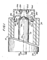
- Figs. 1-6 illustrate an exemplary embodiment of a multitarget x-ray tube 10 in accordance with the invention.
- Tube 10 generates four parallel, well collimated x-ray beams which have different characteristics and exhibit little cross-talk.
- the four x-ray beams can be turned on and off in any desired sequence or pattern.
- X-ray tube 10 comprises a round target support 12 which has a multifaceted front end with a number of targets 14a-14d thereon.
- the front end of target support 12 is generally pyramidal in shape, but the bases of the generally triangular sides of the pyramid are curved, the tip of the pyramid is replaced by an axial bore and the pyramid has channels separating its sides.
- Target support 12 is made of a material such as copper which is a good thermal and electrical conductor.
- Each of targets 14a-14d has a differently oriented x-ray emitting surface and can be made of a different x-ray emitting material.
- the four targets 14a-14d are made of titanium, palladium, platinum and copper, respectively.
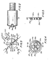
- Each of targets 14a-14d has a respective, individually controlled electron source, in the form of an electron gun 16a-16d, and each gun has a respective filament 18a-18d.
- Each of guns 16a-16d when energized emits a respective electron beam 20a-20d which, due to the potential difference between the gun and target and the tube geometry, impinges on the respective one of targets 14a-14d to cause x-ray emission therefrom.
- a front housing 22 encloses the front end of target support 12 and electron guns 14a-14d, and is connected to a main, larger housing 24 which in a known manner mechanically supports the previously described components and serves as a heat sink (and can have a non-circulating or a circulating oil bath) and has HV connectors 26 and filament connectors 28 at its back end.
- HV connectors 26 supply high voltage to target support 12 (and hence to targets 14a-14d) and to each of electron guns 14a-14d to establish in a known manner a potential difference between each gun and its target which is sufficient to generate the respective electron beams 20a-20d when the respective filaments 18a-18d are energized.
- Filament connectors 28 provide operating current to filaments 18a-18d. It is important to note that there are separate, individually controlled connections to the respective filaments so that any one or more filaments can be on or off at any one time.
- targets 14a-14d When energized by their respective electron beams 20a-20d, targets 14a-14d emit respective x-ray beams 30a-30d which are taken out through respective end windows 32a-32d in front housing 22.
- Cross-talk is reduced by providing tubular internal collimators 34a-34d through which the respective x-ray beams 30a-30d pass on their way to the respective end windows 32a-32d.
- the geometry of the targets, the collimators and the windows is such that x-ray beams 30a-30d are substantially parallel to each other and to axis 12a of target support 12.
- the sides of the pyramid at the front end of target support 12 are separated from each other by channels 36a-36d and the pyramid has an axial depression or bore 38 at its front end which is deeper than said channel.
- Targets 14a-14d cover the facets of the front end of the pyramid and each target extends partway into two adjacent ones of channels 36a-36d and into axial bore 38 but the targets remain spaced from each other.
- each of the x-ray targets can be a thin plate secured to the respective side of the pyramidal front end of target holder 12, for example by brazing.
- each target is bent over to extend partway into each adjacent channel, for example to (or close to) the bottom of the channel, and that the outside edges of each channel are rounded, as illustated at 36a1 and 36a2 for channel 36a.
- the outside edge of axial bore 38 is similarly rounded, as are the corners where the outside edges of the bore and the channels meet, and that the outside edge of bore 38 is not continuous but is made of the arcs which are between converging outside edges of adjacent channels.
- the dimensions of an exemplary embodiment of the target support and its faces, channels and bore are shown in Figs.
- target support 12 is round and has a diameter of about 0.75", the axial extent of its front end is about 0.10", the channels are about 0.10" deep and wide, the axial depression is about 0.25" deep and about 0.25" in diameter.
- the target material extends about 0.10" or slightly less into the channels and the axial bore.
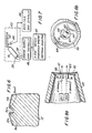
- the thickness of targets 14a and 14b is exaggerated in Fig. 6. In fact, the target thickness is of the order of 10 mils and there is a minimum required thickness, which is about 2 mils for typical target materials. If the target is of the same material as target support 12, a target plate may be brazed on or the appropriate facet of the target support front end may be appropriately finished so that its surface would serve as a target.
- the following materials are believed suitable for use as targets: Ti, Cr, Fe, Co, Ni, Cu, Mo, Rh, Ag, Ta, W, Re, Pt and Au. Which materials are selected for a particular x-ray tube and in what order they are arranged on the facets of the target support, depends primarily on the intended use of the x-ray tube.
- An x-ray tube made in accordance with the invention can be used, for example in an x-ray fluorescence spectrometer such as the earlier-identified units made by Link Analytical, to replace an x-ray tube of the type currently used therein.
- x-ray tube 10 of the type discussed in connection with Figs. 1-6 is oriented such that its x-ray beams 30a-30d impinge on a sample of material under analysis which is on a rotatable sample tray 40 in a housing 42.
- the x-rays emitted from the sample in response to the impingement thereon of x-rays from tube 10 are detected at a detector 44 whose output is analyzed and the results are displayed at an analyzer and display unit 46.
- Power is supplied to x-ray tube 10 from a power supply and control unit 48 through HV connectors 26 and filament connectors 28 in a manner which allows the on and off state of each of x-ray beams 30a-30d to be individually controlled.
- a unit 50 designated x-ray beam sequence and/or pattern selector, can operate under manual control, such as a selector knob or a keyboard, to provide unit 48 with control signals determining which of x-ray beams 30a-30d will be on and which will be off at any particular time. Alternately, these control signals can be generated as a programmed sequence under the control of the computer which is typically included in an analyzer of the kind identified above.
- a sample is brought in position by suitably rotating sample tray 40 and x-ray tube 10 is energized under the control of units 48 and 50 to generate a selected pattern and/or sequence of x-ray beams of different characteristics from its different targets.
- the collimated x-ray beams 30a-30d impinge on the target sample, which in response generates x-rays which have characteristics which depend in part on the nature of the impinging x-rays and in part on the nature of the sample material.
- the x-rays emitted from the sample are analyzed in a known manner and the results can be displayed or otherwise utilized in a known manner.
- the four x-ray beams from tube 10 can be all on at the same time, or can be turned on one at a time in any desired sequence, or can be turned on in any desired pattern of less than all four beams, or in any desired sequence of patterns or of patterns and single beams.
- the four x-ray beams can be parallel to each other and to the target support axis, as described above, or the geometry can be changed appropriately such that the four beams are at an angle to each other and/or the target support axis, for example such that they converge at the sample being analyzed.
- x-ray targets 61-64 are at the inside surface of x-ray window 66, facing the inside of a suitable vacuum housing 69.
- Window 66 is supported at the center of a target support 70 which in turn is affixed to the front end of housing 68.
- Targets 61-64 can but need not be made of different materials and can be formed on the inside surface of window 66 by a process such as sputtering.
- There is a separate, individually controlled electron source for each of targets 61-64 (only sources ES1 and ES2, for targets 61 and 62 are visible in Fig. 8a).
- Each source emits a respective electron beam which travels to its respective target along a direction substantially perpendicular to the plane of the target, as illustrated in Fig. 8a for the electron beams to targets 61 and 62.
- Each electron beam causes its target to emit an x-ray flux which exits housing 68 by passing through the outside surface of window 66 in a direction generally following the direction of the impinging electron beam, as is illustrated in Fig. 8a for the x-rays from targets 61 and 62.
- the tube includes a respective collimator for each target. As illustrated in Fig.
- each collimator is tubular, surrounds its target and extends therefrom toward the interior of housing 68.
- external collimators can be provided as well which can be in the form of tubes of x-ray attenuating material which surround the respective projection of the targets on the outside surface of window 66 and extend away from housing 68, to reduce cross talk and/or shape the x-rays from the respective targets in a known manner. It is noted that while Figs.
- FIGS. 8a and 8b illustrate the use of a single x-ray window, two or more separate, spaced apart windows can be used instead, one window per target or for a subset of two or more targets, and the number of targets can be more or less than four.
- the tube illustrated in Figs. 8a and 8b can be operated by simultaneously energizing all targets or any desired subset of the targets, or by energizing the targets in any desired sequence or pattern.
- a tube in accordance with the invention can have 5, 6, 7, 8, ... facets at the target support front end and an equal or lesser number of targets.
- the targets can be all of different materials or some targets may be made of the same material.
- the facets can be symmetrically or asymmetrically arranged relative to the target support axis, and can be the same or different in size.
- the geometry can be changed such that some or all of the x-ray beams are not parallel to each other and the directions of any one or more beams either converge or diverge relative to the directions of other beams, for example by changing the relative orientation of facets and the positions of the internal collimators and the windows.
- the electron guns can be as described above, where each filament is centered on its target and the electron beam impinges substantially on the entire target, in a pattern determined primarily by the geometry of the gun and the target, by their relative positions and by the potential between the target and the gun.
- additional fields can be used in a known manner to focus one or more of the electron beams on their respective targets, as with plates 52 and focusing field potential sources E(f) schematically illustrated for the electrons from filament 18a in Fig. 3. While filaments have been discussed as electron sources, any other suitable hot or cold cathodes can be used. While one use of the invented x-ray tube is in x-ray fluorescence spectrometers, the tube can be used in other environments as well, such as, without limitation, for thickness gauging by use of x-ray transmission measurements, for process control and material specification control, for radiography or densitometry, and as an isotope replacement. As will be appreciated by those skilled in the art, many other variations are possible within the scope of the invention.
Landscapes
- X-Ray Techniques (AREA)
- Analysing Materials By The Use Of Radiation (AREA)
Applications Claiming Priority (2)
| Application Number | Priority Date | Filing Date | Title |
|---|---|---|---|
| US263069 | 1988-10-25 | ||
| US07/263,069 US4870671A (en) | 1988-10-25 | 1988-10-25 | Multitarget x-ray tube |
Publications (1)
| Publication Number | Publication Date |
|---|---|
| EP0366372A1 true EP0366372A1 (de) | 1990-05-02 |
Family
ID=23000260
Family Applications (1)
| Application Number | Title | Priority Date | Filing Date |
|---|---|---|---|
| EP89310822A Withdrawn EP0366372A1 (de) | 1988-10-25 | 1989-10-20 | Röntgenröhre mit Mehrfachtarget |
Country Status (3)
| Country | Link |
|---|---|
| US (1) | US4870671A (de) |
| EP (1) | EP0366372A1 (de) |
| JP (1) | JPH02170335A (de) |
Cited By (5)
| Publication number | Priority date | Publication date | Assignee | Title |
|---|---|---|---|---|
| GB2333681B (en) * | 1998-01-24 | 2002-10-09 | Heimann Systems Gmbh & Co | X-ray generator |
| FR2833751A1 (fr) * | 2001-12-18 | 2003-06-20 | Thales Sa | Generateur de rayons x a rayonnement focalise |
| RU2257638C1 (ru) * | 2004-06-17 | 2005-07-27 | Кузнецов Вадим Львович | Рентгеновская трубка (варианты) |
| EP1418610B1 (de) * | 2002-11-06 | 2005-10-19 | Feinfocus Gmbh | Mikrofocus-Röntgenröhre |
| RU2399907C1 (ru) * | 2008-02-28 | 2010-09-20 | Кэнон Кабусики Кайся | Устройство генерирования множества рентгеновских лучей и устройство формирования рентгеновского изображения |
Families Citing this family (43)
| Publication number | Priority date | Publication date | Assignee | Title |
|---|---|---|---|---|
| NL9000203A (nl) * | 1990-01-29 | 1991-08-16 | Philips Nv | Eindvenster roentgenbuis. |
| FR2658002B1 (fr) * | 1990-02-02 | 1992-05-22 | Gen Electric Cgr | Cathode a deflexion en diedre pour tube a rayons x. |
| EP0603448B1 (de) * | 1992-12-23 | 1998-08-26 | GRETAG Aktiengesellschaft | Handdensitometer |
| US5428657A (en) * | 1994-03-22 | 1995-06-27 | Georgia Tech Research Corporation | X-ray monitoring system |
| AUPQ831200A0 (en) * | 2000-06-22 | 2000-07-13 | X-Ray Technologies Pty Ltd | X-ray micro-target source |
| US7180981B2 (en) | 2002-04-08 | 2007-02-20 | Nanodynamics-88, Inc. | High quantum energy efficiency X-ray tube and targets |
| US7274772B2 (en) * | 2004-05-27 | 2007-09-25 | Cabot Microelectronics Corporation | X-ray source with nonparallel geometry |
| US7396160B2 (en) * | 2004-07-30 | 2008-07-08 | Neurologica Corp. | Computerized tomography (CT) imaging system with monoblock X-ray tube assembly |
| US7568836B2 (en) * | 2004-07-30 | 2009-08-04 | Neurologica Corp. | Mobile computerized tomography (CT) imaging system with off-center x-ray beam |
| US7248672B2 (en) * | 2005-04-21 | 2007-07-24 | Bruker Axs, Inc. | Multiple-position x-ray tube for diffractometer |
| JP4878311B2 (ja) * | 2006-03-03 | 2012-02-15 | キヤノン株式会社 | マルチx線発生装置 |
| JP5436760B2 (ja) * | 2007-05-21 | 2014-03-05 | 石黒 義久 | X線管 |
| US7593509B2 (en) * | 2007-09-27 | 2009-09-22 | Varian Medical Systems, Inc. | Analytical x-ray tube for close coupled sample analysis |
| US8736138B2 (en) | 2007-09-28 | 2014-05-27 | Brigham Young University | Carbon nanotube MEMS assembly |
| US9305735B2 (en) | 2007-09-28 | 2016-04-05 | Brigham Young University | Reinforced polymer x-ray window |
| US8498381B2 (en) | 2010-10-07 | 2013-07-30 | Moxtek, Inc. | Polymer layer on X-ray window |
| US8081734B2 (en) * | 2008-12-02 | 2011-12-20 | The United States Of America As Represented By The Administrator Of The National Aeronautics And Space Administration | Miniature, low-power X-ray tube using a microchannel electron generator electron source |
| DE102009012325A1 (de) * | 2009-03-09 | 2010-09-30 | Siemens Aktiengesellschaft | Anode |
| US8247971B1 (en) | 2009-03-19 | 2012-08-21 | Moxtek, Inc. | Resistively heated small planar filament |
| US7983394B2 (en) | 2009-12-17 | 2011-07-19 | Moxtek, Inc. | Multiple wavelength X-ray source |
| US8995621B2 (en) | 2010-09-24 | 2015-03-31 | Moxtek, Inc. | Compact X-ray source |
| US8526574B2 (en) | 2010-09-24 | 2013-09-03 | Moxtek, Inc. | Capacitor AC power coupling across high DC voltage differential |
| US8804910B1 (en) | 2011-01-24 | 2014-08-12 | Moxtek, Inc. | Reduced power consumption X-ray source |
| US8750458B1 (en) | 2011-02-17 | 2014-06-10 | Moxtek, Inc. | Cold electron number amplifier |
| US8929515B2 (en) | 2011-02-23 | 2015-01-06 | Moxtek, Inc. | Multiple-size support for X-ray window |
| US8792619B2 (en) | 2011-03-30 | 2014-07-29 | Moxtek, Inc. | X-ray tube with semiconductor coating |
| US9076628B2 (en) | 2011-05-16 | 2015-07-07 | Brigham Young University | Variable radius taper x-ray window support structure |
| US8989354B2 (en) | 2011-05-16 | 2015-03-24 | Brigham Young University | Carbon composite support structure |
| US9174412B2 (en) | 2011-05-16 | 2015-11-03 | Brigham Young University | High strength carbon fiber composite wafers for microfabrication |
| US8817950B2 (en) | 2011-12-22 | 2014-08-26 | Moxtek, Inc. | X-ray tube to power supply connector |
| US8761344B2 (en) | 2011-12-29 | 2014-06-24 | Moxtek, Inc. | Small x-ray tube with electron beam control optics |
| US9072154B2 (en) | 2012-12-21 | 2015-06-30 | Moxtek, Inc. | Grid voltage generation for x-ray tube |
| US9184020B2 (en) | 2013-03-04 | 2015-11-10 | Moxtek, Inc. | Tiltable or deflectable anode x-ray tube |
| US9177755B2 (en) | 2013-03-04 | 2015-11-03 | Moxtek, Inc. | Multi-target X-ray tube with stationary electron beam position |
| US9173623B2 (en) | 2013-04-19 | 2015-11-03 | Samuel Soonho Lee | X-ray tube and receiver inside mouth |
| WO2015164968A1 (en) | 2014-04-29 | 2015-11-05 | Dana Canada Corporation | Charge air cooler with multi-piece plastic housing |
| US20170194124A1 (en) * | 2016-01-06 | 2017-07-06 | Varian Medical Systems | X-ray delivery |
| DE102017127372A1 (de) | 2017-11-21 | 2019-05-23 | Smiths Heimann Gmbh | Anodenkopf für Röntgenstrahlenerzeuger |
| US10748735B2 (en) | 2018-03-29 | 2020-08-18 | The Boeing Company | Multi-spectral X-ray target and source |
| US11545332B1 (en) * | 2019-08-22 | 2023-01-03 | Varex Imaging Corporation | Anode shield |
| US11257653B2 (en) * | 2020-03-27 | 2022-02-22 | The Boeing Company | Integrated aperture shield for x-ray tubes |
| US11169098B2 (en) | 2020-04-02 | 2021-11-09 | The Boeing Company | System, method, and apparatus for x-ray backscatter inspection of parts |
| US12163903B2 (en) | 2021-05-12 | 2024-12-10 | The Boeing Company | System, method, and apparatus for x-ray backscatter inspection of parts |
Citations (4)
| Publication number | Priority date | Publication date | Assignee | Title |
|---|---|---|---|---|
| US2160605A (en) * | 1936-12-18 | 1939-05-30 | Gen Electric | Regulating system |
| DE2749856A1 (de) * | 1977-11-08 | 1979-05-10 | Leybold Heraeus Gmbh & Co Kg | Roentgenroehre |
| GB2133208A (en) * | 1982-11-18 | 1984-07-18 | Kratos Ltd | X-ray sources |
| GB2212975A (en) * | 1987-11-30 | 1989-08-02 | Rigaku Denki Kabushiki Kaisha | Rotating anode X-ray tube |
Family Cites Families (3)
| Publication number | Priority date | Publication date | Assignee | Title |
|---|---|---|---|---|
| US4007375A (en) * | 1975-07-14 | 1977-02-08 | Albert Richard D | Multi-target X-ray source |
| US4017757A (en) * | 1976-01-02 | 1977-04-12 | The Machlett Laboratories, Incorporated | Multi-target X-ray tube |
| FR2415876A1 (fr) * | 1978-01-27 | 1979-08-24 | Radiologie Cie Gle | Tube a rayons x, notamment pour tomodensitometre |
-
1988
- 1988-10-25 US US07/263,069 patent/US4870671A/en not_active Expired - Fee Related
-
1989
- 1989-10-20 EP EP89310822A patent/EP0366372A1/de not_active Withdrawn
- 1989-10-23 JP JP1273929A patent/JPH02170335A/ja active Pending
Patent Citations (4)
| Publication number | Priority date | Publication date | Assignee | Title |
|---|---|---|---|---|
| US2160605A (en) * | 1936-12-18 | 1939-05-30 | Gen Electric | Regulating system |
| DE2749856A1 (de) * | 1977-11-08 | 1979-05-10 | Leybold Heraeus Gmbh & Co Kg | Roentgenroehre |
| GB2133208A (en) * | 1982-11-18 | 1984-07-18 | Kratos Ltd | X-ray sources |
| GB2212975A (en) * | 1987-11-30 | 1989-08-02 | Rigaku Denki Kabushiki Kaisha | Rotating anode X-ray tube |
Cited By (9)
| Publication number | Priority date | Publication date | Assignee | Title |
|---|---|---|---|---|
| GB2333681B (en) * | 1998-01-24 | 2002-10-09 | Heimann Systems Gmbh & Co | X-ray generator |
| FR2833751A1 (fr) * | 2001-12-18 | 2003-06-20 | Thales Sa | Generateur de rayons x a rayonnement focalise |
| WO2003052789A1 (fr) * | 2001-12-18 | 2003-06-26 | Thales | Generateur de rayons x a rayonnement focalise |
| EP1418610B1 (de) * | 2002-11-06 | 2005-10-19 | Feinfocus Gmbh | Mikrofocus-Röntgenröhre |
| RU2257638C1 (ru) * | 2004-06-17 | 2005-07-27 | Кузнецов Вадим Львович | Рентгеновская трубка (варианты) |
| RU2399907C1 (ru) * | 2008-02-28 | 2010-09-20 | Кэнон Кабусики Кайся | Устройство генерирования множества рентгеновских лучей и устройство формирования рентгеновского изображения |
| US7991120B2 (en) | 2008-02-28 | 2011-08-02 | Canon Kabushiki Kaisha | Multi X-ray generating apparatus and X-ray imaging apparatus |
| US8422637B2 (en) | 2008-02-28 | 2013-04-16 | Canon Kabushiki Kaisha | Multi X-ray generating apparatus and X-ray imaging apparatus |
| US8666024B2 (en) | 2008-02-28 | 2014-03-04 | Canon Kabushiki Kaisha | Multi-X-ray generating apparatus and X-ray imaging apparatus |
Also Published As
| Publication number | Publication date |
|---|---|
| US4870671A (en) | 1989-09-26 |
| JPH02170335A (ja) | 1990-07-02 |
Similar Documents
| Publication | Publication Date | Title |
|---|---|---|
| US4870671A (en) | Multitarget x-ray tube | |
| US3983397A (en) | Selectable wavelength X-ray source | |
| US4260885A (en) | Selectable wavelength X-ray source, spectrometer and assay method | |
| US4048496A (en) | Selectable wavelength X-ray source, spectrometer and assay method | |
| EP2430638B1 (de) | Röntgenquelle mit mehreren elektronenemittern und verfahren damit | |
| US6438207B1 (en) | X-ray tube having improved focal spot control | |
| Loretto | Electron beam analysis of materials | |
| US6661876B2 (en) | Mobile miniature X-ray source | |
| US7317784B2 (en) | Multiple wavelength X-ray source | |
| US6333968B1 (en) | Transmission cathode for X-ray production | |
| US5940469A (en) | Multi-chromatic x-ray source | |
| US3714486A (en) | Field emission x-ray tube | |
| US7809113B2 (en) | X-ray source and fluorescent X-ray analyzing apparatus | |
| US4689809A (en) | X-ray tube having an adjustable focal spot | |
| US6141400A (en) | X-ray source which emits fluorescent X-rays | |
| US20060233307A1 (en) | X-ray source for materials analysis systems | |
| KR20070114741A (ko) | X-선 소스용 자성 헤드 | |
| GB2333681A (en) | Dual voltage X-ray generator | |
| GB2133208A (en) | X-ray sources | |
| HU177322B (en) | X-ray tube form emitting cone of rays with plain form,fan-shape and wide corner angle | |
| US9508523B2 (en) | Forward flux channel X-ray source | |
| US8081734B2 (en) | Miniature, low-power X-ray tube using a microchannel electron generator electron source | |
| JPH09180894A (ja) | X線源 | |
| CA2241640A1 (en) | X-ray fluorescence measuring system making use of polarized excitation radiation, and x-ray tube | |
| US20050117705A1 (en) | Device and method for producing a spatially uniformly intense source of x-rays |
Legal Events
| Date | Code | Title | Description |
|---|---|---|---|
| PUAI | Public reference made under article 153(3) epc to a published international application that has entered the european phase |
Free format text: ORIGINAL CODE: 0009012 |
|
| AK | Designated contracting states |
Kind code of ref document: A1 Designated state(s): DE FR GB |
|
| 17P | Request for examination filed |
Effective date: 19900820 |
|
| 17Q | First examination report despatched |
Effective date: 19921202 |
|
| STAA | Information on the status of an ep patent application or granted ep patent |
Free format text: STATUS: THE APPLICATION IS DEEMED TO BE WITHDRAWN |
|
| 18D | Application deemed to be withdrawn |
Effective date: 19930615 |