EP0366347B1 - Improvements in mechanical pumps - Google Patents
Improvements in mechanical pumps Download PDFInfo
- Publication number
- EP0366347B1 EP0366347B1 EP89310702A EP89310702A EP0366347B1 EP 0366347 B1 EP0366347 B1 EP 0366347B1 EP 89310702 A EP89310702 A EP 89310702A EP 89310702 A EP89310702 A EP 89310702A EP 0366347 B1 EP0366347 B1 EP 0366347B1
- Authority
- EP
- European Patent Office
- Prior art keywords
- rotor
- cavity
- rotors
- outlet
- pump
- Prior art date
- Legal status (The legal status is an assumption and is not a legal conclusion. Google has not performed a legal analysis and makes no representation as to the accuracy of the status listed.)
- Expired - Lifetime
Links
Images
Classifications
-
- F—MECHANICAL ENGINEERING; LIGHTING; HEATING; WEAPONS; BLASTING
- F04—POSITIVE - DISPLACEMENT MACHINES FOR LIQUIDS; PUMPS FOR LIQUIDS OR ELASTIC FLUIDS
- F04C—ROTARY-PISTON, OR OSCILLATING-PISTON, POSITIVE-DISPLACEMENT MACHINES FOR LIQUIDS; ROTARY-PISTON, OR OSCILLATING-PISTON, POSITIVE-DISPLACEMENT PUMPS
- F04C18/00—Rotary-piston pumps specially adapted for elastic fluids
- F04C18/08—Rotary-piston pumps specially adapted for elastic fluids of intermeshing-engagement type, i.e. with engagement of co-operating members similar to that of toothed gearing
- F04C18/12—Rotary-piston pumps specially adapted for elastic fluids of intermeshing-engagement type, i.e. with engagement of co-operating members similar to that of toothed gearing of other than internal-axis type
- F04C18/123—Rotary-piston pumps specially adapted for elastic fluids of intermeshing-engagement type, i.e. with engagement of co-operating members similar to that of toothed gearing of other than internal-axis type with radially or approximately radially from the rotor body extending tooth-like elements, co-operating with recesses in the other rotor, e.g. one tooth
-
- F—MECHANICAL ENGINEERING; LIGHTING; HEATING; WEAPONS; BLASTING
- F04—POSITIVE - DISPLACEMENT MACHINES FOR LIQUIDS; PUMPS FOR LIQUIDS OR ELASTIC FLUIDS
- F04C—ROTARY-PISTON, OR OSCILLATING-PISTON, POSITIVE-DISPLACEMENT MACHINES FOR LIQUIDS; ROTARY-PISTON, OR OSCILLATING-PISTON, POSITIVE-DISPLACEMENT PUMPS
- F04C18/00—Rotary-piston pumps specially adapted for elastic fluids
- F04C18/08—Rotary-piston pumps specially adapted for elastic fluids of intermeshing-engagement type, i.e. with engagement of co-operating members similar to that of toothed gearing
- F04C18/082—Details specially related to intermeshing engagement type pumps
- F04C18/088—Elements in the toothed wheels or the carter for relieving the pressure of fluid imprisoned in the zones of engagement
Definitions
- the present invention relates to mechanical pumps and in particular to mechanical vacuum pumps incorporating at least one pair of intermeshing rotors, especially rotors of the type known as "claw" rotors.
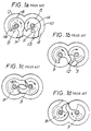
- FIG. 1a to 1d of the accompanying drawings shows a pair of rotors 5,8 mounted on respective shafts 1A,1B for rotation about the shafts in the direction shown by the arrows with the claws 7,13 closely engaging the walls of a chamber 2.
- the claws scoop the liquid as they rotate, and the claw 7 of the rotor 8 which is associated with the inlet port 9 throws the liquid towards the outlet port 3 as it rotates from the positions 1a through 1b to 1c of Figure 1.
- the present invention is concerned with the provision a mechanical pump having at least one pair of intermeshing rotors in which any hydraulic hammering effect can be mitigated or prevented by providing a cavity in a leading edge of a rotor to retain the liquid during critical parts of the pump cycle.
- a mechanical pump comprising first and second intermeshing rotors (5, 8), each rotor being mounted for rotation on respective shafts (1A, 1B) and located in a pumping chamber (2), an inlet (9) to the pumping chamber with which the first rotor is associated and an outlet (3) from the pumping chamber with which the second rotor (5) is associated, a cavity (6) being present in the surface of the second rotor (5) adjacent the outlet (3) which cavity (6) communicates with the outlet during each revolution of the second rotor, and the cavity being substantially cup-shaped, characterised in that the cavity extends in a radial direction and is positioned such that, in use of the pump, liquid present in the chamber is urged into, and retained within, the cavity during rotation of the second rotor and is ejected therefrom by centrifugal forces during communication between the cavity and outlet.
- the invention is primarily, but not exclusively, concerned with pumps having a "claw" type rotor profile.
- the nature of the cavity must be such that any condensed liquid which is present in particular in the volume of gas or vapour being "swept" by the rotors is urged into the cavity and ejected therefrom when the swept volume communicates with the chamber outlet.
- the pump is one in which the inlet to the pumping chamber is formed as a port in a first wall of the pumping chamber and the outlet from the pumping chamber is formed as a port in an opposite wall of the pumping chamber.
- the cavity is positioned in a side of the second rotor which engages the wall of the chamber containing the outlet.
- the position of the cavity is such that the condensed liquid is urged into the cavity by centrifugal force.
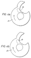
- the shape of the cavity is not important but preferably the shape is such that condensed liquid is retained within the cavity despite the rotation of the rotor and the centrifugal forces caused thereby. This can be achieved, for example, by arranging for the cavity to be substantially cup-shaped and extending in a direction such that centrifugally driven liquid is urged to the base of the cup before being deposited in the chamber outlet.
- the pump may comprise a plurality of individual chambers each having its own pair of rotors, some or, preferably, all of which may have cavities in accordance with the invention.
- the shafts on which the rotors are mounted it is generally preferable for the shafts on which the rotors are mounted to be orientated vertically. It is also preferable for the inlet to be positioned in a wall in the top of the chamber and for the outlet to be positioned in a wall at the bottom of the chamber.
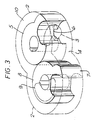
- the pumping chamber 10 of a mechanical pump contains intermeshing claw type rotors 5, 8 each mounted on a shaft (not shown) in a manner known per se .
- the rotor 5 rotates in a clockwise sense as indicated by the arrows whilst rotor 8 rotates in an anti-clockwise sense.
- said liquid When used to pump a vapour which during the pumping operation condenses to a liquid, said liquid will be trapped in the space 12 between the rotors 5, 8at a time when the outlet port 3 is closed. As a consequence, the liquid can create a hammering effect between the rotors 5, 8 which can lead to mechanical failure.
- the rotor 5 which is associated with the outlet port 3 is formed with a cavity 6 on its surface immediately adjacent the side wall 4 in which the outlet port 3 is formed.
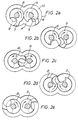
- the shape and location of the cavity 6 and its relation to the outlet port 3 is illustrated in Figures 2a to 2e and Figure 3.
- a cavity 6 is provided in the rotor face associated with the outlet port at each stage. In all cases, the position of the cavity is such that it does not interfere with the basic operation of the pump.
Landscapes
- Engineering & Computer Science (AREA)
- Mechanical Engineering (AREA)
- General Engineering & Computer Science (AREA)
- Rotary Pumps (AREA)
- Applications Or Details Of Rotary Compressors (AREA)
- Structures Of Non-Positive Displacement Pumps (AREA)
Applications Claiming Priority (2)
| Application Number | Priority Date | Filing Date | Title |
|---|---|---|---|
| GB8825284 | 1988-10-28 | ||
| GB888825284A GB8825284D0 (en) | 1988-10-28 | 1988-10-28 | Improvements in mechanical pumps |
Publications (3)
| Publication Number | Publication Date |
|---|---|
| EP0366347A2 EP0366347A2 (en) | 1990-05-02 |
| EP0366347A3 EP0366347A3 (en) | 1990-08-16 |
| EP0366347B1 true EP0366347B1 (en) | 1993-07-07 |
Family
ID=10645948
Family Applications (1)
| Application Number | Title | Priority Date | Filing Date |
|---|---|---|---|
| EP89310702A Expired - Lifetime EP0366347B1 (en) | 1988-10-28 | 1989-10-18 | Improvements in mechanical pumps |
Country Status (6)
| Country | Link |
|---|---|
| US (1) | US5055017A (es) |
| EP (1) | EP0366347B1 (es) |
| JP (1) | JP3029202B2 (es) |
| DE (1) | DE68907465T2 (es) |
| ES (1) | ES2042004T3 (es) |
| GB (1) | GB8825284D0 (es) |
Families Citing this family (8)
| Publication number | Priority date | Publication date | Assignee | Title |
|---|---|---|---|---|
| DE4233142A1 (de) * | 1992-10-02 | 1994-04-07 | Leybold Ag | Verfahren zum Betrieb einer Klauenvakuumpumpe und für die Durchführung dieses Betriebsverfahrens geeignete Klauenvakuumpumpe |
| DE19629174A1 (de) * | 1996-07-19 | 1998-01-22 | Leybold Vakuum Gmbh | Klauenvakuumpumpe |
| GB2426036A (en) * | 2005-05-10 | 2006-11-15 | Bernard Whicher | Vertical Northey compressor |
| RU2282063C1 (ru) * | 2005-09-01 | 2006-08-20 | Виктор Павлович Шлапацкий | Роторная машина |
| US20070172790A1 (en) * | 2006-01-26 | 2007-07-26 | Midmark Corporation | Dental Vacuum System |
| CN104929942B (zh) * | 2015-07-09 | 2016-10-05 | 中国石油大学(华东) | 一种全啮合的爪式转子型线 |
| CN108050061B (zh) * | 2018-01-09 | 2023-08-29 | 中国石油大学(华东) | 一种高效爪式转子 |
| CN113446065A (zh) * | 2020-03-27 | 2021-09-28 | 信强(宁波)半导体设备制造有限公司 | 爪形转子以及真空马达转子组合 |
Family Cites Families (7)
| Publication number | Priority date | Publication date | Assignee | Title |
|---|---|---|---|---|
| US2058817A (en) * | 1931-12-22 | 1936-10-27 | Northey Rotary Engines Ltd | Rotary internal combustion engine |
| US2097037A (en) * | 1933-08-25 | 1937-10-26 | Northey Rotary Engines Ltd | Rotary compressor or vacuum pump |
| US2289371A (en) * | 1938-03-01 | 1942-07-14 | Jarvis C Marble | Rotary screw apparatus |
| US3472445A (en) | 1968-04-08 | 1969-10-14 | Arthur E Brown | Rotary positive displacement machines |
| SE351012B (es) * | 1970-10-01 | 1972-11-13 | Atlas Copco Ab | |
| GB1335045A (en) * | 1970-10-17 | 1973-10-24 | Brown A E | Rotary displacement machines |
| US4504201A (en) * | 1982-11-22 | 1985-03-12 | The Boc Group Plc | Mechanical pumps |
-
1988
- 1988-10-28 GB GB888825284A patent/GB8825284D0/en active Pending
-
1989
- 1989-10-18 EP EP89310702A patent/EP0366347B1/en not_active Expired - Lifetime
- 1989-10-18 DE DE89310702T patent/DE68907465T2/de not_active Expired - Fee Related
- 1989-10-18 ES ES198989310702T patent/ES2042004T3/es not_active Expired - Lifetime
- 1989-10-23 US US07/425,650 patent/US5055017A/en not_active Expired - Lifetime
- 1989-10-26 JP JP1279602A patent/JP3029202B2/ja not_active Expired - Lifetime
Also Published As
| Publication number | Publication date |
|---|---|
| JP3029202B2 (ja) | 2000-04-04 |
| EP0366347A3 (en) | 1990-08-16 |
| DE68907465D1 (de) | 1993-08-12 |
| JPH02185683A (ja) | 1990-07-20 |
| US5055017A (en) | 1991-10-08 |
| GB8825284D0 (en) | 1988-11-30 |
| DE68907465T2 (de) | 1993-10-21 |
| EP0366347A2 (en) | 1990-05-02 |
| ES2042004T3 (es) | 1993-12-01 |
Similar Documents
| Publication | Publication Date | Title |
|---|---|---|
| EP0366347B1 (en) | Improvements in mechanical pumps | |
| EP0464970B1 (en) | Scroll type fluid machinery | |
| EP0168561B1 (en) | Scroll compressor | |
| KR100573752B1 (ko) | 압축 매질용 용적식 기계 | |
| EP2180188A1 (en) | Improvements in and relating to Roots pumps | |
| US7156922B2 (en) | Multi-chamber installation for treating objects under vacuum, method for evacuating said installation and evacuation system therefor | |
| EP0594461A1 (en) | Vacuum pumps | |
| US5697771A (en) | Vacuum pump with oil separator | |
| EP1130264B1 (en) | Compound vacuum pumps | |
| US6129534A (en) | Vacuum pumps | |
| KR100497982B1 (ko) | 루츠형 로터와 스크루형 로터를 지닌 복합 드라이 진공펌프 | |
| US5494412A (en) | Oil delivery prevention device for horizontal type rotary compressor | |
| US5044906A (en) | Screw rotor for screw pump device having negative torque on the female rotor | |
| US4295794A (en) | Selective mode multi-stage vacuum pump | |
| EP0679810A2 (en) | Scroll apparatus | |
| US5846066A (en) | Vacuum pumps with claw-type rotor and roots-type rotor near the outlet | |
| EP0172674B1 (en) | Scroll type fluid compressor | |
| US4943215A (en) | Multistage vacuum pump with bore for fouling removal | |
| JP3721587B2 (ja) | 密閉型電動圧縮機 | |
| KR100624982B1 (ko) | 복수 단의 루츠형 로터와 스크루형 로터를 지닌 복합드라이 진공 펌프 | |
| KR102759237B1 (ko) | 이형상의 로터로 구성된 다단형 건식 진공 펌프 | |
| KR102759236B1 (ko) | 파우더 수용부를 갖는 건식 진공 펌프용 케이싱 및 이를 포함하는 건식 진공 펌프 | |
| JPH01216092A (ja) | 真空ポンプ装置 | |
| JPH0431685A (ja) | 多段スクリュー式流体機械 | |
| EP1024290A1 (en) | Vacuum pump systems |
Legal Events
| Date | Code | Title | Description |
|---|---|---|---|
| PUAI | Public reference made under article 153(3) epc to a published international application that has entered the european phase |
Free format text: ORIGINAL CODE: 0009012 |
|
| AK | Designated contracting states |
Kind code of ref document: A2 Designated state(s): CH DE ES FR GB IT LI NL SE |
|
| PGFP | Annual fee paid to national office [announced via postgrant information from national office to epo] |
Ref country code: LU Payment date: 19900621 Year of fee payment: 4 |
|
| PUAL | Search report despatched |
Free format text: ORIGINAL CODE: 0009013 |
|
| AK | Designated contracting states |
Kind code of ref document: A3 Designated state(s): CH DE ES FR GB IT LI NL SE |
|
| 17P | Request for examination filed |
Effective date: 19901114 |
|
| 17Q | First examination report despatched |
Effective date: 19910829 |
|
| GRAA | (expected) grant |
Free format text: ORIGINAL CODE: 0009210 |
|
| ITF | It: translation for a ep patent filed | ||
| AK | Designated contracting states |
Kind code of ref document: B1 Designated state(s): CH DE ES FR GB IT LI NL SE |
|
| PG25 | Lapsed in a contracting state [announced via postgrant information from national office to epo] |
Ref country code: NL Effective date: 19930707 Ref country code: SE Effective date: 19930707 |
|
| ET | Fr: translation filed | ||
| REF | Corresponds to: |
Ref document number: 68907465 Country of ref document: DE Date of ref document: 19930812 |
|
| PGFP | Annual fee paid to national office [announced via postgrant information from national office to epo] |
Ref country code: SE Payment date: 19930921 Year of fee payment: 5 |
|
| PGFP | Annual fee paid to national office [announced via postgrant information from national office to epo] |
Ref country code: NL Payment date: 19931031 Year of fee payment: 5 |
|
| REG | Reference to a national code |
Ref country code: ES Ref legal event code: FG2A Ref document number: 2042004 Country of ref document: ES Kind code of ref document: T3 |
|
| NLV1 | Nl: lapsed or annulled due to failure to fulfill the requirements of art. 29p and 29m of the patents act | ||
| PLBE | No opposition filed within time limit |
Free format text: ORIGINAL CODE: 0009261 |
|
| STAA | Information on the status of an ep patent application or granted ep patent |
Free format text: STATUS: NO OPPOSITION FILED WITHIN TIME LIMIT |
|
| 26N | No opposition filed | ||
| PGFP | Annual fee paid to national office [announced via postgrant information from national office to epo] |
Ref country code: ES Payment date: 19941013 Year of fee payment: 6 |
|
| PG25 | Lapsed in a contracting state [announced via postgrant information from national office to epo] |
Ref country code: ES Free format text: LAPSE BECAUSE OF NON-PAYMENT OF DUE FEES Effective date: 19951019 |
|
| PGFP | Annual fee paid to national office [announced via postgrant information from national office to epo] |
Ref country code: CH Payment date: 19981019 Year of fee payment: 10 |
|
| REG | Reference to a national code |
Ref country code: ES Ref legal event code: FD2A Effective date: 19990503 |
|
| PG25 | Lapsed in a contracting state [announced via postgrant information from national office to epo] |
Ref country code: LI Free format text: LAPSE BECAUSE OF NON-PAYMENT OF DUE FEES Effective date: 19991031 Ref country code: CH Free format text: LAPSE BECAUSE OF NON-PAYMENT OF DUE FEES Effective date: 19991031 |
|
| REG | Reference to a national code |
Ref country code: CH Ref legal event code: PL |
|
| REG | Reference to a national code |
Ref country code: GB Ref legal event code: IF02 |
|
| PG25 | Lapsed in a contracting state [announced via postgrant information from national office to epo] |
Ref country code: IT Free format text: LAPSE BECAUSE OF NON-PAYMENT OF DUE FEES Effective date: 20051018 |
|
| REG | Reference to a national code |
Ref country code: GB Ref legal event code: 732E |
|
| PGFP | Annual fee paid to national office [announced via postgrant information from national office to epo] |
Ref country code: DE Payment date: 20071130 Year of fee payment: 19 |
|
| REG | Reference to a national code |
Ref country code: FR Ref legal event code: TP |
|
| PGFP | Annual fee paid to national office [announced via postgrant information from national office to epo] |
Ref country code: FR Payment date: 20071017 Year of fee payment: 19 Ref country code: GB Payment date: 20071029 Year of fee payment: 19 |
|
| GBPC | Gb: european patent ceased through non-payment of renewal fee |
Effective date: 20081018 |
|
| REG | Reference to a national code |
Ref country code: FR Ref legal event code: ST Effective date: 20090630 |
|
| PG25 | Lapsed in a contracting state [announced via postgrant information from national office to epo] |
Ref country code: DE Free format text: LAPSE BECAUSE OF NON-PAYMENT OF DUE FEES Effective date: 20090501 |
|
| PG25 | Lapsed in a contracting state [announced via postgrant information from national office to epo] |
Ref country code: FR Free format text: LAPSE BECAUSE OF NON-PAYMENT OF DUE FEES Effective date: 20081031 |
|
| PG25 | Lapsed in a contracting state [announced via postgrant information from national office to epo] |
Ref country code: GB Free format text: LAPSE BECAUSE OF NON-PAYMENT OF DUE FEES Effective date: 20081018 |