EP0366347A2 - Improvements in mechanical pumps - Google Patents
Improvements in mechanical pumps Download PDFInfo
- Publication number
- EP0366347A2 EP0366347A2 EP89310702A EP89310702A EP0366347A2 EP 0366347 A2 EP0366347 A2 EP 0366347A2 EP 89310702 A EP89310702 A EP 89310702A EP 89310702 A EP89310702 A EP 89310702A EP 0366347 A2 EP0366347 A2 EP 0366347A2
- Authority
- EP
- European Patent Office
- Prior art keywords
- rotor
- pumping chamber
- rotors
- outlet
- cavity
- Prior art date
- Legal status (The legal status is an assumption and is not a legal conclusion. Google has not performed a legal analysis and makes no representation as to the accuracy of the status listed.)
- Granted
Links
- 238000005086 pumping Methods 0.000 claims abstract description 29
- 210000000078 claw Anatomy 0.000 claims abstract description 15
- 239000007788 liquid Substances 0.000 description 19
- 230000000694 effects Effects 0.000 description 6
- 239000007789 gas Substances 0.000 description 4
- 238000007906 compression Methods 0.000 description 1
- 230000005484 gravity Effects 0.000 description 1
- 230000000717 retained effect Effects 0.000 description 1
Images
Classifications
-
- F—MECHANICAL ENGINEERING; LIGHTING; HEATING; WEAPONS; BLASTING
- F04—POSITIVE - DISPLACEMENT MACHINES FOR LIQUIDS; PUMPS FOR LIQUIDS OR ELASTIC FLUIDS
- F04C—ROTARY-PISTON, OR OSCILLATING-PISTON, POSITIVE-DISPLACEMENT MACHINES FOR LIQUIDS; ROTARY-PISTON, OR OSCILLATING-PISTON, POSITIVE-DISPLACEMENT PUMPS
- F04C18/00—Rotary-piston pumps specially adapted for elastic fluids
- F04C18/08—Rotary-piston pumps specially adapted for elastic fluids of intermeshing-engagement type, i.e. with engagement of co-operating members similar to that of toothed gearing
- F04C18/12—Rotary-piston pumps specially adapted for elastic fluids of intermeshing-engagement type, i.e. with engagement of co-operating members similar to that of toothed gearing of other than internal-axis type
- F04C18/123—Rotary-piston pumps specially adapted for elastic fluids of intermeshing-engagement type, i.e. with engagement of co-operating members similar to that of toothed gearing of other than internal-axis type with radially or approximately radially from the rotor body extending tooth-like elements, co-operating with recesses in the other rotor, e.g. one tooth
-
- F—MECHANICAL ENGINEERING; LIGHTING; HEATING; WEAPONS; BLASTING
- F04—POSITIVE - DISPLACEMENT MACHINES FOR LIQUIDS; PUMPS FOR LIQUIDS OR ELASTIC FLUIDS
- F04C—ROTARY-PISTON, OR OSCILLATING-PISTON, POSITIVE-DISPLACEMENT MACHINES FOR LIQUIDS; ROTARY-PISTON, OR OSCILLATING-PISTON, POSITIVE-DISPLACEMENT PUMPS
- F04C18/00—Rotary-piston pumps specially adapted for elastic fluids
- F04C18/08—Rotary-piston pumps specially adapted for elastic fluids of intermeshing-engagement type, i.e. with engagement of co-operating members similar to that of toothed gearing
- F04C18/082—Details specially related to intermeshing engagement type pumps
- F04C18/088—Elements in the toothed wheels or the carter for relieving the pressure of fluid imprisoned in the zones of engagement
Definitions
- the present invention relates to mechanical pumps and in particular to mechanical vacuum pumps incorporating at least one pair of intermeshing rotors, especially rotors of the type known as "claw" rotors.
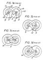
- FIG. 1a to 1d of the accompanying drawings shows a pair of rotors 5,8 mounted on respective shafts 1A, 1B for rotation about the shafts in the direction shown by the arrows with the claws 7,13 closely engaging the walls of a chamber 2.
- the claws scoop the liquid as they rotate, and the claw 7 of the rotor 8 which is associated with the inlet port 9 throws the liquid towards the outlet port 3 as it rotates from the positions 1a through 1b to 1c of Figure 1.
- the present invention is concerned with the provision a mechanical pump having at least one pair of intermeshing rotors in which any hydraulic hammering effect can be mitigated or prevented.
- a mechanical pump comprising first and second intermeshing rotors, each rotor being mounted for rotation on respective shafts and located in a pumping chamber, an inlet to the pumping chamber with which the first rotor is associated and an outlet from the pumping chamber with which the second rotor is associated, and a cavity formed in the surface of the second rotor immediately adjacent the outlet.
- the invention is primarily, but not exclusively, concerned with pumps having a "claw" type rotor profile.
- the nature of the cavity must be such that any condensed liquid which is present in particular in the volume of gas or vapour being "swept" by the rotors is urged into the cavity and ejected therefrom when the swept volume communicates with the chamber outlet.
- the pump is one in which the inlet to the pumping chamber is formed as a port in a first wall of the pumping chamber and the outlet from the pumping chamber is formed as a port in an opposite wall of the pumping chamber.
- the cavity is positioned in a side of the second rotor which engages the wall of the chamber containing the outlet.
- the position of the cavity is such that the condensed liquid is urged into the cavity by centrifugal force.
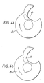
- the shape of the cavity is not important but preferably the shape is such that condensed liquid is retained within the cavity despite the rotation of the rotor and the centrifugal forces caused thereby. This can be achieved, for example, by arranging for the cavity to be substantially cup-shaped and extending in a direction such that centrifugally driven liquid is urged to the base of the cup before being deposited in the chamber outlet.
- the pump may comprise a plurality of individual chambers each having its own pair of rotors, some or, preferably, all of which may have cavities in accordance with the invention.
- the shafts on which the rotors are mounted it is generally preferable for the shafts on which the rotors are mounted to be orientated vertically. It is also preferable for the inlet to be positioned in a wall in the top of the chamber and for the outlet to be positioned in a wall at the bottom of the chamber.
- the pumping chamber 10 of a mechanical pump contains intermeshing claw type rotors 5, 8 each mounted on a shaft (not shown) in a manner known per se .
- the rotor 5 rotates in a clockwise sense as indicated by the arrows whilst rotor 8 rotates in an anti-clockwise sense.
- said liquid When used to pump a vapour which during the pumping operation condenses to a liquid, said liquid will be trapped in the space 12 between the rotors 5, 8at a time when the outlet port 3 is closed. As a consequence, the liquid can create a hammering effect between the rotors 5, 8 which can lead to mechanical failure.
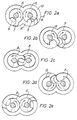
- the rotor 5 which is associated with the outlet port 3 is formed with a cavity 6 on its surface immediately adjacent the side wall 4 in which the outlet port 3 is formed.
- the shape and location of the cavity 6 and its relation to the outlet port 3 is illustrated in Figures 2a to 2e and Figure 3.
- a cavity 6 is provided in the rotor face associated with the outlet port at each stage. In all cases, the position of the cavity is such that it does not interfere with the basic operation of the pump.
Landscapes
- Engineering & Computer Science (AREA)
- Mechanical Engineering (AREA)
- General Engineering & Computer Science (AREA)
- Rotary Pumps (AREA)
- Applications Or Details Of Rotary Compressors (AREA)
- Structures Of Non-Positive Displacement Pumps (AREA)
Abstract
Description
- The present invention relates to mechanical pumps and in particular to mechanical vacuum pumps incorporating at least one pair of intermeshing rotors, especially rotors of the type known as "claw" rotors.
- When intermeshing claw type rotors are employed in mechanical vacuum pumps or compressors for use with gases or vapours which tend to condense or liquefy during the pumping or compression process, a hydraulic hammering effect is sometimes experienced. This hydraulic hammering effect is caused by the inability of the claw type rotors to expel liquid sufficiently rapidly from their swept volume. The liquid thus accumulates to give the hammering effect which can lead to mechanical failure.
- A typical claw type rotor mechanism is illustrated in Figures 1a to 1d of the accompanying drawings which shows a pair of
rotors claws 7,13 closely engaging the walls of achamber 2. - Any liquid formed in the volume swept by the
rotors pumping chamber 10, tends to move radially outwards under centrifugal force towards thestator walls 2 away from theoutlet port 3 which is located in theside wall 4 adjacent the centre of therotor 5. The claws scoop the liquid as they rotate, and the claw 7 of therotor 8 which is associated with the inlet port 9 throws the liquid towards theoutlet port 3 as it rotates from the positions 1a through 1b to 1c of Figure 1. - However, in the critical position between positions 1b and 1c, the
outlet port 3 is closed and this prevents expulsion of the liquid from thepumping chamber 10. The liquid is thereby trapped between therotors - The present invention is concerned with the provision a mechanical pump having at least one pair of intermeshing rotors in which any hydraulic hammering effect can be mitigated or prevented.
- In accordance with the present invention, there is provided a mechanical pump comprising first and second intermeshing rotors, each rotor being mounted for rotation on respective shafts and located in a pumping chamber, an inlet to the pumping chamber with which the first rotor is associated and an outlet from the pumping chamber with which the second rotor is associated, and a cavity formed in the surface of the second rotor immediately adjacent the outlet.
- The invention is primarily, but not exclusively, concerned with pumps having a "claw" type rotor profile. The nature of the cavity must be such that any condensed liquid which is present in particular in the volume of gas or vapour being "swept" by the rotors is urged into the cavity and ejected therefrom when the swept volume communicates with the chamber outlet.
- Ideally, the pump is one in which the inlet to the pumping chamber is formed as a port in a first wall of the pumping chamber and the outlet from the pumping chamber is formed as a port in an opposite wall of the pumping chamber.
- Preferably the cavity is positioned in a side of the second rotor which engages the wall of the chamber containing the outlet. Most preferably the position of the cavity is such that the condensed liquid is urged into the cavity by centrifugal force. In general the shape of the cavity is not important but preferably the shape is such that condensed liquid is retained within the cavity despite the rotation of the rotor and the centrifugal forces caused thereby. This can be achieved, for example, by arranging for the cavity to be substantially cup-shaped and extending in a direction such that centrifugally driven liquid is urged to the base of the cup before being deposited in the chamber outlet.
- For the avoidance of any doubt, the pump may comprise a plurality of individual chambers each having its own pair of rotors, some or, preferably, all of which may have cavities in accordance with the invention.
- In practice, it is generally preferable for the shafts on which the rotors are mounted to be orientated vertically. It is also preferable for the inlet to be positioned in a wall in the top of the chamber and for the outlet to be positioned in a wall at the bottom of the chamber.
- For a better understanding of the invention, reference will now be made, by way of example only, to the accompanying schematic drawings in which:-
- Figures 1a to 1d are transverse cross-sectional sketches through a pumping chamber of a known mechanical pump employing intermeshing claw type rotors and illustrating different relative positions of the rotors during a pumping operation;
- Figures 2a to 2e are transverse cross-sectional sketches through a pumping chamber of a mechanical pump employing intermesjing claw type rotors embodying the present invention and which illustrate different relative positions of the rotors during a pumping operation; and
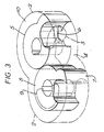
- Figure 3 is a perspective view of the rotors illustrated in Figure 2a.
- Figure 4 is a top view of two separate rotors for use in pumps of the invention showing differently shaped cavities therein.
- As shown in Figures 1a to 1d, the
pumping chamber 10 of a mechanical pump contains intermeshingclaw type rotors rotor 5 rotates in a clockwise sense as indicated by the arrows whilstrotor 8 rotates in an anti-clockwise sense. When used to pump a vapour which during the pumping operation condenses to a liquid, said liquid will be trapped in thespace 12 between therotors 5, 8at a time when theoutlet port 3 is closed. As a consequence, the liquid can create a hammering effect between therotors - Referring now to Figures 2a to 2e and Figure 3, the arrangement of the
pumping chamber 10 and therotors - The
rotor 5 which is associated with theoutlet port 3 is formed with a cavity 6 on its surface immediately adjacent theside wall 4 in which theoutlet port 3 is formed. The shape and location of the cavity 6 and its relation to theoutlet port 3 is illustrated in Figures 2a to 2e and Figure 3. - When the shafts on which the
rotors bottom sidewall 4 in which theoutlet port 3 is located. This liquid is thrown into the cavity 6 in position 2b to 2c, in particular by the action of claw 7 ofrotor 8, and under centrifugal force is discharged into theoutlet port 3 as it passes over it in the position 2e back to 2a. The cavity 6 expels a quantity of liquid, each revolution, sufficient to prevent build-up of liquid in the pumping chamber to such an extent that a hydraulic lock and resulting hammering could occur in position 2b to 2c betweenrotors - It will be appreciated that in a multi-stage claw type rotor pump which in its normal operative position has the axes of the rotors vertical, a cavity 6 is provided in the rotor face associated with the outlet port at each stage. In all cases, the position of the cavity is such that it does not interfere with the basic operation of the pump.
- Finally, with reference to Figure 4, there is shown two different shapes which can usefully be employed in pumps of the invention.
Claims (6)
Applications Claiming Priority (2)
| Application Number | Priority Date | Filing Date | Title |
|---|---|---|---|
| GB8825284 | 1988-10-28 | ||
| GB888825284A GB8825284D0 (en) | 1988-10-28 | 1988-10-28 | Improvements in mechanical pumps |
Publications (3)
| Publication Number | Publication Date |
|---|---|
| EP0366347A2 true EP0366347A2 (en) | 1990-05-02 |
| EP0366347A3 EP0366347A3 (en) | 1990-08-16 |
| EP0366347B1 EP0366347B1 (en) | 1993-07-07 |
Family
ID=10645948
Family Applications (1)
| Application Number | Title | Priority Date | Filing Date |
|---|---|---|---|
| EP89310702A Expired - Lifetime EP0366347B1 (en) | 1988-10-28 | 1989-10-18 | Improvements in mechanical pumps |
Country Status (6)
| Country | Link |
|---|---|
| US (1) | US5055017A (en) |
| EP (1) | EP0366347B1 (en) |
| JP (1) | JP3029202B2 (en) |
| DE (1) | DE68907465T2 (en) |
| ES (1) | ES2042004T3 (en) |
| GB (1) | GB8825284D0 (en) |
Cited By (4)
| Publication number | Priority date | Publication date | Assignee | Title |
|---|---|---|---|---|
| DE4233142A1 (en) * | 1992-10-02 | 1994-04-07 | Leybold Ag | Method for operating a claw vacuum pump and claw vacuum pump suitable for carrying out this operating method |
| DE19629174A1 (en) * | 1996-07-19 | 1998-01-22 | Leybold Vakuum Gmbh | Claw pump for producing vacuum |
| GB2426036A (en) * | 2005-05-10 | 2006-11-15 | Bernard Whicher | Vertical Northey compressor |
| CN108050061A (en) * | 2018-01-09 | 2018-05-18 | 中国石油大学(华东) | A kind of efficient claw rotor |
Families Citing this family (4)
| Publication number | Priority date | Publication date | Assignee | Title |
|---|---|---|---|---|
| RU2282063C1 (en) * | 2005-09-01 | 2006-08-20 | Виктор Павлович Шлапацкий | Rotary machine |
| US20070172790A1 (en) * | 2006-01-26 | 2007-07-26 | Midmark Corporation | Dental Vacuum System |
| CN104929942B (en) * | 2015-07-09 | 2016-10-05 | 中国石油大学(华东) | A Fully Engaged Claw Rotor Profile |
| CN113446065A (en) * | 2020-03-27 | 2021-09-28 | 信强(宁波)半导体设备制造有限公司 | Claw rotor and vacuum motor rotor combination |
Citations (2)
| Publication number | Priority date | Publication date | Assignee | Title |
|---|---|---|---|---|
| US3472445A (en) | 1968-04-08 | 1969-10-14 | Arthur E Brown | Rotary positive displacement machines |
| FR2109798A5 (en) | 1970-10-01 | 1972-05-26 | Atlas Copco Ab |
Family Cites Families (5)
| Publication number | Priority date | Publication date | Assignee | Title |
|---|---|---|---|---|
| US2058817A (en) * | 1931-12-22 | 1936-10-27 | Northey Rotary Engines Ltd | Rotary internal combustion engine |
| US2097037A (en) * | 1933-08-25 | 1937-10-26 | Northey Rotary Engines Ltd | Rotary compressor or vacuum pump |
| US2289371A (en) * | 1938-03-01 | 1942-07-14 | Jarvis C Marble | Rotary screw apparatus |
| GB1335045A (en) * | 1970-10-17 | 1973-10-24 | Brown A E | Rotary displacement machines |
| US4504201A (en) * | 1982-11-22 | 1985-03-12 | The Boc Group Plc | Mechanical pumps |
-
1988
- 1988-10-28 GB GB888825284A patent/GB8825284D0/en active Pending
-
1989
- 1989-10-18 EP EP89310702A patent/EP0366347B1/en not_active Expired - Lifetime
- 1989-10-18 DE DE89310702T patent/DE68907465T2/en not_active Expired - Fee Related
- 1989-10-18 ES ES198989310702T patent/ES2042004T3/en not_active Expired - Lifetime
- 1989-10-23 US US07/425,650 patent/US5055017A/en not_active Expired - Lifetime
- 1989-10-26 JP JP1279602A patent/JP3029202B2/en not_active Expired - Lifetime
Patent Citations (2)
| Publication number | Priority date | Publication date | Assignee | Title |
|---|---|---|---|---|
| US3472445A (en) | 1968-04-08 | 1969-10-14 | Arthur E Brown | Rotary positive displacement machines |
| FR2109798A5 (en) | 1970-10-01 | 1972-05-26 | Atlas Copco Ab |
Cited By (5)
| Publication number | Priority date | Publication date | Assignee | Title |
|---|---|---|---|---|
| DE4233142A1 (en) * | 1992-10-02 | 1994-04-07 | Leybold Ag | Method for operating a claw vacuum pump and claw vacuum pump suitable for carrying out this operating method |
| DE19629174A1 (en) * | 1996-07-19 | 1998-01-22 | Leybold Vakuum Gmbh | Claw pump for producing vacuum |
| GB2426036A (en) * | 2005-05-10 | 2006-11-15 | Bernard Whicher | Vertical Northey compressor |
| CN108050061A (en) * | 2018-01-09 | 2018-05-18 | 中国石油大学(华东) | A kind of efficient claw rotor |
| CN108050061B (en) * | 2018-01-09 | 2023-08-29 | 中国石油大学(华东) | High-efficiency claw type rotor |
Also Published As
| Publication number | Publication date |
|---|---|
| EP0366347B1 (en) | 1993-07-07 |
| DE68907465D1 (en) | 1993-08-12 |
| EP0366347A3 (en) | 1990-08-16 |
| JPH02185683A (en) | 1990-07-20 |
| JP3029202B2 (en) | 2000-04-04 |
| ES2042004T3 (en) | 1993-12-01 |
| GB8825284D0 (en) | 1988-11-30 |
| US5055017A (en) | 1991-10-08 |
| DE68907465T2 (en) | 1993-10-21 |
Similar Documents
| Publication | Publication Date | Title |
|---|---|---|
| EP0366347B1 (en) | Improvements in mechanical pumps | |
| EP0464970B1 (en) | Scroll type fluid machinery | |
| KR100573752B1 (en) | Volumetric machines for press media | |
| US8500425B2 (en) | Roots pumps | |
| EP0594461A1 (en) | Vacuum pumps | |
| US5697771A (en) | Vacuum pump with oil separator | |
| US6129534A (en) | Vacuum pumps | |
| EP1130264B1 (en) | Compound vacuum pumps | |
| EP0965758A2 (en) | Vacuum pump | |
| KR100497982B1 (en) | Composite dry vacuum pump having roots and screw rotor | |
| US5494412A (en) | Oil delivery prevention device for horizontal type rotary compressor | |
| US4295794A (en) | Selective mode multi-stage vacuum pump | |
| US5044906A (en) | Screw rotor for screw pump device having negative torque on the female rotor | |
| US5314320A (en) | Screw vacuum pump with a reduced starting load | |
| US20140286797A1 (en) | Liquid-Ring Vacuum Pump and Impeller for a Liquid-Ring Vacuum Pump | |
| US5846066A (en) | Vacuum pumps with claw-type rotor and roots-type rotor near the outlet | |
| EP0679810A2 (en) | Scroll apparatus | |
| EP0172674B1 (en) | Scroll type fluid compressor | |
| US4943215A (en) | Multistage vacuum pump with bore for fouling removal | |
| JP3721587B2 (en) | Hermetic electric compressor | |
| JPH0681793A (en) | Closed compressor | |
| KR102759237B1 (en) | Multi dry vacuum pump comprising for different shape rotor | |
| KR100624982B1 (en) | Combined dry vacuum pump with multi-stage Roots type screw and screw type rotor | |
| KR102759236B1 (en) | Casing having powder receiving part for Dry vacuum pump and Dry vacuum pump including the same | |
| EP1024290A1 (en) | Vacuum pump systems |
Legal Events
| Date | Code | Title | Description |
|---|---|---|---|
| PUAI | Public reference made under article 153(3) epc to a published international application that has entered the european phase |
Free format text: ORIGINAL CODE: 0009012 |
|
| AK | Designated contracting states |
Kind code of ref document: A2 Designated state(s): CH DE ES FR GB IT LI NL SE |
|
| PGFP | Annual fee paid to national office [announced via postgrant information from national office to epo] |
Ref country code: LU Payment date: 19900621 Year of fee payment: 4 |
|
| PUAL | Search report despatched |
Free format text: ORIGINAL CODE: 0009013 |
|
| AK | Designated contracting states |
Kind code of ref document: A3 Designated state(s): CH DE ES FR GB IT LI NL SE |
|
| 17P | Request for examination filed |
Effective date: 19901114 |
|
| 17Q | First examination report despatched |
Effective date: 19910829 |
|
| GRAA | (expected) grant |
Free format text: ORIGINAL CODE: 0009210 |
|
| ITF | It: translation for a ep patent filed | ||
| AK | Designated contracting states |
Kind code of ref document: B1 Designated state(s): CH DE ES FR GB IT LI NL SE |
|
| PG25 | Lapsed in a contracting state [announced via postgrant information from national office to epo] |
Ref country code: NL Effective date: 19930707 Ref country code: SE Effective date: 19930707 |
|
| ET | Fr: translation filed | ||
| REF | Corresponds to: |
Ref document number: 68907465 Country of ref document: DE Date of ref document: 19930812 |
|
| PGFP | Annual fee paid to national office [announced via postgrant information from national office to epo] |
Ref country code: SE Payment date: 19930921 Year of fee payment: 5 |
|
| PGFP | Annual fee paid to national office [announced via postgrant information from national office to epo] |
Ref country code: NL Payment date: 19931031 Year of fee payment: 5 |
|
| REG | Reference to a national code |
Ref country code: ES Ref legal event code: FG2A Ref document number: 2042004 Country of ref document: ES Kind code of ref document: T3 |
|
| NLV1 | Nl: lapsed or annulled due to failure to fulfill the requirements of art. 29p and 29m of the patents act | ||
| PLBE | No opposition filed within time limit |
Free format text: ORIGINAL CODE: 0009261 |
|
| STAA | Information on the status of an ep patent application or granted ep patent |
Free format text: STATUS: NO OPPOSITION FILED WITHIN TIME LIMIT |
|
| 26N | No opposition filed | ||
| PGFP | Annual fee paid to national office [announced via postgrant information from national office to epo] |
Ref country code: ES Payment date: 19941013 Year of fee payment: 6 |
|
| PG25 | Lapsed in a contracting state [announced via postgrant information from national office to epo] |
Ref country code: ES Free format text: LAPSE BECAUSE OF NON-PAYMENT OF DUE FEES Effective date: 19951019 |
|
| PGFP | Annual fee paid to national office [announced via postgrant information from national office to epo] |
Ref country code: CH Payment date: 19981019 Year of fee payment: 10 |
|
| REG | Reference to a national code |
Ref country code: ES Ref legal event code: FD2A Effective date: 19990503 |
|
| PG25 | Lapsed in a contracting state [announced via postgrant information from national office to epo] |
Ref country code: LI Free format text: LAPSE BECAUSE OF NON-PAYMENT OF DUE FEES Effective date: 19991031 Ref country code: CH Free format text: LAPSE BECAUSE OF NON-PAYMENT OF DUE FEES Effective date: 19991031 |
|
| REG | Reference to a national code |
Ref country code: CH Ref legal event code: PL |
|
| REG | Reference to a national code |
Ref country code: GB Ref legal event code: IF02 |
|
| PG25 | Lapsed in a contracting state [announced via postgrant information from national office to epo] |
Ref country code: IT Free format text: LAPSE BECAUSE OF NON-PAYMENT OF DUE FEES Effective date: 20051018 |
|
| REG | Reference to a national code |
Ref country code: GB Ref legal event code: 732E |
|
| PGFP | Annual fee paid to national office [announced via postgrant information from national office to epo] |
Ref country code: DE Payment date: 20071130 Year of fee payment: 19 |
|
| REG | Reference to a national code |
Ref country code: FR Ref legal event code: TP |
|
| PGFP | Annual fee paid to national office [announced via postgrant information from national office to epo] |
Ref country code: FR Payment date: 20071017 Year of fee payment: 19 Ref country code: GB Payment date: 20071029 Year of fee payment: 19 |
|
| GBPC | Gb: european patent ceased through non-payment of renewal fee |
Effective date: 20081018 |
|
| REG | Reference to a national code |
Ref country code: FR Ref legal event code: ST Effective date: 20090630 |
|
| PG25 | Lapsed in a contracting state [announced via postgrant information from national office to epo] |
Ref country code: DE Free format text: LAPSE BECAUSE OF NON-PAYMENT OF DUE FEES Effective date: 20090501 |
|
| PG25 | Lapsed in a contracting state [announced via postgrant information from national office to epo] |
Ref country code: FR Free format text: LAPSE BECAUSE OF NON-PAYMENT OF DUE FEES Effective date: 20081031 |
|
| PG25 | Lapsed in a contracting state [announced via postgrant information from national office to epo] |
Ref country code: GB Free format text: LAPSE BECAUSE OF NON-PAYMENT OF DUE FEES Effective date: 20081018 |