EP0366286B1 - A method and apparatus for processing electrical signals - Google Patents
A method and apparatus for processing electrical signals Download PDFInfo
- Publication number
- EP0366286B1 EP0366286B1 EP89310138A EP89310138A EP0366286B1 EP 0366286 B1 EP0366286 B1 EP 0366286B1 EP 89310138 A EP89310138 A EP 89310138A EP 89310138 A EP89310138 A EP 89310138A EP 0366286 B1 EP0366286 B1 EP 0366286B1
- Authority
- EP
- European Patent Office
- Prior art keywords
- electrical signal
- ratio
- level
- log
- minimum value
- Prior art date
- Legal status (The legal status is an assumption and is not a legal conclusion. Google has not performed a legal analysis and makes no representation as to the accuracy of the status listed.)
- Expired - Lifetime
Links
Images
Classifications
-
- G—PHYSICS
- G01—MEASURING; TESTING
- G01H—MEASUREMENT OF MECHANICAL VIBRATIONS OR ULTRASONIC, SONIC OR INFRASONIC WAVES
- G01H1/00—Measuring characteristics of vibrations in solids by using direct conduction to the detector
Definitions
- the present invention relates to a method and apparatus for processing electrical signals in order to recognise signal features indicative of variations in a process producing the electrical signals, and is particularly of interest for acoustic emissions or stress waves detected by transducers.
- Acoustic emission or stress wave activity is associated with operating machinery or processes, and is produced as a result of friction or impacts taking place during the operation of the machinery or process.
- a transducer detects the acoustic emissions and produces an electrical signal, which corresponds to the acoustic emission activity.
- the level of the electrical signal is measured, for example the mean level (RMS level) as disclosed at page 213 of the Nondestructive Testing Handbook, Second Edition, Volume 5, Acoustic Emission Testing, American Society for Nondestructive Testing under the heading "Root Mean Square Parameter”.
- RMS level mean level
- a good component operating under normal conditions gives a relatively low electrical signal level, corresponding to a relatively low acoustic emission activity whereas a bad component under normal conditions gives a relatively high electrical signal level, corresponding to a relatively high acoustic emission activity.
- a good component operating under adverse conditions also gives a relatively high electrical signal level.
- This method is therefore only suitable for use at a fixed operational condition, or some method of normalising the electrical signal level measurement with respect to the operating conditions is required.
- the acoustic emission activity from a rotating structure increases with rotational speed, it would be necessary to normalise for different rotational speeds.
- this type of measurement is sensitive to the detection sensitivity of the transducer during the measurement.
- the ratio of the peak level of the electrical signal to the mean level (RMS level) of the electrical signal is measured as shown in US3677072.
- the ratio of the peak level of the electrical signal to the mean of the electrical signal provides a measure of variations in the nature or form of the source processes producing the acoustic emissions enabling the occurrence of distress to be detected due to the increased occurrence of transient signal excursions.
- This method has the advantage of being self normalising since to a first approximation it is independent of the operating condition and variations in signal detection sensitivity.
- a disadvantage of this method is the susceptibility of the measurement to spurious electrical noise signals such as those caused by electromagnetic switching transients, which can give rise to relatively high ratios of peak level of electrical signal to mean level of electrical signal.
- a third method measures the amount of electrical signal which exceeds a predetermined threshold level as disclosed at pages 213-214 of the Nondestructive Testing Handbook, Second Edition, Volume 5, Acoustic Emission Testing, American Society for Nondestructive Testing under the heading "Signal Above Threshold".
- the threshold level floats dependent upon the electrical signal level viewed over a longer time period.
- the threshold level may be two times the mean level of the electrical signal.
- This method also has the advantage of being self normalising.
- a disadvantage of this method is that as the number of transient signal excursions per unit time increases there is also a tendency for the floating threshold level to rise.
- the present invention seeks to provide a method and apparatus for processing electrical signals in order to recognise signal features indicative of variations in the process producing them which overcomes the problems associated with the prior art methods and apparatus.
- the present invention provides a method of processing electrical signals in order to recognise signal features indicative of variations in the process producing the electrical signals, comprising measuring the minimum value of the electrical signal, measuring the mean value of the electrical signal, determining the ratio of the mean value of the electrical signal to the minimum value of the electrical signal, monitoring said ratio for variations of the ratio which are indicative of variations in the process producing the electrical signal.
- the electrical signals may correspond to the acoustic emission activity generated by a process.
- the electrical signal may correspond to the intensity of the acoustic activity.
- the electrical signal may correspond to the level of the acoustic activity.
- the electrical signal may correspond to a power of the level of the acoustic emission activity.
- the electrical signal may correspond to the square of the level of the acoustic emission activity.
- the present invention also provides an apparatus for processing acoustic emissions in order to recognise features indicative of variations in the process producing the acoustic emissions
- an apparatus for processing acoustic emissions comprising at least one transducer for being acoustically coupled to a source producing acoustic emissions and arranged to detect the acoustic emissions and to produce an electrical signal dependent upon the acoustic emission activity, means to measure the minimum value of the electrical signal, means to measure the mean value of the electrical signal and means to determine the ratio of the mean value of the electrical signal to the minimum value of the electrical signal, variations in said ratio being indicative of variations in the process producing the acoustic emissions.
- Divider means may measure the ratio of the mean value of the electrical signal to the minimum value of the electrical signal.
- a first logarithmic amplifier means may produce the log of the mean value of the electrical signal
- a second logarithmic amplifier means may produce the log of the minimum value of the electrical signal
- subtractor means subtracts the log of the minimum value of the electrical signal from the log of the mean value of the electrical signal to determine the ratio of the means value of the electrical signal to the minimum value of the electrical signal.
- Logarithmic amplifier means may produce the log of the electrical signal, the means to measure the minimum value of the electrical signal measures the minimum value of the log of the electrical signal, the means to measure the mean value of the electrical signal measures the mean value of the log of the electrical signal, subtractor means subtracts the minimum value of the log of the electrical signal from the mean value of the log of the electrical signal to determine the ratio of the mean value of the log of the electrical signal to the minimum value of the log of the electrical signal.
- the apparatus 10 comprises a transducer 12 which is acoustically coupled to a source process of acoustic emissions.
- the transducer 12 is coupled to a machine, an industrial process or other structure in which acoustic emissions, stress waves or vibrations are generated as a result of the operation of the machine, industrial process or other reasons in the structure.
- the acoustic emissions are commonly generated as a result of frictional processes and impacts.
- the transducer 12 is arranged to detect the acoustic emissions generated by or in the machine, industrial process or structure and to produce an electrical signal dependent upon the acoustic emission activity detected.
- the transducer 12 is commonly a piezoceramic element although other suitable types of transducer may be used, more than one transducer may be used.
- the electrical signal produced by the transducer 12 is supplied to an amplifier 14.
- the amplifier 14 amplifies the electrical signal and may incorporate filters to select the required frequency band or frequency bands.
- the amplified electrical signal is then supplied to a signal enveloper 16 which envelopes the electrical signal.
- the enveloped electrical signal is supplied to a mean level detector 18 and to a minimum level detector 20.
- the mean level detector 18 measures the mean, or average, level of the electrical signal corresponding to the mean level of the acoustic emission activity by integrating the electrical signal level over the measuring time period.
- the minimum level detector 20 measures the minimum level of the electrical signal corresponding to the minimum level of the acoustic emission activity.
- the mean level of the electrical signal as detected by the mean level detector 18, and the minimum level of the electrical signal as detected by the minimum level detector 20 are supplied to a ratio measurer 22.
- the ratio measurer 22 determines the ratio of the mean level of the electrical signal to the minimum level of the electrical signal, which corresponds to the ratio of the mean level of the acoustic emission activity to the minimum level of the acoustic emission activity.
- the ratio measurer 22 divides the mean level of the electrical signal by the minimum level of the electrical signal and supplies the output to an output terminal 24.
- the output terminal 24 may be connected to a display to show the ratio, or may be connected to an alarm such that when the ratio reaches a predetermined value the alarm is operated, or may be connected to a control device such that a feedback signal controls the operation of the machine or process e.g. to reduce the speed of the rotating structure or to add lubricant.
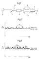
- Figures 2 and 3 show graphs of acoustic emission or stress wave activity level versus time for low amounts of distress and high amounts of distress respectively.
- the mean level of the acoustic emission activity and the minimum level of the acoustic emission activity are shown in both cases. In figure 2 there are relatively few transient excursions 26 per unit time whereas in figure 3 there are a relatively high number of transient excursions per unit time.
- the minimum level of the acoustic emission activity and corresponding electrical signal level remains the same in both figures, but the mean level of the acoustic emission activity and corresponding electrical signal level increases with the number of transient excursions per unit time.
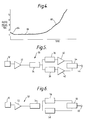
- the envelope of the electrical signal and corresponding acoustic emission activity is characterised in terms of the ratio of the mean level of the electrical signal to the minimum level of the electrical signal to give a graph as shown in figure 4.
- a smooth envelope electrical signal ie an electrical signal with relatively few and relatively small transient excursions, gives a ratio close to one whereas a rough envelope electrical signal, ie an electrical signal with a relatively high number and relatively large transient excursions, gives a ratio much greater than one, dependent upon the number of excursions and the level of the excursions.
- the area 64 of the graph corresponds to initial bedding in of the rotational structure, area 66 corresponds to normal operation and area 68 corresponds to increasing distress.
- This method has the advantages of the second and third prior art methods of being self compensating for variations in the overall level of the electrical signal such as those caused by variation in the operating conditions of the machine or industrial process, ie speed, or changes in transducer sensitivity.
- This method has the advantage of not being significantly affected by electromagnetic switching transients since these do not affect the minimum level of the electrical signal, and only marginally affect the mean level of the electrical signal as it is an integration of the electrical signal level over the measurement period.
- This method also has the advantage of being able to cope with very high numbers of transient excursions per unit time whilst still giving the desired characterisation.
- This method is also extremely simple to implement compared to the prior art methods.
- a further apparatus 30 for processing acoustic emissions is shown in Figure 5, which also comprises a transducer 12 acoustically coupled to a source process and arranged to detect the acoustic emissions generated by the source process and to produce an electrical signal dependent upon the acoustic emission activity detected.
- the electrical signal is supplied to an amplifier 32 which amplifies the signal.
- the amplifier 32 may also contain filters as in Figure 1.
- the amplified electrical signal is supplied to a signal enveloper 34 which envelopes the electrical signal.
- the enveloped electrical signal is supplied to a mean level detector 36 and to a minimum level detector 38.
- the mean level detector 36 measures the mean, or average, level of the electrical signal corresponding to the mean level of the acoustic emission activity by integrating the electrical signal over the measuring time period.
- the minimum level detector 38 measures the minimum level of the electrical signal corresponding to the minimum level of the acoustic emission activity.
- the mean level of the electrical signal as detected by the mean level detector 36 and the minimum level of the electrical signal as detected by the minimum level detector 38 are supplied to logarithmic amplifiers 40 and 42 respectively.
- the logarithmic amplifier 40 produces an output signal which is the log of the mean level of the electrical signal
- the logarithmic amplifier 42 produces an output signal which is the log of the minimum level of the electrical signal.
- the output signals of the logarithmic amplifiers 40 and 42 are supplied to a ratio measurer 44 which measures the ratio of the mean level of the electrical signal to the minimum level of the electrical signal by subtracting the log of the minimum level of the electrical signal from the log of the mean level of the electrical signal and supplying the result to an output 46.
- FIG. 6 Another apparatus 50 for processing acoustic emissions is shown in figure 6, this also comprises a transducer 12 acoustically coupled to a source process and arranged to detect the acoustic emissions generated by the source process and to produce an electrical signal dependent upon the acoustic emission activity detected.
- the electrical signal is supplied to a logarithmic amplifier 52 which amplifies the signal and produces a log of the electrical signal.
- the logarithmic amplifier 52 may also contain filters for the same purpose as those in figure 1.
- the logarithmic electrical signal is supplied to a signal enveloper 54.
- the enveloped logarithmic electrical signal is supplied to a mean level detector 56 and to a minimum level detector 58 to measure the mean level of the enveloped logarithmic electrical signal and the minimum level of the enveloped logarithmic electrical signal.
- the mean level of the logarithmic electrical signal and the minimum level of the logarithmic electrical signal are supplied to a ratio measurer 60 which measures the ratio of the mean electrical signal level to the minimum electrical signal level.
- the ratio measurer 60 comprises a subtracter amplifier which subtracts the minimum level of the logarithmic electrical signal from the mean level of the logarithmic electrical signal to give the log of the ratio and supplies the result to an output 62.
- the invention is intended to cover the concept of measuring the ratio of the mean electrical signal to the minimum electrical signal whether the electrical signal corresponds to an acoustic emission level, acoustic emission intensity, the acoustic emission level squared or some other power of the acoustic emission level or acoustic emission intensity ie (Mean Acoustic Emission level)2 (Minimum Acoustic Emission level)2.
- the characterisation of the electrical signal may be carried out either linearly or logarithmically.
- the description has referred to a method of processing electrical signals, corresponding to acoustic emission activity, in order to recognise features indicative of variations in the process producing the acoustic emissions.
- the method of processing electrical signals is equally applicable to electrical signals corresponding to other phenomena or parameters.
- the mean value means any mean or average value between extreme values, for example the arithmetical mean.
Priority Applications (1)
| Application Number | Priority Date | Filing Date | Title |
|---|---|---|---|
| AT89310138T ATE99414T1 (de) | 1988-10-22 | 1989-10-04 | Verfahren und anordnung zur verarbeitung elektrischer signale. |
Applications Claiming Priority (2)
| Application Number | Priority Date | Filing Date | Title |
|---|---|---|---|
| GB888824793A GB8824793D0 (en) | 1988-10-22 | 1988-10-22 | Method & apparatus for processing electrical signals |
| GB8824793 | 1988-10-22 |
Publications (3)
| Publication Number | Publication Date |
|---|---|
| EP0366286A2 EP0366286A2 (en) | 1990-05-02 |
| EP0366286A3 EP0366286A3 (en) | 1991-11-13 |
| EP0366286B1 true EP0366286B1 (en) | 1993-12-29 |
Family
ID=10645643
Family Applications (1)
| Application Number | Title | Priority Date | Filing Date |
|---|---|---|---|
| EP89310138A Expired - Lifetime EP0366286B1 (en) | 1988-10-22 | 1989-10-04 | A method and apparatus for processing electrical signals |
Country Status (6)
| Country | Link |
|---|---|
| US (1) | US5005415A (ja) |
| EP (1) | EP0366286B1 (ja) |
| JP (1) | JPH02236424A (ja) |
| AT (1) | ATE99414T1 (ja) |
| DE (1) | DE68911848T2 (ja) |
| GB (1) | GB8824793D0 (ja) |
Families Citing this family (16)
| Publication number | Priority date | Publication date | Assignee | Title |
|---|---|---|---|---|
| US5176032A (en) * | 1990-02-21 | 1993-01-05 | Stresswave Technology Limited | Method and apparatus for processing electrical signals and a stress wave sensor |
| GB9003878D0 (en) * | 1990-02-21 | 1990-04-18 | Stresswave Tech | A method and apparatus for processing electrical signals |
| US5328460A (en) * | 1991-06-21 | 1994-07-12 | Pacesetter Infusion, Ltd. | Implantable medication infusion pump including self-contained acoustic fault detection apparatus |
| US5637799A (en) * | 1992-04-15 | 1997-06-10 | The United States Of America As Represented By The Administrator Of The National Aeronautics And Space Administration | Method and apparatus for evaluating multilayer objects for imperfections |
| US5625150A (en) * | 1994-08-18 | 1997-04-29 | General Electric Company | Integrated acoustic leak detection sensor subsystem |
| US5633468A (en) * | 1995-09-13 | 1997-05-27 | The Babcock & Wilcox Company | Monitoring of fuel particle coating cracking |
| US5827974A (en) * | 1996-02-03 | 1998-10-27 | Nussinovitch; Amos | System for measuring the crispiness of materials |
| DE19647792A1 (de) * | 1996-11-19 | 1998-05-28 | Bosch Gmbh Robert | Vorrichtung und Verfahren zur Körperschall-Güteprüfung |
| US5852793A (en) * | 1997-02-18 | 1998-12-22 | Dme Corporation | Method and apparatus for predictive diagnosis of moving machine parts |
| US6101881A (en) * | 1997-09-16 | 2000-08-15 | Ut Automotive Dearborn, Inc. | Non-contact locked terminal tester |
| US6155118A (en) * | 1998-05-26 | 2000-12-05 | Trw Inc. | Apparatus for testing a device that generates an audible sound in a vehicle occupant compartment |
| EP1054243B1 (fr) * | 1999-05-19 | 2006-01-04 | Vibro-Meter Sa | Procédé et système de mesure vibratoire combinée |
| DE102005020901A1 (de) * | 2005-05-04 | 2006-11-16 | Siemens Ag | Verfahren und System zur Diagnose von mechanischen, elektromechanischen oder fluidischen Komponenten |
| US10161919B2 (en) | 2016-10-25 | 2018-12-25 | Fisher Controls International Llc | Acoustic emission sensors with integral acoustic generators |
| US10161912B2 (en) * | 2016-01-11 | 2018-12-25 | Fisher Controls International Llc | Methods and apparatus to test acoustic emission sensors |
| US10345273B2 (en) | 2016-01-11 | 2019-07-09 | Fisher Controls International Llc | Methods and apparatus to verify operation of acoustic emission sensors |
Citations (1)
| Publication number | Priority date | Publication date | Assignee | Title |
|---|---|---|---|---|
| US3677072A (en) * | 1970-10-30 | 1972-07-18 | Gen Electric | Damage detection method and apparatus for machine elements utilizing vibrations therefrom |
Family Cites Families (8)
| Publication number | Priority date | Publication date | Assignee | Title |
|---|---|---|---|---|
| US3913084A (en) * | 1973-03-26 | 1975-10-14 | Wisconsin Alumni Res Found | Noise quality detector for electric motors or other machines |
| DE2713640A1 (de) * | 1977-03-28 | 1978-10-12 | Kraftwerk Union Ag | Verfahren zur ueberwachung einer anlage und anordnung zur durchfuehrung des verfahrens |
| US4111035A (en) * | 1977-11-07 | 1978-09-05 | General Motors Corporation | Engine knock signal generating apparatus with noise channel inhibiting feedback |
| CA1105604A (en) * | 1978-06-07 | 1981-07-21 | James H. Rogers | Method and system for detecting plate clashing in disc refiners |
| US4304629A (en) * | 1979-05-07 | 1981-12-08 | Westinghouse Electric Corp. | Object impact discriminator |
| JPS6064250A (ja) * | 1983-09-20 | 1985-04-12 | Niigata Eng Co Ltd | 工具損傷検出装置 |
| US4609994A (en) * | 1984-01-16 | 1986-09-02 | The University Of Manitoba | Apparatus for continuous long-term monitoring of acoustic emission |
| JPS60201206A (ja) * | 1984-03-26 | 1985-10-11 | Omron Tateisi Electronics Co | 工具摩耗度検出装置 |
-
1988
- 1988-10-22 GB GB888824793A patent/GB8824793D0/en active Pending
-
1989
- 1989-10-04 AT AT89310138T patent/ATE99414T1/de not_active IP Right Cessation
- 1989-10-04 EP EP89310138A patent/EP0366286B1/en not_active Expired - Lifetime
- 1989-10-04 DE DE89310138T patent/DE68911848T2/de not_active Expired - Lifetime
- 1989-10-06 US US07/417,920 patent/US5005415A/en not_active Expired - Lifetime
- 1989-10-23 JP JP1275762A patent/JPH02236424A/ja active Pending
Patent Citations (1)
| Publication number | Priority date | Publication date | Assignee | Title |
|---|---|---|---|---|
| US3677072A (en) * | 1970-10-30 | 1972-07-18 | Gen Electric | Damage detection method and apparatus for machine elements utilizing vibrations therefrom |
Non-Patent Citations (1)
| Title |
|---|
| Nondestructive Testing Handbook, 2nd edition, vol. 5, pages 213-214; R.K. Miller et al * |
Also Published As
| Publication number | Publication date |
|---|---|
| DE68911848D1 (de) | 1994-02-10 |
| EP0366286A3 (en) | 1991-11-13 |
| EP0366286A2 (en) | 1990-05-02 |
| DE68911848T2 (de) | 1994-04-14 |
| ATE99414T1 (de) | 1994-01-15 |
| US5005415A (en) | 1991-04-09 |
| GB8824793D0 (en) | 1988-11-30 |
| JPH02236424A (ja) | 1990-09-19 |
Similar Documents
| Publication | Publication Date | Title |
|---|---|---|
| EP0366286B1 (en) | A method and apparatus for processing electrical signals | |
| EP0227138B1 (en) | Means for detecting faults or defects in moving machine parts | |
| US4478082A (en) | Method and apparatus for detecting rubbing in a rotary machine | |
| US4991442A (en) | Method and apparatus for detecting cracks in bearings | |
| US4530240A (en) | Method and apparatus for diagnosing machine condition | |
| CA2098943A1 (en) | System and method for dectecting cutting tool failure | |
| US5176032A (en) | Method and apparatus for processing electrical signals and a stress wave sensor | |
| US4455862A (en) | Method and apparatus of detecting engine knocking | |
| US4089055A (en) | Electronic monitoring apparatus | |
| US5101162A (en) | Method and apparatus for testing the response of a stress wave sensor | |
| US5473315A (en) | Enhanced means of processing signals used to interpret the condition of machinery | |
| US4444042A (en) | Engine-knock detection method and apparatus | |
| US3930405A (en) | Method and means for measuring acoustic emissions | |
| US3968697A (en) | Sound level meter | |
| GB2049935A (en) | Apparatus for monitoring vibrations in rotating machinery | |
| EP0443714B1 (en) | A method and apparatus for processing electrical signals and a stress wave sensor | |
| JPS57172218A (en) | Detector for tool defect | |
| US5074150A (en) | Instrument for the measurement of the cavitation or ebullition rate in a liquid | |
| JP2003114250A (ja) | 回転電機の部分放電検出装置 | |
| JPS57190212A (en) | Device for detecting abnormality of measuring device | |
| JPS6120837A (ja) | ラビング検出方法 | |
| RU2006806C1 (ru) | Способ контроля герметичности изделий | |
| SU1111049A1 (ru) | Устройство дл контрол подшипников качени | |
| RU2158901C2 (ru) | Ультразвуковой толщиномер | |
| JPS6343708B2 (ja) |
Legal Events
| Date | Code | Title | Description |
|---|---|---|---|
| PUAI | Public reference made under article 153(3) epc to a published international application that has entered the european phase |
Free format text: ORIGINAL CODE: 0009012 |
|
| AK | Designated contracting states |
Kind code of ref document: A2 Designated state(s): AT BE CH DE ES FR GB IT LI LU NL SE |
|
| PUAL | Search report despatched |
Free format text: ORIGINAL CODE: 0009013 |
|
| AK | Designated contracting states |
Kind code of ref document: A3 Designated state(s): AT BE CH DE ES FR GB IT LI LU NL SE |
|
| 17P | Request for examination filed |
Effective date: 19911112 |
|
| 17Q | First examination report despatched |
Effective date: 19930114 |
|
| RAP1 | Party data changed (applicant data changed or rights of an application transferred) |
Owner name: ROLLS-ROYCE DSV LIMITED |
|
| GRAA | (expected) grant |
Free format text: ORIGINAL CODE: 0009210 |
|
| ITF | It: translation for a ep patent filed |
Owner name: BARZANO' E ZANARDO MILA |
|
| AK | Designated contracting states |
Kind code of ref document: B1 Designated state(s): AT BE CH DE ES FR GB IT LI LU NL SE |
|
| PG25 | Lapsed in a contracting state [announced via postgrant information from national office to epo] |
Ref country code: SE Effective date: 19931229 Ref country code: NL Effective date: 19931229 Ref country code: LI Effective date: 19931229 Ref country code: ES Free format text: THE PATENT HAS BEEN ANNULLED BY A DECISION OF A NATIONAL AUTHORITY Effective date: 19931229 Ref country code: CH Effective date: 19931229 Ref country code: BE Effective date: 19931229 Ref country code: AT Effective date: 19931229 |
|
| REF | Corresponds to: |
Ref document number: 99414 Country of ref document: AT Date of ref document: 19940115 Kind code of ref document: T |
|
| REF | Corresponds to: |
Ref document number: 68911848 Country of ref document: DE Date of ref document: 19940210 |
|
| ET | Fr: translation filed | ||
| REG | Reference to a national code |
Ref country code: CH Ref legal event code: PL |
|
| NLV1 | Nl: lapsed or annulled due to failure to fulfill the requirements of art. 29p and 29m of the patents act | ||
| PG25 | Lapsed in a contracting state [announced via postgrant information from national office to epo] |
Ref country code: LU Free format text: LAPSE BECAUSE OF NON-PAYMENT OF DUE FEES Effective date: 19941031 |
|
| PLBE | No opposition filed within time limit |
Free format text: ORIGINAL CODE: 0009261 |
|
| STAA | Information on the status of an ep patent application or granted ep patent |
Free format text: STATUS: NO OPPOSITION FILED WITHIN TIME LIMIT |
|
| 26N | No opposition filed | ||
| REG | Reference to a national code |
Ref country code: GB Ref legal event code: IF02 |
|
| PGFP | Annual fee paid to national office [announced via postgrant information from national office to epo] |
Ref country code: FR Payment date: 20040913 Year of fee payment: 16 |
|
| PGFP | Annual fee paid to national office [announced via postgrant information from national office to epo] |
Ref country code: GB Payment date: 20040916 Year of fee payment: 16 |
|
| PGFP | Annual fee paid to national office [announced via postgrant information from national office to epo] |
Ref country code: DE Payment date: 20040917 Year of fee payment: 16 |
|
| PG25 | Lapsed in a contracting state [announced via postgrant information from national office to epo] |
Ref country code: IT Free format text: LAPSE BECAUSE OF NON-PAYMENT OF DUE FEES;WARNING: LAPSES OF ITALIAN PATENTS WITH EFFECTIVE DATE BEFORE 2007 MAY HAVE OCCURRED AT ANY TIME BEFORE 2007. THE CORRECT EFFECTIVE DATE MAY BE DIFFERENT FROM THE ONE RECORDED. Effective date: 20051004 Ref country code: GB Free format text: LAPSE BECAUSE OF NON-PAYMENT OF DUE FEES Effective date: 20051004 |
|
| PG25 | Lapsed in a contracting state [announced via postgrant information from national office to epo] |
Ref country code: DE Free format text: LAPSE BECAUSE OF NON-PAYMENT OF DUE FEES Effective date: 20060503 |
|
| GBPC | Gb: european patent ceased through non-payment of renewal fee |
Effective date: 20051004 |
|
| PG25 | Lapsed in a contracting state [announced via postgrant information from national office to epo] |
Ref country code: FR Free format text: LAPSE BECAUSE OF NON-PAYMENT OF DUE FEES Effective date: 20060630 |
|
| REG | Reference to a national code |
Ref country code: FR Ref legal event code: ST Effective date: 20060630 |