EP0366199A1 - Dispositif de prise de vues muni d'un capteur de transfert de trame convenant pour un transfert d'information selon le principe dit d'accordéon - Google Patents
Dispositif de prise de vues muni d'un capteur de transfert de trame convenant pour un transfert d'information selon le principe dit d'accordéon Download PDFInfo
- Publication number
- EP0366199A1 EP0366199A1 EP89202673A EP89202673A EP0366199A1 EP 0366199 A1 EP0366199 A1 EP 0366199A1 EP 89202673 A EP89202673 A EP 89202673A EP 89202673 A EP89202673 A EP 89202673A EP 0366199 A1 EP0366199 A1 EP 0366199A1
- Authority
- EP
- European Patent Office
- Prior art keywords
- radiation
- information
- sensor
- transfer
- image
- Prior art date
- Legal status (The legal status is an assumption and is not a legal conclusion. Google has not performed a legal analysis and makes no representation as to the accuracy of the status listed.)
- Withdrawn
Links
- 230000005855 radiation Effects 0.000 claims abstract description 30
- 102100032757 Cysteine-rich protein 2 Human genes 0.000 description 6
- 101000942088 Homo sapiens Cysteine-rich protein 2 Proteins 0.000 description 6
- 101000851593 Homo sapiens Separin Proteins 0.000 description 6
- 101100425560 Rattus norvegicus Tle4 gene Proteins 0.000 description 4
- 101100327317 Saccharomyces cerevisiae (strain ATCC 204508 / S288c) CDC1 gene Proteins 0.000 description 4
- 230000010354 integration Effects 0.000 description 4
- 230000004888 barrier function Effects 0.000 description 3
- 239000004973 liquid crystal related substance Substances 0.000 description 2
- 101000765037 Mus musculus Class E basic helix-loop-helix protein 40 Proteins 0.000 description 1
- 230000000694 effects Effects 0.000 description 1
Images

Classifications
-
- H—ELECTRICITY
- H04—ELECTRIC COMMUNICATION TECHNIQUE
- H04N—PICTORIAL COMMUNICATION, e.g. TELEVISION
- H04N25/00—Circuitry of solid-state image sensors [SSIS]; Control thereof
- H04N25/50—Control of the SSIS exposure
- H04N25/53—Control of the integration time
-
- H—ELECTRICITY
- H01—ELECTRIC ELEMENTS
- H01L—SEMICONDUCTOR DEVICES NOT COVERED BY CLASS H10
- H01L27/00—Devices consisting of a plurality of semiconductor or other solid-state components formed in or on a common substrate
- H01L27/14—Devices consisting of a plurality of semiconductor or other solid-state components formed in or on a common substrate including semiconductor components sensitive to infrared radiation, light, electromagnetic radiation of shorter wavelength or corpuscular radiation and specially adapted either for the conversion of the energy of such radiation into electrical energy or for the control of electrical energy by such radiation
- H01L27/144—Devices controlled by radiation
- H01L27/146—Imager structures
- H01L27/148—Charge coupled imagers
-
- H—ELECTRICITY
- H04—ELECTRIC COMMUNICATION TECHNIQUE
- H04N—PICTORIAL COMMUNICATION, e.g. TELEVISION
- H04N25/00—Circuitry of solid-state image sensors [SSIS]; Control thereof
- H04N25/70—SSIS architectures; Circuits associated therewith
- H04N25/71—Charge-coupled device [CCD] sensors; Charge-transfer registers specially adapted for CCD sensors
- H04N25/72—Charge-coupled device [CCD] sensors; Charge-transfer registers specially adapted for CCD sensors using frame transfer [FT]
Definitions
- the invention relates to an image pick-up device comprising a frame transfer sensor suitable for information transfer in accordance with the accordion principle, which sensor comprises an image section comprising sensor image elements for converting incident radiation into charge packet information as picture information, a storage section coupled thereto and shielded from radiation for the purpose of picture information storage comprising sensor storage elements and a parallel-in, series-out shift register section coupled thereto and shielded from radiation comprising at least one row of sensor shift register elements and having at least one output for supplying a picture signal, the device for performing the accordion control including a time signal generator for applying at least clock pulse signals to control electrodes of the sensor, the information transfer in accordance with the accordion principle involving an information shift in the sensor with an openening, a transporting and a closing phase, the opening phase involving an enlargement of picture information elements and a transport of picture information, the transporting phase involving a transport of picture information and the closing phase involving a transport of picture information and a reduction of picture information elements at the appointed locations, said image
- An image pick-up device comprising a frame transfer sensor suitable for information transfer in accordance with the accordion principle is known from the Article "The accordion imager, a new solid-state image sensor" in the Journal Philips Technical Review, No. 1/2, December 1986, pp. 1 to 8. This Article describes that the transfer should be very fast to ensure that the charge packets which are on their way are not significantly influenced by incident light such as radiation.
- the shutter device generally has a rotary disc which is secured to a shaft driven by a motor. To interrupt the incidence of light, the rotary disc is rotated in front of the image section. If the image section is completely shielded by the rotary disc after a period of rotating the disc, the frame transfer is subsequently effected during the transfer period. This transfer may be or may not be effected in accordance with the accordion principle.
- an image pick-up device is characterized in that in the case of a partially local interruption of the incidence of radiation on the image section the information transfer in accordance with the accordion principle locally starts at said interruption and follows it with the continuing local interruption of the incidence of radiation.
- the image disturbance is reduced by using the extension of the accordion transfer which follows the continuing interruption of radiation.
- this image disturbance is caused by the fact that the image information in the image section during the known frame transfer period of five to seven line periods is removed therefrom in one abrupt action and that the display is effected pixel and line-sequentially in a field period.
- the human eye interprets the display of two offset images of the vertical contour as an oblique contour canting in the direction of movement. In the frame transfer according to the invention the abrupt action does not occur, but an even transfer takes place.
- the reference FT denotes a frame transfer sensor.
- An image section IP, a storage section SP and a shift register section SR are denoted at the sensor FT.
- the sections IP and SP comprise in known manner a two-dimensional pattern of sensor elements each (not shown). Numbers and formats of the sensor elements in the patterns may be equal or different.
- the section IP comprises sensor image elements for converting incident radiation such as, for example light into charge packet information as picture information.
- the storage section SP shielded from radiation for picture information storage comprises sensor storage elements.
- the parallel in, series out shift register section SR which is also shielded from radiation comprises at least one row of sensor shift register elements, which row is connected to at least one output OT for supplying a picture signal. The shieldings are indicated by means of shaded areas.
- Sensor control electrodes at the sections IP and SP are illustrated with reference to single electrodes EIP and ESP, respectively.
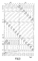
- the electrodes EIP and ESP are further shown in Fig. 3 which gives a pattern of logic 0s and 1s occurring at fourteen electrodes each.
- the pattern given is associated with an information transfer in accordance with the accordion principle, and the direction of this transfer is denoted by an arrow FTD in Figs. 1 and 3.
- the pattern of Fig. 3 is obtained by means of clock pulse signals CIP and CSP which are supplied by a time signal generator CC.
- the generator CC also applies a clock pulse signal CSR to the register section SR.
- the leads conveying the signals CIP, CSP and CSR are shown as a single leads but are formed as multiple leads in known manner for the transport of the various clock pulse signals at different frequencies or phases.
- the frame transfer sensor FT shown may be combined with a so-called interline sensor IL to a FIT sensor.
- Fig. 1 also shows a shutter device (SH, SHM) which consists of, for example a shutter pair SH shown with two shutters SH1 and SH2 and with a motor SHM which is coupled to the shutter pair SH via a drive shaft with a drive direction indicated by an arrow SHA. Since the shutter device (SH, SHM) is to be driven synchronously with the electrode control at the sensor FT, the generator CC applies a synchronizing signal CSH to the motor SHM.
- the shutter device (SH, SHM) is shown by way of example in Fig. 1.
- the motor SHM ensures that the shutters SH1 and SH2 move in front of the sensor FT at a speed indicated by an arrow v so that the incidence of radiation or light on the image section IP is interrupted during a period for the information transfer from image section IP to storage section SP.
- the interruption of the incidence of light is illustrated by means of a shaded area.
- an electronic shutter in front of the image section IP is feasible, which is formed, for example with a liquid crystal.
- the liquid crystal should be controlled in such a way that a shutter action occurs which is illustrated for Fig. 1 in Figs. 2a, 2b, 2c and 2d.
- Figs. 2a, 2b, 2c and 2d are associated with four positions, occurring in time, of the image section IP and the shutter SH2, subsequent to the position of the sensor FT and the shutters SH1 and SH2 shown in Fig. 1.
- Fig. 2a shows at an instant t10 that a small part of the image section IP is shielded.
- Fig. 2b shows that at an instant t20 the entire section is shielded.
- Fig. 2c is associated with an instant t30 occurring just after exposing the image section IP to light. The further exposure is shown in Fig. 2d at an instant t40.
- the instants t10, t20, t30 and t40 are shown as examples in Fig. 3 at the logic pattern.
- the reference t0 denotes an instant used as a periodical instant for the description of the operation of the image pick-up device according to Fig. 1.
- a logic pattern 01010101 etc. is present as an example at the control electrodes EIP1 to 14 of the image section IP. It is assumed in known manner that the logic 0 corresponds to a barrier induced in the sensor FT and the logic 1 corresponds to a potential well which may comprise a charge packet occurring in the sensor FT as picture information which is locally built up during a picture integration period. Furthermore it is assumed that at the instant t0 a logic pattern 00110011 etc.
- the instant t0 is considered to be the final instant of the picture integration period at the location of the electrode EIP14, while the storage section ESP no longer contains picture information. It is assumed that the shift register section SR, which is not shown, adjoins the storage section SP with the electrode ESP14. The number of fourteen electrodes has been taken for the sake of simplicity of the description, but in practice there are several hundreds of electrodes.
- the instant t0 is succeeded by an instant t1 at which the logic pattern at the electrodes EIP is unchanged, while the logic pattern 0011 changes over to 1001 at the electrodes ESP.
- the result is that the picture information charge packet which is present under the electrode EIP14 extends as far as under the electrode ESP1.
- the charge packet is present under the electrodes ESP1 and 2, while a widened barrier is present under the electrodes EIP14 and 13.
- the charge packet under the electrode EIP12 has extended as far as under the electrode EIP13.
- Fig. 3 illustrates the charge packet extensions with a square changing into a rectangle. Subsequently only an information transfer takes place.
- the closing phase of the accordion transfer starts at the electrode ESP14.
- a reduction of picture information elements at the appointed locations succeeds the transport of picture information in the transporting phase, as is illustrated by the rectangle and the square.
- the closing phase ends at the storage section SP, at the electrode ESP2.
- the closing phase starts at the image section IP.
- the image section IP is ready for the next picture information integration period at the location of the electrode EIP14. It is assumed that the logic pattern shown in Fig. 3 is associated with the instant t30 of Fig. 2c.
- the picture information from underneath the electrode EIP12 and stored under the electrode ESP12 is present under the electrodes ESP13 and 12.
- the picture information under the electrode ESP14 is passed on in a manner not shown to the adjacent shift register section SR. It will be evident from the further description of Fig. 3 that this picture information is incorrect.
- the storage section SP it holds that no clock pulses are applied thereto after the instant t40 during a subsequent line scan period associated with a picture signal.
- the parallel-in, series-out shift register section SR of Fig. 1 is controlled for the serial reading.
- the shift register section SR is parallel filled from the storage section SP in a manner not shown.
- a periodical logic pattern 0011 occurs during transport at the electrode ESP1, as holds true for all electrodes.
- the instant t42 shows that the pattern 11 periodically occurs at the electrodes ESP2 and 1 and EIP14. Consequently picture information is periodically withdrawn under the electrode EIP14 so that the information ultimately being present under the electrode ESP14 after a subsequent frame transfer is incorrect picture information, as has been described in the foregoing.
- a measure against this may be the constant supply of a logic 0 to the electrode ESP1 during the period between the instants t41 and t43, at least during the last part thereof with the transport of information under the electrode ESP2.
- an extra electrode could be arranged at the bounding line between the storage section SP and the image section IP for forming the barrier.
- Fig. 1 and Figs. 2a, 2b, 2c and 2d show that the shutter device (SH, SHM) interrupts the light radiation parallel to the bounding line between the storage section SP and the image section IP.
- SH shutter device
- the (extension) rate of the accordion transfer need not be equal to the rate v of the shutters SH1 and SH2.
- the extension rate of the opening phase of the accordion transfer during the period between the instants t1 and t11 of Fig. 3 may be smaller than or equal to the rate v.
- the rate may be larger than or equal to the rate v. The smaller the rate v, the better the displayed picture quality.
Applications Claiming Priority (2)
| Application Number | Priority Date | Filing Date | Title |
|---|---|---|---|
| NL8802642 | 1988-10-27 | ||
| NL8802642A NL8802642A (nl) | 1988-10-27 | 1988-10-27 | Beeldopneeminrichting uitgevoerd met een rasteroverdrachtssensor geschikt voor een informatie-overdracht volgens het accordeonprincipe. |
Publications (1)
| Publication Number | Publication Date |
|---|---|
| EP0366199A1 true EP0366199A1 (fr) | 1990-05-02 |
Family
ID=19853122
Family Applications (1)
| Application Number | Title | Priority Date | Filing Date |
|---|---|---|---|
| EP89202673A Withdrawn EP0366199A1 (fr) | 1988-10-27 | 1989-10-23 | Dispositif de prise de vues muni d'un capteur de transfert de trame convenant pour un transfert d'information selon le principe dit d'accordéon |
Country Status (4)
| Country | Link |
|---|---|
| EP (1) | EP0366199A1 (fr) |
| JP (1) | JPH02156779A (fr) |
| KR (2) | KR900007217A (fr) |
| NL (1) | NL8802642A (fr) |
Citations (3)
| Publication number | Priority date | Publication date | Assignee | Title |
|---|---|---|---|---|
| JPS5820076A (ja) * | 1981-07-29 | 1983-02-05 | Olympus Optical Co Ltd | 撮像装置 |
| JPS58116879A (ja) * | 1981-12-29 | 1983-07-12 | Canon Inc | 画像記録装置 |
| US4571629A (en) * | 1984-07-12 | 1986-02-18 | Fuji Photo Optical Co., Ltd. | Rotary shutter device |
-
1988
- 1988-10-27 NL NL8802642A patent/NL8802642A/nl not_active Application Discontinuation
-
1989
- 1989-10-23 EP EP89202673A patent/EP0366199A1/fr not_active Withdrawn
- 1989-10-24 KR KR1019890015240A patent/KR900007217A/ko not_active Application Discontinuation
- 1989-10-24 KR KR1019890015246A patent/KR900006235A/ko not_active Application Discontinuation
- 1989-10-24 JP JP1275076A patent/JPH02156779A/ja active Pending
Patent Citations (3)
| Publication number | Priority date | Publication date | Assignee | Title |
|---|---|---|---|---|
| JPS5820076A (ja) * | 1981-07-29 | 1983-02-05 | Olympus Optical Co Ltd | 撮像装置 |
| JPS58116879A (ja) * | 1981-12-29 | 1983-07-12 | Canon Inc | 画像記録装置 |
| US4571629A (en) * | 1984-07-12 | 1986-02-18 | Fuji Photo Optical Co., Ltd. | Rotary shutter device |
Non-Patent Citations (3)
| Title |
|---|
| PATENT ABSTRACTS OF JAPAN, vol. 7, no. 226 (E-202)[133], 7th October 1983; & JP-A-58 116 879 * |
| PATENT ABSTRACTS OF JAPAN, vol. 7, no. 99 (E-172)[1244], 27th April 1983; & JP-A-58 20 076 * |
| PHILIPS TECHNICAL REVIEW, vol. 43, nrs. 1/2, December 1986, pages 1-8; THEUWISSEN et al.: "The accordion imager, a new solid-state image sensor" * |
Also Published As
| Publication number | Publication date |
|---|---|
| KR900007217A (ko) | 1990-05-09 |
| KR900006235A (ko) | 1990-05-07 |
| NL8802642A (nl) | 1990-05-16 |
| JPH02156779A (ja) | 1990-06-15 |
Similar Documents
| Publication | Publication Date | Title |
|---|---|---|
| US5835137A (en) | Method and system for compensating for motion during imaging | |
| JPS59174085A (ja) | カラ−固体撮像装置 | |
| EP0295728B1 (fr) | Système de prise et de restitution d'image et dispositif de prise d'image adapté à ce système | |
| EP0195270B1 (fr) | Caméra vidéo | |
| EP0090597A2 (fr) | Dispositif électronique pour capter des images | |
| US6005618A (en) | Image pick-up device with control circuit that provides a variable horizontal synchronizing signal | |
| JPH0642726B2 (ja) | 固体撮像装置 | |
| KR19990013857A (ko) | 촬상 장치 | |
| EP0256464A2 (fr) | Méthode et appareil d'obtention d'images nettes d'objets se déplaçant à haute vitesse | |
| US5047875A (en) | Recording system which can record signals from two fields for the composition of one picture | |
| EP0366199A1 (fr) | Dispositif de prise de vues muni d'un capteur de transfert de trame convenant pour un transfert d'information selon le principe dit d'accordéon | |
| EP0377168A2 (fr) | Capteur d'images ayant deux modes de fonctionnement | |
| GB2231230A (en) | Sync signal generation in ccd video camera | |
| EP0869664B1 (fr) | Procédé de commande d'un capteur d'images à l'état solide | |
| GB2162019A (en) | Compensating for camera movement | |
| US5191424A (en) | Solid-state camera device having a function for eliminating high frequency synchronous noise | |
| JPH0414554B2 (fr) | ||
| JPS605102B2 (ja) | 固体撮像装置の雑音除去方法 | |
| EP0303321B1 (fr) | Caméra appropriée à l'enregistrement d'images cinématographiques, de télévision et le cas échéant, d'images photographiques | |
| JPS61172488A (ja) | 固体撮像装置 | |
| US5317455A (en) | Recording system which can record signals from two fields for the composition of one picture | |
| JPS63191483A (ja) | 固体撮像装置 | |
| JP3436281B2 (ja) | 固体撮像装置 | |
| SU1737753A1 (ru) | Устройство формировани сигналов изображени | |
| JP2658062B2 (ja) | スチルビデオカメラの撮像方法 |
Legal Events
| Date | Code | Title | Description |
|---|---|---|---|
| PUAI | Public reference made under article 153(3) epc to a published international application that has entered the european phase |
Free format text: ORIGINAL CODE: 0009012 |
|
| AK | Designated contracting states |
Kind code of ref document: A1 Designated state(s): AT DE ES FR GB |
|
| STAA | Information on the status of an ep patent application or granted ep patent |
Free format text: STATUS: THE APPLICATION IS DEEMED TO BE WITHDRAWN |
|
| 18D | Application deemed to be withdrawn |
Effective date: 19901203 |