EP0365746A1 - Shut-off device for conduits having a large cross-section, especially flue gas conduits - Google Patents
Shut-off device for conduits having a large cross-section, especially flue gas conduits Download PDFInfo
- Publication number
- EP0365746A1 EP0365746A1 EP89111818A EP89111818A EP0365746A1 EP 0365746 A1 EP0365746 A1 EP 0365746A1 EP 89111818 A EP89111818 A EP 89111818A EP 89111818 A EP89111818 A EP 89111818A EP 0365746 A1 EP0365746 A1 EP 0365746A1
- Authority
- EP
- European Patent Office
- Prior art keywords
- drive shaft
- shut
- flap
- drive
- flaps
- Prior art date
- Legal status (The legal status is an assumption and is not a legal conclusion. Google has not performed a legal analysis and makes no representation as to the accuracy of the status listed.)
- Ceased
Links
Images


Classifications
-
- F—MECHANICAL ENGINEERING; LIGHTING; HEATING; WEAPONS; BLASTING
- F16—ENGINEERING ELEMENTS AND UNITS; GENERAL MEASURES FOR PRODUCING AND MAINTAINING EFFECTIVE FUNCTIONING OF MACHINES OR INSTALLATIONS; THERMAL INSULATION IN GENERAL
- F16K—VALVES; TAPS; COCKS; ACTUATING-FLOATS; DEVICES FOR VENTING OR AERATING
- F16K27/00—Construction of housing; Use of materials therefor
- F16K27/02—Construction of housing; Use of materials therefor of lift valves
- F16K27/0209—Check valves or pivoted valves
- F16K27/0218—Butterfly valves
-
- F—MECHANICAL ENGINEERING; LIGHTING; HEATING; WEAPONS; BLASTING
- F16—ENGINEERING ELEMENTS AND UNITS; GENERAL MEASURES FOR PRODUCING AND MAINTAINING EFFECTIVE FUNCTIONING OF MACHINES OR INSTALLATIONS; THERMAL INSULATION IN GENERAL
- F16K—VALVES; TAPS; COCKS; ACTUATING-FLOATS; DEVICES FOR VENTING OR AERATING
- F16K1/00—Lift valves or globe valves, i.e. cut-off apparatus with closure members having at least a component of their opening and closing motion perpendicular to the closing faces
- F16K1/16—Lift valves or globe valves, i.e. cut-off apparatus with closure members having at least a component of their opening and closing motion perpendicular to the closing faces with pivoted closure-members
- F16K1/165—Lift valves or globe valves, i.e. cut-off apparatus with closure members having at least a component of their opening and closing motion perpendicular to the closing faces with pivoted closure-members with a plurality of closure members
-
- Y—GENERAL TAGGING OF NEW TECHNOLOGICAL DEVELOPMENTS; GENERAL TAGGING OF CROSS-SECTIONAL TECHNOLOGIES SPANNING OVER SEVERAL SECTIONS OF THE IPC; TECHNICAL SUBJECTS COVERED BY FORMER USPC CROSS-REFERENCE ART COLLECTIONS [XRACs] AND DIGESTS
- Y10—TECHNICAL SUBJECTS COVERED BY FORMER USPC
- Y10T—TECHNICAL SUBJECTS COVERED BY FORMER US CLASSIFICATION
- Y10T137/00—Fluid handling
- Y10T137/8593—Systems
- Y10T137/87265—Dividing into parallel flow paths with recombining
- Y10T137/8741—With common operator
- Y10T137/87442—Rotary valve
- Y10T137/87467—Axes of rotation parallel
- Y10T137/87475—Adjacent plate valves always parallel
-
- Y—GENERAL TAGGING OF NEW TECHNOLOGICAL DEVELOPMENTS; GENERAL TAGGING OF CROSS-SECTIONAL TECHNOLOGIES SPANNING OVER SEVERAL SECTIONS OF THE IPC; TECHNICAL SUBJECTS COVERED BY FORMER USPC CROSS-REFERENCE ART COLLECTIONS [XRACs] AND DIGESTS
- Y10—TECHNICAL SUBJECTS COVERED BY FORMER USPC
- Y10T—TECHNICAL SUBJECTS COVERED BY FORMER US CLASSIFICATION
- Y10T137/00—Fluid handling
- Y10T137/8593—Systems
- Y10T137/87265—Dividing into parallel flow paths with recombining
- Y10T137/8741—With common operator
- Y10T137/87442—Rotary valve
- Y10T137/87467—Axes of rotation parallel
- Y10T137/87483—Adjacent plate valves counter rotate
-
- Y—GENERAL TAGGING OF NEW TECHNOLOGICAL DEVELOPMENTS; GENERAL TAGGING OF CROSS-SECTIONAL TECHNOLOGIES SPANNING OVER SEVERAL SECTIONS OF THE IPC; TECHNICAL SUBJECTS COVERED BY FORMER USPC CROSS-REFERENCE ART COLLECTIONS [XRACs] AND DIGESTS
- Y10—TECHNICAL SUBJECTS COVERED BY FORMER USPC
- Y10T—TECHNICAL SUBJECTS COVERED BY FORMER US CLASSIFICATION
- Y10T137/00—Fluid handling
- Y10T137/8593—Systems
- Y10T137/877—With flow control means for branched passages
- Y10T137/87708—With common valve operator
- Y10T137/87732—With gearing
Definitions
- the invention relates to a shut-off device for ducts with large cross sections, in particular flue gas ducts for power plants, which has at least one flap mounted either in or within the duct walls via at least one rotary valve shaft, which can be pivoted by means of at least one drive shaft and with clamping lever arrangements consisting of crank arms and clamping arms.
- shut-off devices are known in various embodiments. Such shut-off devices have at least two flaps when they are used in power plants and there in particular in the exhaust or flue gas area, extraordinarily large cross sections of 100 m2 and more, which causes considerable problems when moving these large flap wings and when pressing them against those in the channel lying seals occur. It is therefore necessary to install at least two flaps to seal off the flue gas flow in a duct cross-section of the size.
- a drive shaft is assigned to each wing part.
- the drive shaft assigned to each wing part is rotatably mounted parallel to the pivot axis of the flap.
- Each drive shaft is assigned either an internal drive or an external drive.
- the fact that each flap or wing part is assigned a drive shaft means this means that when the shut-off device is open, the shafts mounted in the channel cross section form a flow resistance. Furthermore, internal drive units are exposed to the aggressive flue gases in the flow channel. This arrangement of a shut-off device in such large cross sections leads to a considerable structural outlay and correspondingly high costs.
- the invention is therefore based on the object for this purpose to design a shut-off device such that flaps of such size can be moved in a flue gas duct with little effort, so that overall low construction and maintenance costs result.
- the invention therefore relates to a shut-off device for channels with large cross-sections, in particular flue gas channels for Kraftwe ken, such that in a shut-off device having at least two flaps, the drive shaft is arranged transversely to the rotary valve shaft.
- a transverse displacement of the drive shaft in the channel cross-section has made it possible to arrange only one shaft in cross-section as an opening member by means of clamping lever arrangements which connect flaps and drive shaft. It has thereby been achieved that on the one hand the structural complexity of such shut-off devices can be reduced and on the other hand the flow losses when the shut-off device is open are reduced.
- the drive shaft is preferably rotatably mounted in the channel cross section in front of the flap arrangement.
- the fact that the drive shaft can be driven via a drive unit mounted outside the channel cross section it is achieved that either an electric drive or hydraulic drive is protected from the aggressive flue gases. The wear and the maintenance effort of such units can thereby be reduced considerably, which in turn brings corresponding cost advantages.
- the solution to this problem is to arrange two drive shafts lying parallel to one another in the channel cross-sectional area at such valve heights and to drive the shaft ends passing through the channel walls via a drive shaft arranged transversely thereto and connecting gears. Due to the fact that a drive shaft is arranged in the upper area and in the lower area of the high flaps, the bending moments that occur during the opening and closing process of the locking device can thus be switched off and an oversizing of the flap wings is no longer necessary.
- a plurality of tensioning lever arrangements which connect the flap or flaps with the drive shaft or shafts, are preferably fastened on the drive shaft or shafts mounted in the channel cross section.
- crank arms of the tensioning lever arrangement are connected in a rotationally fixed manner to the drive shaft (s), the free end of the crank arm being perpendicular to the plane of the closed flap and a tensioning arm articulatedly connecting the flap to the free end of the crank arm.
- the fact that the crank arm or arms are perpendicular to the plane of the closed flap ensures that the crank arms point in the flow direction of the flue gas after an opening pivoting movement by 180 °. This means that there are no additional flow resistances in the channel cross-section.
- a channel lying perpendicular to one another to arrange in each branch at least one drive shaft and at the intersection of the two shafts outside the channel branch a gear, for example bevel gear, to connect the two drive shafts rotatably and to drive both drive shafts via a drive unit.
- a gear for example bevel gear
- a multi-wing swivel flap arrangement is designated in its entirety by 1.
- the swing flap arrangement 1 is used in particular in ducts with large rectangular cross sections (for example in flue gas ducts of power plants) for the isolation of a flue gas flow.
- the individual flaps of the swivel flap arrangement 1 are designated 2.
- the individual flaps 2 are pivotally arranged in the flue gas duct via hinges 3 and 4.
- Rotary flap shafts shown schematically in the drawing are either mounted or fastened outside or inside the channel walls.
- a left and a right-opening flap 2 can be pivotably arranged on a rotary valve shaft.
- each flap 2 is assigned a rotary flap shaft.
- a drive shaft 5 is arranged transversely to the direction of rotation of the flaps 2 in front of the swivel flap arrangement 1.
- the drive shaft 5 is rotatably supported in bearings 6.
- Tensioning lever arrangements 7 connect the individual flaps 2 to the drive shaft 5.
- Crank arms 8 are attached to the drive shaft 5 in a rotationally fixed manner.
- the crank arms 8 are fastened on the drive shaft 5 in such a way that their free end is perpendicular to the plane of the flap 2. With the free ends of the crank arms 8 clamping arms 9 are connected in an articulated manner, the other end of which engages on the associated flap 2 via a joint.
- the flap 2 is opened in the flow direction 14 by the tensioning lever arrangement 7 on the drive shaft 5 after the drive shaft 5 has been rotated through 180 °.
- the drive shaft 5 is rotated clockwise in the direction of the arrow 10.
- the free corner points of the flaps 2 cover a path corresponding to the dash-dotted line 13.
- Fig. 2 shows a multi-wing swivel flap arrangement in which the flaps 2 have a relatively large height.
- two drive shafts 5 and 15 are arranged parallel to one another transversely to the direction of rotation of the flaps 2. Both drive shafts 5 and 15 open and close the flaps 2 as already described in FIG. 1 via tensioning lever arrangements 7.
- Gearboxes 16 and 17 connect the drive shaft 5 and the drive shaft 15 to a drive shaft 18 lying transversely thereto
- Drive unit a moment in the direction of arrow 19 brought to the drive shaft 18, the frictional connection via the gear 16 and 17 is transmitted to the drive shafts 5 and 15, so that the crank arms 8 are pivoted in the direction of the arrow 20 and 21.
- rotary flap shafts 22 are attached centrally in the longitudinal axis of the flaps 2.
- the drive shaft 5 lying transversely to the direction of rotation is articulatedly connected to the flaps 2 via the tensioning lever arrangement 7.
- the arrangement of the tensioning lever arrangement 7 is selected such that the tensioning arm 9 is at an articulation point on the flap 2 attacks, which is off center.
- an articulated lever 24 is connected in a rotationally fixed manner to the rotary valve shaft 22.
- the tensioning arm 9 acts on the free end of the articulated lever 24 in the same way as in FIG. 3.
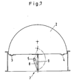
- FIG. 5 shows a pivoting flap arrangement 1 for round cross sections, in which two semicircular flaps 2 are each pivotably arranged via a rotary flap shaft 22.
- the rotary valve shafts 22 are mounted centrally in the longitudinal direction in parallel in a circular cross section. Transversely offset by 90 °, the drive shaft 5 is arranged offset parallel to the central axis.
- a web 25 is mounted below the rotary valve shafts.
- a further bearing point 26 is attached to the web 25.
- the swivel mechanism for closing or opening the flaps takes place as in the manner described at the beginning.
- FIG. 8 A further embodiment of the shut-off device according to the invention is shown in FIG. 8.
- the flue gases coming from the direction of arrow 27 can be forwarded in the direction of arrow 28 to a heat exchanger or the flue gases can be diverted in the direction of arrow 29 by actuating the shut-off devices Stack.
- a drive shaft 5 and 51 are arranged in each channel branch 28, 29 for actuating the shut-off elements.
- a bevel gear 30 is arranged at the intersection of the mutually perpendicular shafts 5 and 51.
- a drive unit 31 is rotatably connected to the bevel gear 30. If the drive unit 31 is actuated, the flaps 2 in the flue gas duct close to the heat exchanger and at the same time the flaps 2 in the flue gas duct open to the chimney. This makes it easy to
Landscapes
- Engineering & Computer Science (AREA)
- General Engineering & Computer Science (AREA)
- Mechanical Engineering (AREA)
- Lift Valve (AREA)
- Air-Flow Control Members (AREA)
- Mechanically-Actuated Valves (AREA)
- Incineration Of Waste (AREA)
Abstract
Description
Die Erfindung betrifft eine Absperrvorrichtung für Kanäle mit grossen Querschnitten, insbesondere Rauchgaskanäle für Kraftwerksanlagen, welche mindestens eine entweder in den oder innerhalb der Kanalwände über mindestens eine Drehklappenwelle gelagert Klappe aufweist, die mittels mindestens einer Antriebswelle sowie mit aus Kurbelarmen und Spannarmen bestehenden Spannhebelanordnungen schwenkbar ist.The invention relates to a shut-off device for ducts with large cross sections, in particular flue gas ducts for power plants, which has at least one flap mounted either in or within the duct walls via at least one rotary valve shaft, which can be pivoted by means of at least one drive shaft and with clamping lever arrangements consisting of crank arms and clamping arms.
Derartige Absperrvorrichtungen sind in verschiedenen Ausführungsformen bekannt. Derartige Absperrvorrichtungen weisen dabei mindestens zwei Klappen auf, wenn sie bei Kraftwerken und dort insbesondere im Abgas- oder Rauchgasbereich verwendet werden, ausserordentlich grosse Querschnitte von 100 m² und mehr auf, wodruch erhebliche Probleme beim Bewegen dieser grossen Klappenflügel und bei ihrem Anpressen gegen die im Kanal liegenden Dichtungen auftreten. Deshalb ist es erforderlich, mindestens zwei Klappen zur Abschottung des Rauchgasstromes in einem Kanalquerschnitt der Grösse einzubauen. Um die kinetische Energie der Rauchgase beim Schliessvorgang der Flügelklappen aufzufangen und zur Bewegung der grossen Massen der Flügelteile wird jedem Flügelteil eine Antriebswelle zugeordnet. Die jedem Flügelteil zugeordnete Antriebswelle ist dabei parallel zur Schwenkachse der Klappe drehbar gelagert. Dabei wird jeder Antriebswelle ein entweder innenliegender Antrieb oder aussen liegender Antrieb zugeordnet. Dadurch, dass jeder Klappe oder Flügelteil eine Antriebswelle zugeordnet ist, bedeutet das, dass im geöffneten Zustand der Absperrvorrichtung die im Kanalquerschnitt gelagerten Wellen einen Strömungswiderstand bilden. Weiterhin sind innenliegende Antriebsaggregate dem aggressiven Rauchgasenim Strömungskanal ausgesetzt. Diese Anordnung einer Absperrvorrichtung in derart grossen Querschnitten führt zu einem erheblichen baulichen Aufwand und dementsprechend hohen Kosten.Such shut-off devices are known in various embodiments. Such shut-off devices have at least two flaps when they are used in power plants and there in particular in the exhaust or flue gas area, extraordinarily large cross sections of 100 m² and more, which causes considerable problems when moving these large flap wings and when pressing them against those in the channel lying seals occur. It is therefore necessary to install at least two flaps to seal off the flue gas flow in a duct cross-section of the size. In order to absorb the kinetic energy of the flue gases during the closing process of the wing flaps and to move the large masses of the wing parts, a drive shaft is assigned to each wing part. The drive shaft assigned to each wing part is rotatably mounted parallel to the pivot axis of the flap. Each drive shaft is assigned either an internal drive or an external drive. The fact that each flap or wing part is assigned a drive shaft means this means that when the shut-off device is open, the shafts mounted in the channel cross section form a flow resistance. Furthermore, internal drive units are exposed to the aggressive flue gases in the flow channel. This arrangement of a shut-off device in such large cross sections leads to a considerable structural outlay and correspondingly high costs.
Der Erfindung liegt daher die Aufgabe zugrunde, für diesen Zweck eine Absperrvorrichtung so auszubilden, dass mit geringem Aufwand Klappen derartiger Grösse in einem Rauchgaskanal bewegt werden können, so dass sich insgesamt niedrige Bau- und Wartungskosten ergeben.The invention is therefore based on the object for this purpose to design a shut-off device such that flaps of such size can be moved in a flue gas duct with little effort, so that overall low construction and maintenance costs result.
Gegenstand der Erfindung ist daher eine Absperrvorrichtung für Kanaäle mit grossen Querschnitten, insbesondere Rauchgaskanäle für Kraftwe ken derart auszubilden, dass bei einer mindestens zwei Klappen aufweisenden Absperrvorrichtung die Antriebswelle quer zur Drehkl appenwelle angeordnet ist.The invention therefore relates to a shut-off device for channels with large cross-sections, in particular flue gas channels for Kraftwe ken, such that in a shut-off device having at least two flaps, the drive shaft is arranged transversely to the rotary valve shaft.
Durch eine Querverlagerung der Antriebswelle im Kanalquerschnitt ist es möglich geworden, über Spannhebelanordnungen welche Klappen und Antriebswelle verbinden, als Öffnungsorgan nur eine Welle im Querschnitt anzuordnen. Dadurch ist erreicht worden, dass zum einen der bauliche Aufwand derartiger Absperrvorrichtungen gesenkt werden kann und zum anderen die Strömungsverluste bei geöffnetem Zustand der Absperrvorrichtung verringert werden.A transverse displacement of the drive shaft in the channel cross-section has made it possible to arrange only one shaft in cross-section as an opening member by means of clamping lever arrangements which connect flaps and drive shaft. It has thereby been achieved that on the one hand the structural complexity of such shut-off devices can be reduced and on the other hand the flow losses when the shut-off device is open are reduced.
Vorzugsweise ist dabei die Antriebswelle vor der Klappenanordnung im Kanalquerschnitt drehbar gelagert. Dadurch, dass die Antriebswelle über ein ausserhalb des Kanalquerschnitts angebrachtes Antriebsaggregat antreibbar ist wird erreicht, dass entweder ein E-Antrieb oder Hydraulikantrieb vor den aggressiven Rauchgasen geschützt wird. Der Verschleiss und der Wartungsaufwand derartiger Aggregate kann dadurch erheblich gesenkt werden, was wiederum entsprechende Kostenvorteile mit sich bringt.The drive shaft is preferably rotatably mounted in the channel cross section in front of the flap arrangement. The fact that the drive shaft can be driven via a drive unit mounted outside the channel cross section it is achieved that either an electric drive or hydraulic drive is protected from the aggressive flue gases. The wear and the maintenance effort of such units can thereby be reduced considerably, which in turn brings corresponding cost advantages.
Nach einer Weiterbildung der Erfindung ist es zweckmässig, dass sich bei Klappen mit grosser Höhe parallel zueinanderliegende Antriebswellen im Kanalquerschnittsbereich befinden und die Antriebswellenenden über eine quer dazu liegende ausserhalb des Kanalquerschnitts über Getriebe verbindende Antriebswellen antreibbar sind. Bei Klappen mit grosser Höhe, welche einem derartigen Kanalquerschnitt angepasst sind, können aufgrund der Anordnung von nur einer Antriebswelle während des Schliess- und Öffnungsvorganges grosse Biegemomente durch die kinetische Energie der Rauchgase auftreten. Zur Ausschaltung derartiger Biegemomente bietet sich an, die Klappen zu versteifen was jedoch den Nachteil mit sich bringt, dass die Klappen ein hohes Eigengewicht bekommen. Zur Lösung bietet sich daher an, bei derartigen Klappenhöhen zwei parallel zueinanderliegende Antriebswellen im Kanalquerschnittsbereich anzuordnen und die durch die Kanalwände durchtretenden Wellenenden über eine quer dazu angeordnete Antriebswelle und verbindenden Getrieben anzutreiben. Dadurch, dass im oberen Bereich und im unteren Bereich der hohen Klappen eine Antriebswelle angeordnet ist, können somit die auftretenden Biegemomente beim Öffnungs- und Schliessvorgang der Sperrvorrichtung ausgeschaltet werden und eine Überdimensionierung der Klappenflügel ist nicht mehr erforderlich.According to a further development of the invention, it is expedient that, in the case of flaps with a large height, drive shafts lying parallel to one another are located in the channel cross-sectional area and the drive shaft ends can be driven via drive shafts which lie transversely to the outside of the channel cross-section via gears. In the case of flaps with a large height, which are adapted to such a channel cross section, large bending moments due to the kinetic energy of the flue gases can occur due to the arrangement of only one drive shaft during the closing and opening process. To eliminate such bending moments, it is advisable to stiffen the flaps, but this has the disadvantage that the flaps have a high weight. The solution to this problem is to arrange two drive shafts lying parallel to one another in the channel cross-sectional area at such valve heights and to drive the shaft ends passing through the channel walls via a drive shaft arranged transversely thereto and connecting gears. Due to the fact that a drive shaft is arranged in the upper area and in the lower area of the high flaps, the bending moments that occur during the opening and closing process of the locking device can thus be switched off and an oversizing of the flap wings is no longer necessary.
Vorzugsweise sind mehrere Spannhebelanordnungen, welche die Klappe oder Klappen mit der oder den Antriebswellen gelenkig verbinden auf der oder den im Kanalquerschnitt gelagerten Antriebswellen befestigt. Durch die Anbringung oder Befestigung mehrerer Spannhebelanordnungen auf der quer gelagerten Antriebswelle ist es möglich geworden, dass mehrere Klappenflügel im Kanalquerschnitt angesteuert werden können.A plurality of tensioning lever arrangements, which connect the flap or flaps with the drive shaft or shafts, are preferably fastened on the drive shaft or shafts mounted in the channel cross section. By attaching or fastening a plurality of tensioning lever arrangements on the transversely mounted drive shaft, it has become possible for several flap blades in the channel cross section to be controlled.
Nach einer Weiterbildung der Erfindung sind die Kurbelarme der Spannhebelanordnung drehfest mit der bzw. den Antriebswellen verbunden, wobei das freie Ende des Kurbelarmes senkrecht zur Ebene der geschlossenen Klappe steht und ein Spannarm die Klappe mit dem freien Ende des Kurbelarmes gelenkig verbindet. Dadurch, dass der oder die Kurbelarme senkrecht zur Ebene der geschlossenen Klappe stehen ist gewährleistet, dass die Kurbelarme nach einer Öffnungsschwenkbewegung um 180° in Strömungsrichtung des Rauchgases weisen. Dadurch ergeben sich keine zusätzlichen Strömungswiderstände im Kanalquerschnitt.According to a development of the invention, the crank arms of the tensioning lever arrangement are connected in a rotationally fixed manner to the drive shaft (s), the free end of the crank arm being perpendicular to the plane of the closed flap and a tensioning arm articulatedly connecting the flap to the free end of the crank arm. The fact that the crank arm or arms are perpendicular to the plane of the closed flap ensures that the crank arms point in the flow direction of the flue gas after an opening pivoting movement by 180 °. This means that there are no additional flow resistances in the channel cross-section.
Nach einer Weiterbildung der Erfindung besteht die Möglichkeit, die Drehklappenwellen zentrisch in der Längsachse anzuordnen, wobei die Spannarme der Spannhebelanordnung aussermittig zur Längsachse angreifen. Bei einer derartigen Bauausführung ist es vorteilhaft, einen Gelenkhebel mit der zentrisch gelagerten Längsachse einer Jalousieklappe drehfest zu verbinden und in einem Winkel zur Klappenebene anzuordnen, wobei das freie Ende des Gelenkhebels mit dem Spannarm gelenkig verbunden ist.According to a development of the invention, there is the possibility of arranging the rotary valve shafts centrally in the longitudinal axis, the tensioning arms of the tensioning lever arrangement acting eccentrically to the longitudinal axis. In a construction of this type, it is advantageous to connect an articulated lever in a rotationally fixed manner to the centrally mounted longitudinal axis of a louvre flap and to arrange it at an angle to the flap plane, the free end of the articulated lever being articulated to the tensioning arm.
Bei einer vorteilhaften Weiterbildung der Erfindung ist es zweckmässig, bei einem zueinander senkrecht liegenden Kanal abzweig in jedem Abzweig mindestens eine Antriebswelle anzuordnen und im Schnittpunkt der beiden Wellen ausserhalb des Kanalzweiges ein Getriebe, beispielsweise Kegelradgetriebe, die beiden Antriebswellen drehbar zu verbinden und beide Antriebswellen über ein Antriebsaggregat anzutreiben. Dadurch wird erreicht, dass die beiden Kanalzweige wechselseitig geöffnet und geschlossen werden können und somit die Gesamt anordnung der Kanalverzweigung die Wirkungsweise einer Weiche zur Umleitung von Rauchgasströmen in Kanälen mit grossen Querschnitten besitzt.In an advantageous development of the invention, it is expedient for a channel lying perpendicular to one another to arrange in each branch at least one drive shaft and at the intersection of the two shafts outside the channel branch a gear, for example bevel gear, to connect the two drive shafts rotatably and to drive both drive shafts via a drive unit. This ensures that the two duct branches can be opened and closed alternately and thus the overall arrangement of the duct branching has the effect of a switch for diverting flue gas flows in ducts with large cross sections.
Ein Ausführungsbeispiel gemäss der Erfindung ist im folgenden anhand der Zeichnung dargestellt. Darin zeigt
- Fig. 1 in schematischer und perspektivischer Darstellung die Antriebsseite einer mehrflügeligen Schwenkklappenanordnung mit einer zur Drehrichtung der Klappen querliegenden Antriebswelle und entsprechendem Klappengestänge,
- Fig. 2 eine Darstellung gemäss Fig. 1 mit zwei parallel zueinander liegenden Antriebswellen,
- Fig. 3 eine weitere Ausführungsform der Erfindung einer Teildraufsicht mit zentrisch gelagerten Jalousieklappen,
- Fig. 4 eine Weiterbildung der Darstellung gemäss Fig. 3,
- Fig. 5 eine zweiflügeige Absperrklappe für kreisförmige Querschnitte gemäss der Erfindung in der Draufsicht,
- Fig. 6 einen senkrechten Schnitt entsprechend der Linie VI-VI der Fig. 5,
- Fig. 7 einen senkrechten Schnitt der Linie VII-VII der Fig. 6,
- Fig. 8 eine Draufsicht einer Klappkombination gem. der Erfindung mit zwei zueinander rechtwinklig angeordneten Antriebswellen und einem Antrieb.
- 1 shows a schematic and perspective illustration of the drive side of a multi-wing swivel flap arrangement with a drive shaft which is transverse to the direction of rotation of the flaps and a corresponding flap linkage,
- 2 shows a representation according to FIG. 1 with two drive shafts lying parallel to one another,
- 3 shows a further embodiment of the invention of a partial top view with centrally mounted louvre flaps,
- 4 shows a development of the representation according to FIG. 3,
- 5 is a top view of a double-leaf butterfly valve for circular cross-sections according to the invention,
- 6 is a vertical section along the line VI-VI of FIG. 5,
- 7 is a vertical section on the line VII-VII of FIG. 6,
- Fig. 8 is a plan view of a folding combination acc. the invention with two mutually perpendicular drive shafts and a drive.
In der Zeichnung Fig. 1 ist eine mehrflügelige Schwenkklappenanordnung in ihrer Gesamtheit mit 1 bezeichnet. Die Schwenkklappenanordnung 1 wird insbesondere in Kanälen mit grossen Rechteckquerschnitten (beispielsweise in Rauchgaskanälen von Kraftwerken) zur Abschottung eines Rauchgasstromes verwendet. Die Einzelklappen der Schwenkklappenanordnung 1 sind mit 2 bezeichnet. Die Einzelklappen 2 sind über Scharniere 3 und 4 schwenkbar im Rauchgaskanal angeordnet. In der Zeichnung schematisch dargestellte Drehklappenwellen sind entweder ausserhalb oder aber innerhalb der Kanalwände gelagert bzw. befestigt. Dabei kann auf einer Drehklappenwelle eine links und eine rechtsöffnende Klappe 2 schwenkbar angeordnet sein. Eine weitere Ausführungsmöglichkeit ist, dass jeder Klappe 2 eine Drehklappenwelle zugeordnet ist. Eine Antriebswelle 5 ist quer zur Drehrichtung der Klappen 2 vor der Schwenkklappenanordnung 1 angeordnet. Die Antriebswelle 5 ist in Lagern 6 drehbar gelagert. Spannhebelanordnungen 7 verbinden die Einzelklappen 2 mit der Antriebswelle 5. Auf der Antriebswelle 5 sind Kurbelarme 8 drehfest angebracht. Die Kurbelarme 8 sind auf der Antriebswelle 5 so befestigt, dass sie mit ihrem freien Ende zur Ebene der Klappe 2 senkrecht stehen. Mit den freien Enden der Kurbelarme 8 sind Spannarme 9 gelenkig verbunden, wobei dessen anderes Ende über ein Gelenk an der zugehörigen Klappe 2 angreift.In the drawing Fig. 1, a multi-wing swivel flap arrangement is designated in its entirety by 1. The swing flap arrangement 1 is used in particular in ducts with large rectangular cross sections (for example in flue gas ducts of power plants) for the isolation of a flue gas flow. The individual flaps of the swivel flap arrangement 1 are designated 2. The
Wird über ein in der Zeichnung nicht dargestelltes Antriebsaggregat die Antriebswelle 5 gegen den Uhrzeigersinn um 180° gedreht, so schwenkt das freie Ende des Kurbelarmes 8 entsprechend der Raumkurve 11 auf die gegenüberliegende Seite. Während dieses Schwenkvorganges legt der Gelenkpunkt, an welchem der Spannarm 9 mit der Klappe 2 gelenkig verbunden ist einen Weg, entsprechend der Raumkurve 12 zurück.If the
Durch die Spannhebelanordnung 7 auf der Antriebswelle 5 werden nach einer Drehung der Antriebswelle 5 um 180° die Klappen 2 in Strömungsrichtung 14 geöffnet. Um wieder die Schließstellung der Klappen 2 zu erreichen, wird die Antriebswelle 5 im Sinne der Pfeilrichtung 10 mit dem Uhrzeigersinn gedreht. Während der Schliess- und Öffnungsbewegung der Klappen 2 legen die freien Eckpunkte der Klappen 2 einen Weg entsprechen der strichpunktierten Linie 13 zurück.The
Fig. 2 zeigt eine mehrflügelige Schwenkklappenanordnung, bei der die Klappen 2 eine verhältnismässig grosse Höhe aufweisen. Zur Ansteuerung dieser hohen Klappen 2 sind zwei Antriebswellen 5 und 15 parallel zueinander quer zur Drehrichtung der Klappen 2 angeordnet. Beide Antriebswellen 5 und 15 öffnen und schliessen wie bereits in Fig. 1 beschrieben über Spannhebelanordnungen 7 die Klappen 2. Getriebe 16 und 17 verbinden die Antriebswelle 5 und die Antriebswelle 15 mit einer quer dazu liegenden Antriebswelle 18. Wird über ein in der Zeichnung nicht dargestelltes Antriebsaggregat ein Moment im Sinne der Pfeilrichtung 19 auf die Antriebswelle 18 gebracht, so wird der Kraftschluss über die Getriebe 16 und 17 auf die Antriebswellen 5 und 15 weitergeleitet, so dass die Kurbelarme 8 im Sinne der Pfeilrichtung 20 und 21 verschwenkt werden.Fig. 2 shows a multi-wing swivel flap arrangement in which the
Bei dem Ausführungsbeispiel gemäss Fig. 3 sind Drehklappenwellen 22 mittig in der Längsache der Klappen 2 angebracht. Über die Spannhebelanordnung 7 ist die quer zur Drehrichtung liegende Antriebswelle 5 gelenkig mit den Klappen 2 verbunden. Hierbei ist die Anordnung der Spannhebelanordnung 7 so gewählt, dass der Spannarm 9 an einem Gelenkpunkt auf der Klappe 2 angreift, welcher ausser mittig liegt.In the exemplary embodiment according to FIG. 3,
Beim Ausführungsbeispiel gem. Fig. 4 ist ein Gelenkhebel 24 drehfest mit der Drehklappenwelle 22 verbunden. Am freien Ende des Gelenkhebels 24 greift in gleicher Weise wie in Fig. 3 der Spannarm 9 an.In the embodiment according to 4, an articulated
Die Fig. 5 zeigt eine Schwenkklappenanordnung 1 für runde Querschnitte, bei der zwei halbkreisförmige Klappen 2 jeweils über eine Drehklappenwelle 22 schwenkbar angeordnet sind. Die Drehklappenwellen 22 sind mittig in Längsrichtung parallel im Kreisquerschnitt gelagert. Quer dazu um 90° versetzt, ist die Antriebswelle 5 parallel zur Mittelachse versetzt angeordnet. In der Mittelachse ist ein Steg 25 unterhalb der Drehklappenwellen gelagert. An dem Steg 25 ist ein weiterer Lagerpunkt 26 angebracht. Der Schwenkmechanismus zum Schliessen oder zum Öffnen der Klappen vollzieht sich wie in der eingangs beschriebenen Art.5 shows a pivoting flap arrangement 1 for round cross sections, in which two
Eine weitere Ausführungsform des Absperrorganes gemäss der Erfindung zeigt Fig. 8. Hier können die aus der Richtung des Pfeils 27 kommenden Rauchgase in Richtung des Pfeiles 28 zu einem Wärmetauscher weitergeleitet werden oder aber durch Betätigen der Absperrorgane die Rauchgase umgeleitet werden in Richtung des Pfeiles 29 zum Kamin. Zur Betätigung der Absperrorgane sind in jedem Kanalzweig 28,29 jeweils eine Antriebswelle 5 und 51 angeordnet. Im Schnittpunkt der zueinander senkrecht stehenden Wellen 5 und 51 ist ein Kegelradgetriebe 30 angeordnet. Mit dem Kegelradgetriebe 30 ist ein Antriebsaggregat 31 drehbar verbunden. Wird das Antriebsaggregat 31 betätigt, so schliessen die Klappen 2 im Rauchgaskanal zum Wärmetauscher und gleichzeitig werden die Klappen 2 im Rauchgaskanal zum Kamin geöffnet. Dadurch lässt sich auf einfache Weise eineA further embodiment of the shut-off device according to the invention is shown in FIG. 8. Here, the flue gases coming from the direction of
Rauchgasumlenkung mit zwei Antriebswellen 5 und 51 und einem Antriebsaggregat 31 erzielen, wobei die beiden Kanalzweige sechselseitig geöffnet und geschlossen werden können. Die Gesamtanordnung der Kanalverzweigung hat somit die Wirkungsweise einer Weiche zur Umleitung von Rauchgasströmen in Kanälen mit grossen Querschnitten.Achieve flue gas deflection with two
Claims (9)
Applications Claiming Priority (2)
| Application Number | Priority Date | Filing Date | Title |
|---|---|---|---|
| DE3836861A DE3836861A1 (en) | 1988-10-27 | 1988-10-27 | SHUT-OFF DEVICE FOR CHANNELS WITH LARGE CROSS-SECTIONS, IN PARTICULAR SMOKE GAS CHANNELS |
| DE3836861 | 1988-10-27 |
Publications (1)
| Publication Number | Publication Date |
|---|---|
| EP0365746A1 true EP0365746A1 (en) | 1990-05-02 |
Family
ID=6366140
Family Applications (1)
| Application Number | Title | Priority Date | Filing Date |
|---|---|---|---|
| EP89111818A Ceased EP0365746A1 (en) | 1988-10-27 | 1989-06-29 | Shut-off device for conduits having a large cross-section, especially flue gas conduits |
Country Status (5)
| Country | Link |
|---|---|
| US (1) | US5007456A (en) |
| EP (1) | EP0365746A1 (en) |
| DE (1) | DE3836861A1 (en) |
| DK (1) | DK532489A (en) |
| FI (1) | FI894401A (en) |
Cited By (5)
| Publication number | Priority date | Publication date | Assignee | Title |
|---|---|---|---|---|
| AU710388B2 (en) * | 1996-04-10 | 1999-09-16 | Murray Joseph Hall | Improvements to damper (chimney) |
| DE102006059029A1 (en) * | 2006-12-14 | 2008-06-26 | Audi Ag | Rotary valve for regulating flow, especially of liquids, e.g. in motor vehicle cooling systems comprises cross-section-adjusting elements that are each connected to a common drive shaft via a rotating gear |
| DE102008030004A1 (en) * | 2008-06-24 | 2009-12-31 | Mahle International Gmbh | actuator |
| DE102008030006A1 (en) * | 2008-06-24 | 2009-12-31 | Mahle International Gmbh | actuator |
| DE102008030005A1 (en) * | 2008-06-24 | 2009-12-31 | Mahle International Gmbh | actuator |
Families Citing this family (7)
| Publication number | Priority date | Publication date | Assignee | Title |
|---|---|---|---|---|
| DE19541591B4 (en) * | 1995-11-08 | 2010-03-18 | Camfil Farr Power Systems Gmbh | Wing flap arrangement for lines of large nominal widths |
| DE19648813C2 (en) * | 1996-11-26 | 2000-02-24 | Daimler Chrysler Ag | Air conditioning system for a motor vehicle |
| DE19729648A1 (en) * | 1997-07-11 | 1999-01-14 | Mann & Hummel Filter | Device for adjusting a valve flap |
| DE19947056A1 (en) * | 1999-09-30 | 2001-04-05 | Janich Gmbh & Co | Smoke flue regulating and shutoff valve is coupled to drive shaft by flush-joinable plates allowing blade removal and framework collapse for manageable transport. |
| DE10019686A1 (en) * | 2000-04-20 | 2001-10-31 | Nem Power Systems Niederlassun | Flap, especially switch flap for large duct cross sections |
| CN101187474B (en) * | 2007-09-11 | 2010-06-23 | 中国神华能源股份有限公司 | Adjustable quick folding flue baffle door |
| CN105570915A (en) * | 2016-02-23 | 2016-05-11 | 上海必立建筑工程有限公司 | Pressure-inductive self-adjusting type baffle door |
Citations (6)
| Publication number | Priority date | Publication date | Assignee | Title |
|---|---|---|---|---|
| CH358655A (en) * | 1958-12-03 | 1961-11-30 | Emile Henrion Marie Charles | Butterfly valve |
| DE1550396B1 (en) * | 1966-06-15 | 1970-04-23 | Alfred Konrad Maschf | Actuating gear for flap valves |
| CH597569A5 (en) * | 1974-01-29 | 1978-04-14 | Colt Int Ltd | |
| US4114465A (en) * | 1976-12-06 | 1978-09-19 | Vapor Corporation | Modulating failsafe valve actuator using differential gearing |
| DE2535625B2 (en) * | 1975-08-09 | 1979-04-26 | Waermekraft-Gesellschaft Stober U. Morlock, 4350 Recklinghausen | Flap valve |
| US4300749A (en) * | 1979-12-13 | 1981-11-17 | Allis-Chalmers Corporation | Throttle valve |
Family Cites Families (7)
| Publication number | Priority date | Publication date | Assignee | Title |
|---|---|---|---|---|
| US1159566A (en) * | 1912-03-04 | 1915-11-09 | Leo A Brigel | Controlling mechanism for automobile-heaters. |
| GB1293793A (en) * | 1969-04-28 | 1972-10-25 | Chrysler United Kingdom Ltd Fo | Improvements in or relating to valves |
| US4259987A (en) * | 1979-12-27 | 1981-04-07 | Honeywell Inc. | Linear damper system |
| US4442862A (en) * | 1980-05-30 | 1984-04-17 | Mccabe Francis J | Link bar operator for rotating blade dampers |
| US4457336A (en) * | 1982-07-14 | 1984-07-03 | Flanders Filters, Inc. | Air flow control apparatus |
| US4535811A (en) * | 1984-01-20 | 1985-08-20 | Flanders Filters, Inc. | Air flow control apparatus |
| US4749004A (en) * | 1987-05-06 | 1988-06-07 | The Boeing Company | Airflow control valve having single inlet and multiple outlets |
-
1988
- 1988-10-27 DE DE3836861A patent/DE3836861A1/en not_active Ceased
-
1989
- 1989-06-29 EP EP89111818A patent/EP0365746A1/en not_active Ceased
- 1989-09-18 FI FI894401A patent/FI894401A/en not_active Application Discontinuation
- 1989-10-20 US US07/424,596 patent/US5007456A/en not_active Expired - Fee Related
- 1989-10-26 DK DK532489A patent/DK532489A/en not_active Application Discontinuation
Patent Citations (6)
| Publication number | Priority date | Publication date | Assignee | Title |
|---|---|---|---|---|
| CH358655A (en) * | 1958-12-03 | 1961-11-30 | Emile Henrion Marie Charles | Butterfly valve |
| DE1550396B1 (en) * | 1966-06-15 | 1970-04-23 | Alfred Konrad Maschf | Actuating gear for flap valves |
| CH597569A5 (en) * | 1974-01-29 | 1978-04-14 | Colt Int Ltd | |
| DE2535625B2 (en) * | 1975-08-09 | 1979-04-26 | Waermekraft-Gesellschaft Stober U. Morlock, 4350 Recklinghausen | Flap valve |
| US4114465A (en) * | 1976-12-06 | 1978-09-19 | Vapor Corporation | Modulating failsafe valve actuator using differential gearing |
| US4300749A (en) * | 1979-12-13 | 1981-11-17 | Allis-Chalmers Corporation | Throttle valve |
Cited By (6)
| Publication number | Priority date | Publication date | Assignee | Title |
|---|---|---|---|---|
| AU710388B2 (en) * | 1996-04-10 | 1999-09-16 | Murray Joseph Hall | Improvements to damper (chimney) |
| DE102006059029A1 (en) * | 2006-12-14 | 2008-06-26 | Audi Ag | Rotary valve for regulating flow, especially of liquids, e.g. in motor vehicle cooling systems comprises cross-section-adjusting elements that are each connected to a common drive shaft via a rotating gear |
| DE102006059029B4 (en) * | 2006-12-14 | 2011-05-05 | Audi Ag | rotary vane |
| DE102008030004A1 (en) * | 2008-06-24 | 2009-12-31 | Mahle International Gmbh | actuator |
| DE102008030006A1 (en) * | 2008-06-24 | 2009-12-31 | Mahle International Gmbh | actuator |
| DE102008030005A1 (en) * | 2008-06-24 | 2009-12-31 | Mahle International Gmbh | actuator |
Also Published As
| Publication number | Publication date |
|---|---|
| DK532489D0 (en) | 1989-10-26 |
| FI894401A0 (en) | 1989-09-18 |
| US5007456A (en) | 1991-04-16 |
| DK532489A (en) | 1990-04-28 |
| FI894401A (en) | 1990-04-28 |
| DE3836861A1 (en) | 1990-05-03 |
Similar Documents
| Publication | Publication Date | Title |
|---|---|---|
| EP0365746A1 (en) | Shut-off device for conduits having a large cross-section, especially flue gas conduits | |
| CH643912A5 (en) | FIRE PROTECTION VALVE. | |
| EP1148297B1 (en) | Valve, in particular change-over valve for large cross section pipes | |
| EP1138861B1 (en) | Sliding and swinging door | |
| DE3440499C2 (en) | Device for harnessing hydromechanical energy | |
| DE4136907C2 (en) | ||
| EP3643849B1 (en) | Flap for roof, ceiling or façade | |
| DE2842906A1 (en) | FLOW CONTROL VALVE | |
| DE4033663C1 (en) | ||
| DE2507967A1 (en) | Folding leaf door with power-driven thrust element - performs simultaneous rotation and translates flow of force from drive to door leaf | |
| EP2251603B1 (en) | Blocking system for large sections of piping with a swinging flap | |
| DE102005046578B3 (en) | Light band arrangement for building, has two wings that are arranged adjacent to each other and are supported such that wings are raised and/or lowered in same direction during operation of opening and closing mechanisms | |
| DE3521636C2 (en) | ||
| EP0111576A1 (en) | Cut-off valve for hot gas, in particular flue gas | |
| DE2711138C3 (en) | Weather door | |
| EP0601493B1 (en) | Blower depending control device in a suction hose | |
| DE2600735A1 (en) | PIPE WITH A FLAP FOR LOCKING IT OFF | |
| DE2244972C2 (en) | Flap linkage for rotary flaps | |
| DE627811C (en) | Device for shutting off the flue gas ducts of combustion systems | |
| DE1070526B (en) | ||
| DE2633608A1 (en) | Multi-blade isolating damper for ventilation ducts - has each blade turned by linkage mechanism from operator | |
| DE2603242C3 (en) | Folding louvre for closing a delivery line for hot gases | |
| DE3637734A1 (en) | Device for shutting off large hot-gas pipelines | |
| AT397536B (en) | Arrangement for driving wing doors | |
| DE2522571C3 (en) | Drive device for a swing door |
Legal Events
| Date | Code | Title | Description |
|---|---|---|---|
| PUAI | Public reference made under article 153(3) epc to a published international application that has entered the european phase |
Free format text: ORIGINAL CODE: 0009012 |
|
| AK | Designated contracting states |
Kind code of ref document: A1 Designated state(s): AT BE CH DE FR GB IT LI LU NL SE |
|
| 17P | Request for examination filed |
Effective date: 19900602 |
|
| 17Q | First examination report despatched |
Effective date: 19901002 |
|
| STAA | Information on the status of an ep patent application or granted ep patent |
Free format text: STATUS: THE APPLICATION HAS BEEN REFUSED |
|
| 18R | Application refused |
Effective date: 19930220 |